
Tek plaka bağlantısı, veya kesme sekmesi, Bölümde belirtilen basit kesme bağlantılarından biridir. 10 AISC Kılavuzunun, ve imalatçıların favorisi çünkü grubun en ucuzu: bir tabak, bir kaynak hattı, bir cıvata grubu.
Plaka her zaman desteğe atölye kaynaklıdır ve genellikle cıvatalı bağlantı kirişine. Atölyede monte edilen bir çerçeve yerine kirişe kaynak yapılabilir. Yapmamanız gereken şey o kaynağı sahaya koymaktır.: Saha kaynağı, cıvata takmanın yanında yoğun emek gerektirir ve pahalıdır.
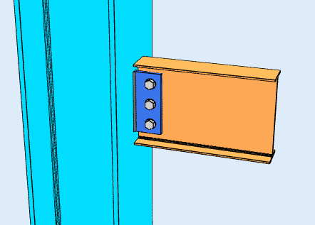
İki yapılandırma türü
Hangi konfigürasyonda olduğunuz, hangi kuralların geçerli olacağına karar verir, ve seçtiğiniz bir ayardan ziyade geometriden kaynaklanır.
-
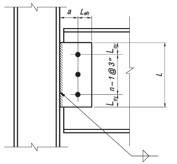
Geleneksel konfigürasyon
- Yalnızca tek bir dikey cıvata sırasına izin verilir. Bağlantıdaki cıvata sayısı arasında olmalıdır. 2 ve 12.
- Cıvata hattından kaynak hattına olan mesafe şuna eşit veya daha az olmalıdır: 3-1/2 içinde.
- standart delikler (STD) veya yatay kısa oluklu delikler (HSSL) Tabloda belirtildiği gibi kullanılmasına izin verilir 10-9 15. Baskı AISC kılavuzunun.
- Dikey kenar mesafesi, AISC Spesifikasyon Tablosu J3.4 gerekliliklerini karşılamalıdır. Yatay kenar mesafesi, hem plaka hem de kiriş ağı için 2d'den büyük veya eşit olmalıdır, d cıvata çapıdır.
- Levha kalınlığı veya kiriş gövde kalınlığı, Tabloda verilen maksimum kalınlık gereksinimini karşılamalıdır. 10-9 15. Baskı AISC kılavuzunun.

-
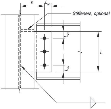
Genişletilmiş Yapılandırma
- Cıvata sayısı sınırlı değildir.
- Kaynak hattından desteğe en yakın cıvata hattına olan mesafe sınırlı değildir.
- Deliklerin kullanımı, AISC Spesifikasyonu Bölüm J3.2 gerekliliklerini karşılamalıdır..
- Yatay ve dikey kenar mesafeleri, AISC Spesifikasyon Tablosu J3.4 gerekliliklerini karşılamalıdır..

SkyCiv'de Tek Plakalı Bağlantı Tasarlama
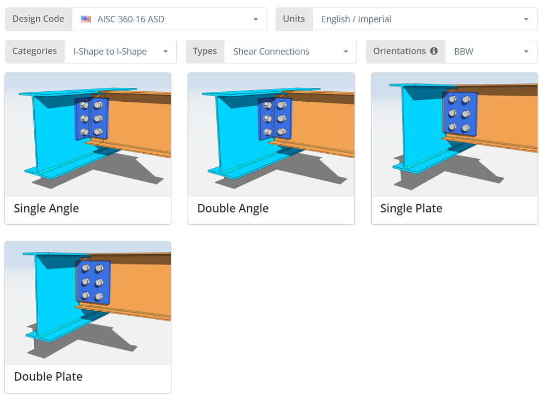
Tasarım kodu AISC olabilir 360-16 ASD veya LRFD, ve birimleri İngilizce/İngiliz veya SI/Metrik. Oryantasyon BCF'dir, BCW veya BBW; Her birinin ne anlama geldiğini öğrenmek için ipucunun üzerine gelin. Tıkla “Tek Plaka” fayans.
Ayrıntılar sekmesi
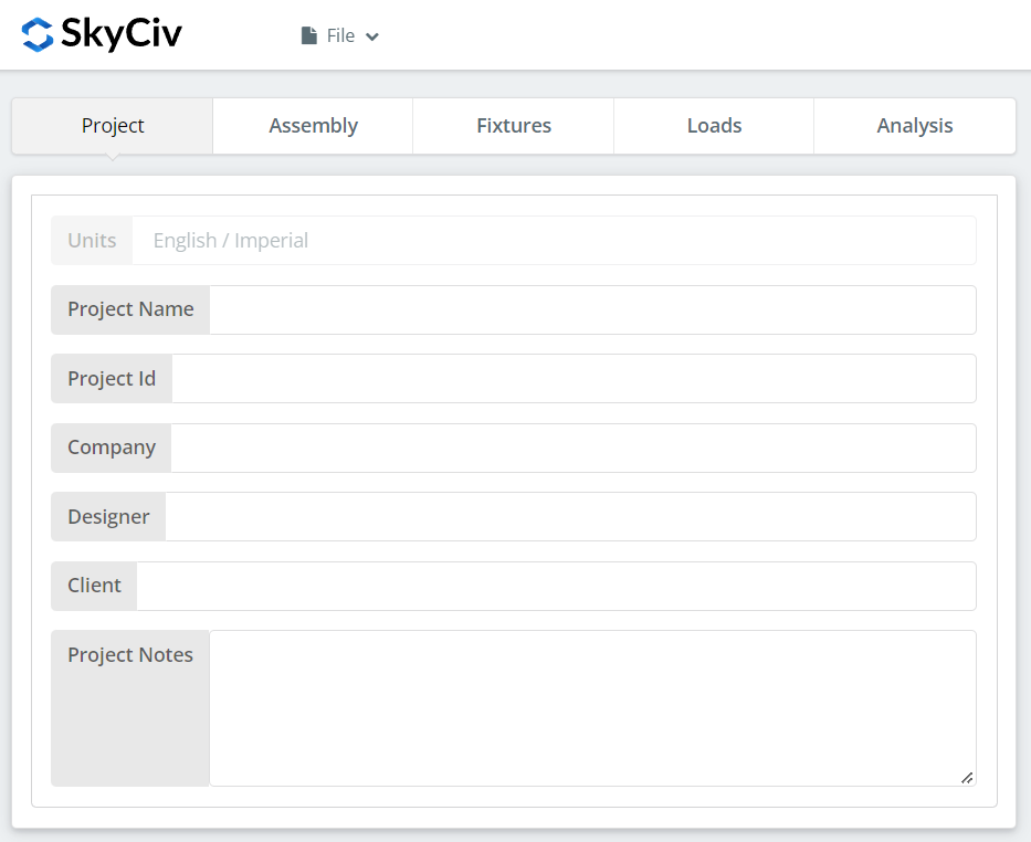
Proje ayrıntılarını buraya kaydedin. Hiçbiri hesaplamaları değiştirmiyor, ama rapora da yansıyor.
Montaj Sekmesi
Montaj'ın altında üç sekme bulunur: Kiriş, ışın, ve Bağlantı, tek plakayı tutan.
Kiriş Sekmesi
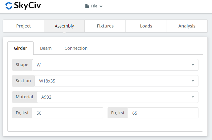
Destek elemanının kesitini ve malzeme derecesini belirtin. A992 ve A36 listede; başka bir şey için Özel'i seçin ve Fy ve Fu'ya girin.
Kiriş Sekmesi
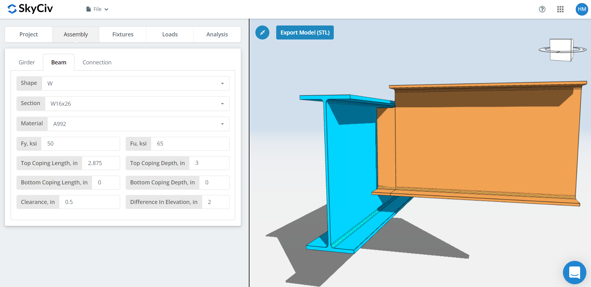
Işın için aynı girişler, artı başa çıkma boyutları, ışın açıklığı ve yükseklik farkı.
BBW yönelimi için başa çıkma otomatik olarak yapılır, ve bunu geçersiz kılabilirsiniz. Otomatik başlık, kiriş bölümünü değiştirdiğinizde yeniden hesaplama yapar, kiriş bölümü, açıklık veya yükseklik farkı.
Açıklık aynı zamanda sizi bir konfigürasyona ya da diğerine sokan şeydir. Kirişin hala kirişin içinde duracağı kadar küçük bir açıklık genellikle geleneksel tek bir plaka verecektir., kiriş flanşı, cıvatadan kiriş gövdesine olan mesafenin 3-1/2'yi aşacak kadar geniş olmadığı sürece″. Kirişi tamamen kiriş flanşının dışına koyan açıklık, uzatılmış tek bir plaka sağlar. Yükseklik farkı için, pozitif bir değer, kirişin kirişin üzerinde olduğu ve negatif bir değerin altında olduğu anlamına gelir.
Bağlantı Sekmesi
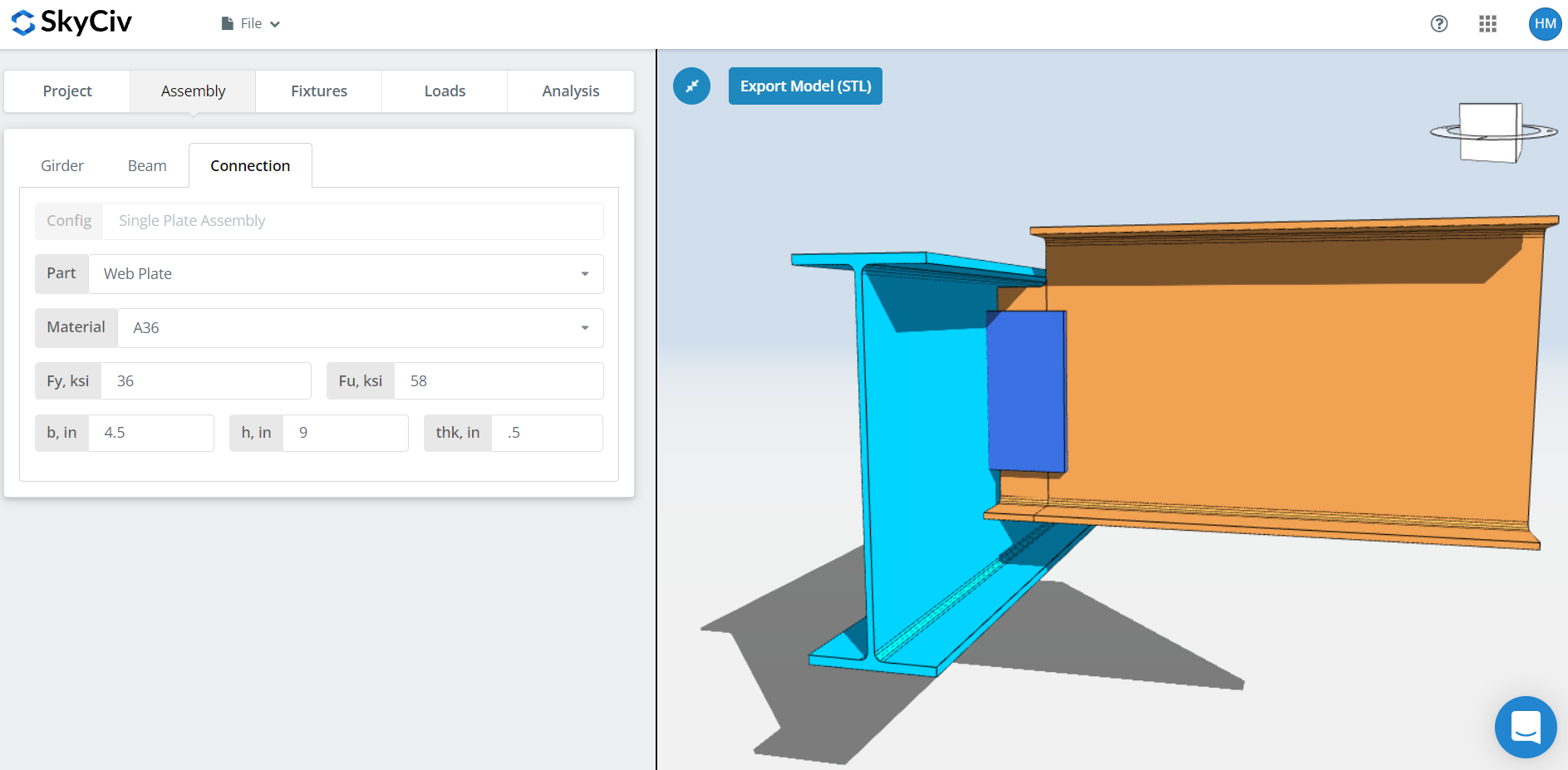
Plaka özelliklerini ayarlama: A36 veya A992 sınıfı, veya kendi Fy ve Fu'nuzla Özel, daha sonra plaka genişliği 'b', yükseklik 'h’ ve kalınlık 'teşekkür ederim'.
Hareket halindeyken 3D oluşturucuyu izleyin. Plaka yüksekliği kiriş derinliği dahilinde oturmalıdır, ve plaka genişliği, kirişin cıvatalanması veya kaynaklanması için yeterince geniş olmalıdır., genişletilmiş bir konfigürasyonda en önemli olan.
Fikstür 1 Sekme
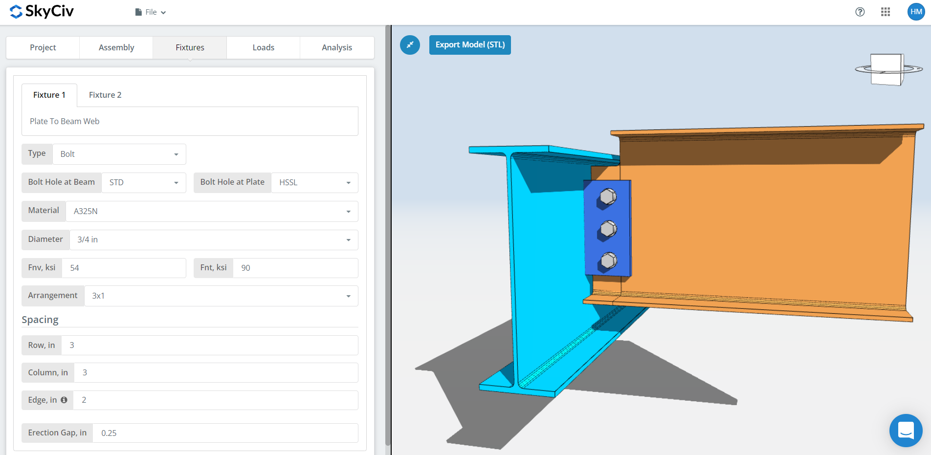
Fikstür 1 plakadan kirişe web bağlantısı nedir. Cıvatalı veya kaynaklı olabilir; bu izlenecek yol cıvatalı kullanımları kullanıyor.
İlk, kirişteki ve plakadaki cıvata deliği türleri. İmalatçılar genellikle standart delikler ister (STD) kirişte ve yatay kısa oluklu deliklerde (HSSL) tabakta, sahada montaj toleransını satın alan. Bu ikisinin aynı zamanda geleneksel konfigürasyonun izin verdiği tek delik tipi olduğuna dikkat edin., böylece büyük boyutlu deliklere ulaşmak sizi genişletilmiş yapılandırma kurallarına yönlendirir.
Sonraki, cıvata malzemesi veya kalitesi: A307, A325, A490 veya Özel. A325 ve A490, ASTM F3125 kapsamındaki kalitelerdir, eski bağımsız spesifikasyonları birleştiren. Rulman tipi bağlantı için N veya X'i ve kayma açısından kritik bağlantı için SC'yi seçin.
Kayma açısından kritik bağlantı noktaları, rulman tipine göre daha düşük tasarım cıvata kapasitesine sahiptir, bu yüzden onları kaymanın gerçekten önemli olduğu yerlerde kullanın: büyük boyutlu veya yarıklı delikler, yükün tersine çevrilmesi, veya yorgunluk. N ve X arasında, X, daha büyük cıvata kesme kapasitesini verir, ancak dişlerin kesme düzleminin dışında tutulması gerekir, ve montajcının bunu bilmesi gerekiyor. SC arası(Bir) ve SC(B), SC(B) daha büyük kapasite sağlar ve daha ayrıntılı bir şekilde hazırlanmış bir solma yüzeyi gerektirir, örneğin SSPC-SP6 ticari kumlama temizliği.
Daha sonra cıvata çapı, 5/8'den itibaren″ 1-1/2'ye″ veya metrik eşdeğerleri, ve düzenleme, kadar 12 cıvata satırları ve sütunları, satır ve sütun aralıklarıyla.
Bilmeye değer: daha fazla cıvata grubu kapasitesine ihtiyacınız varsa, Cıvata eklemek yerine boşluğu açmak bunu yapabilir, plaka yüksekliği hala kiriş derinliğine uyduğu sürece. Cıvata grubu gücü şunları kullanır: anlık dönme merkezi yöntemi (ICOR), dolayısıyla daha geniş bir aralık, gerçekte sağladığı kapasiteyle ilişkilendirilir. Önce imalatçınıza danışın, Yine de. Çoğu 3'ü tercih ediyor″ boyunca tipik aralık.
NS “kenar” girdi, kiriş ucundan ilk cıvata sütununa kadar olan mesafedir.
Son, ereksiyon boşluğu. Bu, kirişin sahadaki yerine bırakılmasını sağlayan boşluktur. Kapasite maliyeti, bu nedenle bunu yalnızca ereksiyonun gerçekten ihtiyaç duyduğu yerde belirtin.
Fikstür 2 Sekme
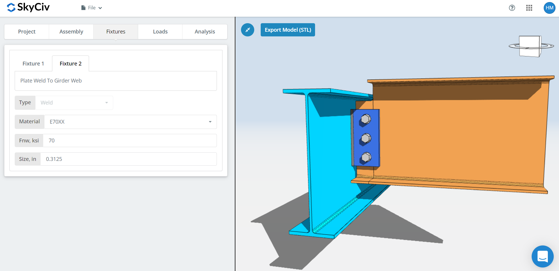
Fikstür 2 bağlantıyı destekleyen plakadır, bu desteğin kiriş ağı olup olmadığı, bir sütun flanşı veya bir sütun ağı. Tek bir plaka için bu yalnızca kaynaklanır.
Kaynak malzemesini belirtin, veya 'Özel’ elektrot listelenmemişse kendi Fnw'niz ile, daha sonra kaynak boyutu. Tek plakalı bağlantılar için kaynağın en az 5/8 çarpı levha kalınlığı, böylece kaynak plakayı geliştirir.
Bu kuralın planlamaya değer bir maliyet sonucu var. Tablo 8-12 15. Baskı AISC Kılavuzunun, sayfa 8-126, 5/16 arasında kaynak geçişlerinde büyük bir sıçrama gösterir″ ve 3/8″ fileto: 5/16″ tek geçişe ihtiyacı var, 3/8″ üçe ihtiyacı var. bir 1/2″ plakanın sadece 5/16'ya ihtiyacı var″ geliştirmek için fileto, bu da sizi tek geçiş bölgesinde tutar. Bağlantının kapasitesi yetersizse, kalınlığı artırmadan önce plaka yüksekliğini izin verilen maksimum değere yükseltin. Daha kalın bir plaka daha büyük bir kaynak gerektirir, ve daha büyük bir kaynak daha fazla geçiş anlamına gelir, daha fazla metal ve daha fazla işçilik süresi.
Yükler Sekmesi
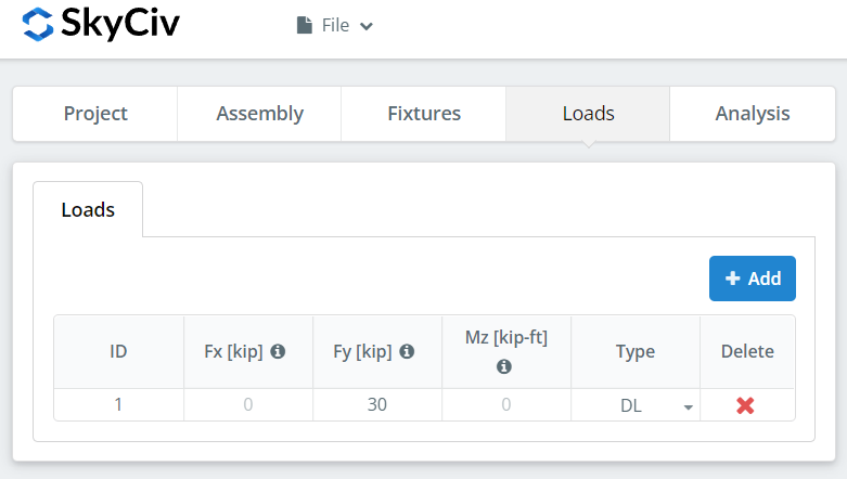
'Fy' altında dikey kesmeyi girin.
Yükü başlangıçta seçtiğiniz tasarım yöntemiyle eşleştirin. LRFD, tasarım gücüne karşı faktörlü yükleri alır; ASD, servis yüklerini izin verilen güce karşı alır. Yazılım hangisini yazdığınızı anlayamıyor.
Sonuçlar Sekmesi
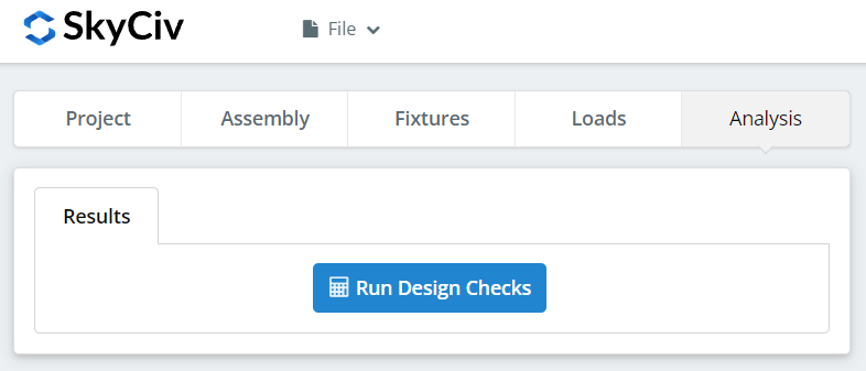
Tıklayın “Tasarım Kontrollerini Çalıştırın”. Önceki sekmelerde eksik olan her şey, sessizce varsayılan olarak ayarlanmak yerine burada işaretlenir.
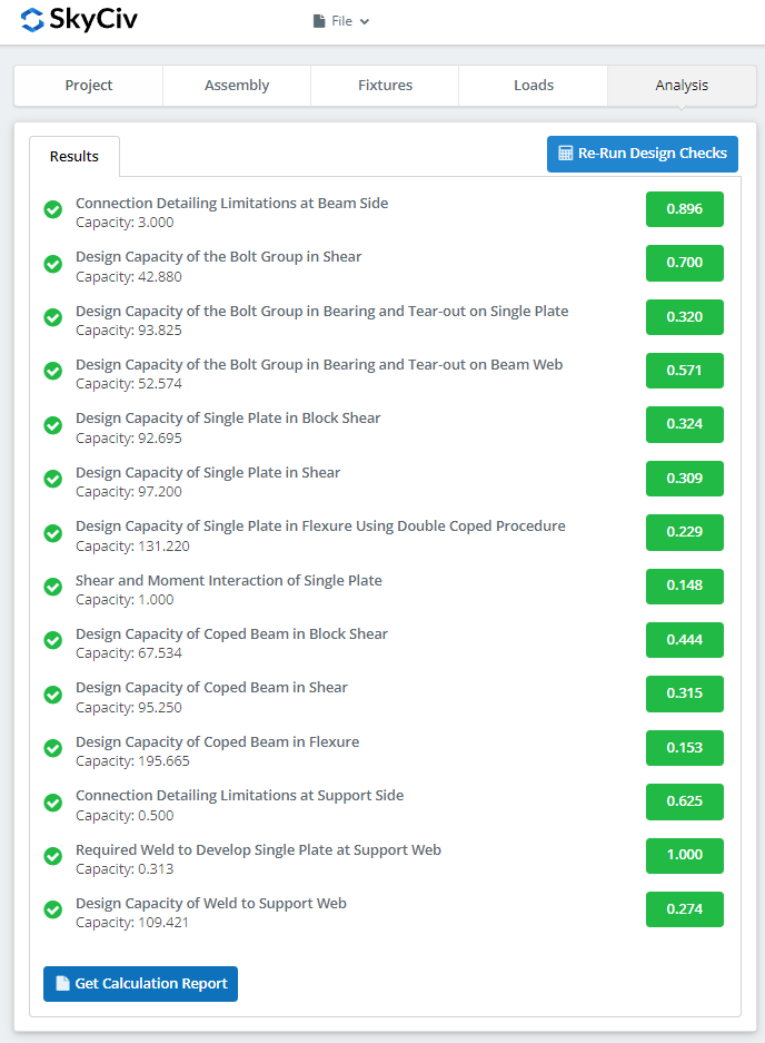
Özet, bağlantının geçip geçmediğini gösterir, her çeke karşı bir kullanım oranıyla. başarısız olursa, önceki sekmelerdeki girişleri değiştirin ve “Tasarım Kontrollerini Yeniden Çalıştırın”. Geçtiğinde, “Hesaplama Raporunu Görüntüle” ayrıntılı raporu açar.
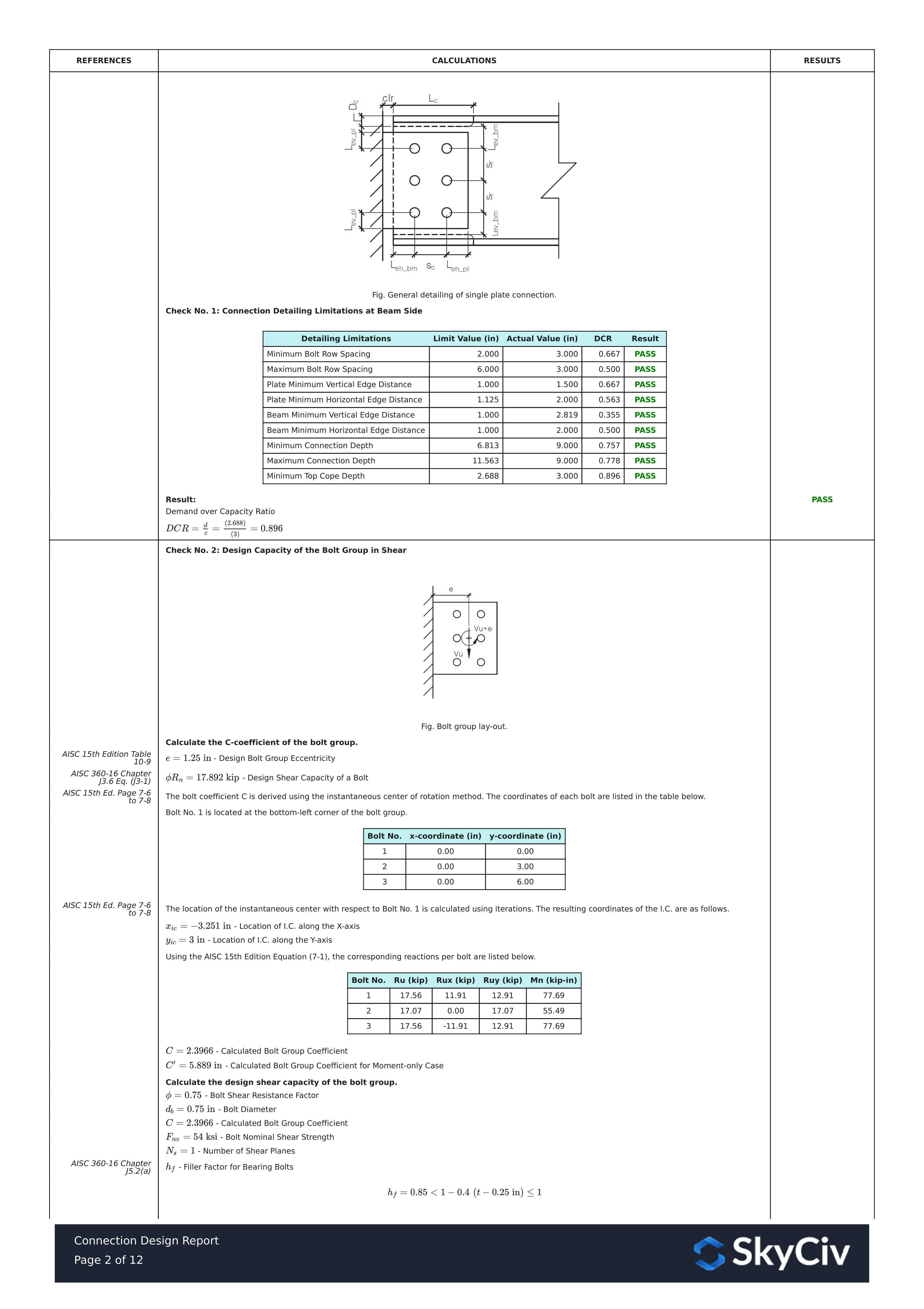
Bu rapordan bir alıntı. Her kontrol AISC kılavuzuna veya spesifikasyonuna referansını taşır, ve çalışma, spesifikasyonun kullandığı sırayı takip eder, böylece inceleme mühendisi bir sayıyı tersine mühendislik yapmak yerine satır satır okuyabilir.
İşte tam ayrıntılı hesaplama raporunun bir PDF kopyası: Bağlantı Tasarım Raporu.
Kendiniz Deneyin
Tek plakayı seçin, bölümlerinize girin, plaka ve kesme, ve her kontrolü kod referansıyla birlikte görün. Tarayıcıda çalışır, kurulacak hiçbir şey olmadan.
Ayrıca bkz. tek plaka bağlantı hesaplayıcısı, NS çift açılı hesaplayıcı, ve kesme bağlantıları genel bakış.
