Пример дизайна базовой пластины с использованием AISC 360-22 и ACI 318-19
Запись о проблеме
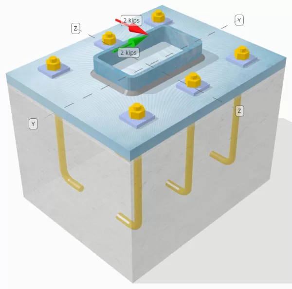
Определите, достаточно ли разработанного соединения с столбцами-базой для Vy=2-kip и VZ = 2 курица поперечные нагрузки.
Данные данных
Столбец:
Раздел столбца: HSS7X4X5/16
Область столбца: 7.59 в2
Материал столбца: A36
Опорная плита:
Размеры опорной плиты: 12 в х 14 в
Толщина опорной плиты: 3/4 в
Материал опорной плиты: A36
Раствор:
Толщина затирки: 0.25 в
бетон:
Бетонные размеры: 12 в х 14 в
Бетонная толщина: 10 в
Бетонный материал: 3000 фунтов на квадратный дюйм
Потрескался или не снят: Потрескался
Якоря:
Диаметр якоря: 1/2 в
Эффективная длина встраивания: 8 в
Толщина стиральной машины: 0.25 в
Связь с табличкой: Приваренная на базовую плиту
Швы:
Размер сварного шва: 1/4 в
Классификация металла наполнителя: Е70ХХ
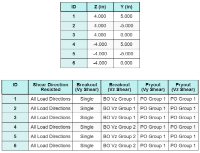
Якоря данных (из Skyciv Calculator):
Модель в бесплатном инструменте SkyCiv
Смоделируйте конструкцию опорной плиты, указанную выше, с помощью нашего бесплатного онлайн-инструмента сегодня.! Регистрация не требуется.
Определения
Путь нагрузки:
Дизайн следует по рекомендациям Руководство по проектированию AISC 1, 3Rd Edition, и ACI 318-19. Нагрузки на сдвиг, приложенные к колонне, а затем к опорному бетону через Якоря. Торы и сдвиговые выкупы не рассматриваются в этом примере, Поскольку эти механизмы не поддерживаются в текущем программном обеспечении.
По умолчанию, применяется сдвиговая нагрузка распределяется на все анкеры, либо с помощью сварных пластинчатых шайб, либо с помощью других инженерных средств.. Нагрузка, которую несет каждый якорь, определяется с помощью трех (3) случаи, указанные в Аси 318-19 Пункт 17.7.2 и рис. R17.7.2.1b. Затем каждый анкер передает нагрузку на опорный бетон внизу.. Распределение нагрузки в соответствии с этими ссылками также используется при проверке прочности на сдвиг анкерной стали, чтобы обеспечить непрерывность в предположениях о передаче нагрузки..
Как альтернатива, Программное обеспечение допускает упрощенное и более консервативное предположение, где вся нагрузка на сдвиг назначается только Якоря ближе к загруженному краю. В таком случае, Проверка емкости сдвига выполняется только на этих краях.
Якорные группы:
В Программное обеспечение SkyCiv для проектирования опорной плиты Включает интуитивно понятную особенность, которая определяет, какие якоря являются частью якоря для оценки Бетонное сдвиг прорыв и Бетонный сдвиг Прайут неудачи.
An Якорная группа определяется как два или более якоря с перекрывающимися областями сопротивления. В таком случае, Якоря действуют вместе, и их комбинированное сопротивление проверяется на приложенной нагрузке на группу.
А Одиночный якорь определяется как якорь, чья проектная область сопротивления не перекрывается с каким -либо другим. В таком случае, Якорь действует в одиночку, и приложенная сила сдвига на этом якоре проверяется непосредственно на его индивидуальное сопротивление.
Это различие позволяет программному обеспечению захватывать как поведение группы, так и индивидуальные характеристики привязки при оценке режимов отказа, связанных с сдвигом.
Пошаговые расчеты
Проверьте #1: Рассчитайте емкость сварки
Первым шагом является рассчитание Общая длина сварного шва Доступно, чтобы противостоять сдвигу. Поскольку опорная плита приварена вдоль периметра секции колонны, Общая длина сварного шва получается путем суммирования сварных швов со всех сторон.
\( L_{сварка} знак равно 2 \осталось( б_{полковник} – 2р_{полковник} – 2т_{полковник} \право) + 2 \осталось( d_{полковник} – 2р_{полковник} – 2т_{полковник} \право) \)
\( L_{сварка} знак равно 2 \раз (4\,\текст{в} – 2 \раз 0,291,текст{в} – 2 \раз 0,291,текст{в}) + 2 \раз (7\,\текст{в} – 2 \раз 0,291,текст{в} – 2 \раз 0,291,текст{в}) = 17.344,текст{в} \)
Используя эту длину сварки, приложенные силы сдвига в Y- и направления Z делятся, чтобы определить среднее значение Сила сдвига на единицу длины в каждом направлении:
\( в_{уй} = frac{V_Y}{L_{сварка}} = frac{2\,\текст{кип }}{17.344\,\текст{в}} = 0,11531,текст{kip/in} \)
\( в_{к} = frac{V_Z.}{L_{сварка}} = frac{2\,\текст{кип }}{17.344\,\текст{в}} = 0,11531,текст{kip/in} \)
В Результирующий сдвиг спрос на единицу длины Затем определяется с использованием квадратного корня суммы квадратов (SRSS) метод.
\( r_u = sqrt{(в_{уй})^ 2 + (в_{к})^ 2} \)
\( r_u = sqrt{(0.11531\,\текст{kip/in})^ 2 + (0.11531\,\текст{kip/in})^ 2} = 0,16308,текст{kip/in} \)
следующий, емкость сварки рассчитывается с использованием Aisc 360-22 уравнение. J2-4, с коэффициентом прочности направленной KDS = 1,0 для секции HSS. Сварная емкость для 1/4 в сварке определяется как:
\( \Phi r_n = phi 0.6 F_{Экспресс} E_w K_{дюймовый} знак равно 0.75 \раз 0.6 \раз 70,текст{KSI} \раз 0,177,текст{в} \раз 1 = 5.5755,текст{kip/in} \)
Также необходимо проверить базовые металлы, И колонна, и базовая плита, с использованием Aisc 360-22 уравнение. J4-4 Чтобы получить прочность разрыва сдвига. Это дает:
\( \phi r_{Nbm, полковник} = phi 0.6 F_{u_col} т_{полковник} знак равно 0.75 \раз 0.6 \раз 58,текст{KSI} \раз 0,291,текст{в} = 7.5951,текст{kip/in} \)
\( \phi r_{Nbm, бп} = phi 0.6 F_{ты_bp} т_{бп} знак равно 0.75 \раз 0.6 \раз 58,текст{KSI} \раз 0,75,текст{в} = 19.575,текст{kip/in} \)
\( \phi r_{Nbm} = минлево( \phi r_{Nbm, бп},\, \phi r_{Nbm, полковник} \право) = min(19.575\,\текст{kip/in},\, 7.5951\,\текст{kip/in}) = 7.5951,текст{kip/in} \)
Поскольку фактическое напряжение сварного шва меньше, чем металлический сварной площадки, так и металлические способности., 0.16308 КПИ < 5.5755 KPI и 0.16308 КПИ < 7.5951 КПИ, емкость дизайна сварки достаточный.
Проверьте #2: Рассчитайте бетонную прорывную способность из -за сдвига VY
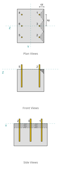
Перпендикулярная емкость:
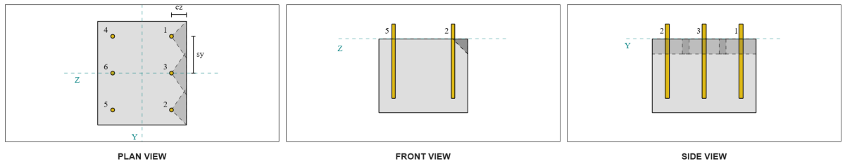
Из макета, Якоря 1 и 4 ближе всего к краю и имеют Самое короткое расстояние CA1. Использование этих значений CA1 для проецирования конусов отказа, Программное обеспечение определило эти якоря как одиночные якоря, Поскольку их прогнозируемые конусы не перекрываются. Поддержка также была определена как узкая член, Таким образом, расстояние CA1 используется непосредственно без модификации.
Давайте напомним, что сдвиг предполагается, что среди всех якорей распределяется среди всех якорей. Расчет для Vy shear нагрузки применяется к каждому отдельному якову:
\( V_{фаперп} = frac{V_Y}{n_a} = frac{2\,\текст{кип }}{6} = 0,33333,текст{кип } \)
Давайте рассмотрим Якорь 1. Максимальная прогнозируемая площадь одного якоря рассчитывается с использованием Аси 318-19 уравнение. 17.7.2.1.3.
\( A_{Vco} знак равно 4.5 (c_{A1, S1})^ 2 = 4.5 \раз (2\,\текст{в})^2 = 18,текст{в}^ 2 \)
Фактическая прогнозируемая область затем определяется по ширине и высоте прогнозируемого конуса сбоя.
\( B_{U} = min(c_{осталось,с1},\, 1.5c_{A1, S1}) + \мин(c_{право,с1},\, 1.5c_{A1, S1}) \)
\( B_{U} = min(10\,\текст{в},\, 1.5 \раз 2,текст{в}) + \мин(2\,\текст{в},\, 1.5 \раз 2,текст{в}) = 5,текст{в} \)
\( ЧАС_{U} = min(1.5c_{A1, S1},\, т_{концентрация}) = min(1.5 \раз 2,текст{в},\, 10\,\текст{в}) = 3,текст{в} \)
\( A_{U} = B_{U} ЧАС_{U} = 5,текст{в} \раз 3,текст{в} = 15,текст{в}^ 2 \)
Следующий шаг - использовать Уравнения 17.7.2.2.1a и 17.7.2.2.1b Рассчитать основную прочность на прорыв одного якоря. Руководящий потенциал принимается как меньшая ценность.
\( V_{b1} знак равно 7 \осталось( \гидроразрыва{\мин(а,\, 8D_A)}{D_A} \право)^{0.2} \SQRT{\гидроразрыва{D_A}{\текст{в}}} \лямбда_а sqrt{\гидроразрыва{f’_c}{\текст{фунтов на квадратный дюйм}}} \осталось( \гидроразрыва{c_{A1, S1}}{\текст{в}} \право)^{1.5} \,\текст{фунт-сила} \)
\( V_{b1} знак равно 7 \раз осталось( \гидроразрыва{\мин(8\,\текст{в},\, 8 \раз 0,5,текст{в})}{0.5\,\текст{в}} \право)^{0.2} \раз sqrt{\гидроразрыва{0.5\,\текст{в}}{1\,\текст{в}}} \раз 1 \раз sqrt{\гидроразрыва{3\,\текст{KSI}}{0.001\,\текст{KSI}}} \раз осталось( \гидроразрыва{2\,\текст{в}}{1\,\текст{в}} \право)^{1.5} \раз 0,001,текст{кип } \)
\( V_{b1} = 1,1623,текст{кип } \)
\( V_{Би 2} знак равно 9 \лямбда_а sqrt{\гидроразрыва{f’_c}{\текст{фунтов на квадратный дюйм}}} \осталось( \гидроразрыва{c_{A1, S1}}{\текст{в}} \право)^{1.5} \,\текст{фунт-сила} \)
\( V_{Би 2} знак равно 9 \раз 1 \раз sqrt{\гидроразрыва{3\,\текст{KSI}}{0.001\,\текст{KSI}}} \раз осталось( \гидроразрыва{2\,\текст{в}}{1\,\текст{в}} \право)^{1.5} \раз 0,001,текст{кип } = 1,3943,текст{кип } \)
\( V_b = min(V_{b1},\, V_{Би 2}) = min(1.1623\,\текст{кип },\, 1.3943\,\текст{кип }) = 1,1623,текст{кип } \)
следующий, в Параметры прорывной емкости определены. В Фактор эффекта края прорыва рассчитывается в соответствии с Аси 318-19 Пункт 17.7.2.4, и Коэффициент толщины рассчитывается в соответствии с Пункт 17.7.2.6.1.
\( \PSI_{ред,V} = минлево(1.0,\, 0.7 + 0.3 \осталось( \гидроразрыва{c_{A2, S1}}{1.5c_{A1, S1}} \право) \право) = минлево(1,\, 0.7 + 0.3 \раз осталось( \гидроразрыва{2\,\текст{в}}{1.5 \раз 2,текст{в}} \право) \право) знак равно 0.9 \)
\( \PSI_{час,V} = максвлево( \SQRT{ \гидроразрыва{1.5c_{A1, S1}}{т_{концентрация}} },\, 1.0 \право) = максвлево( \SQRT{ \гидроразрыва{1.5 \раз 2,текст{в}}{10\,\текст{в}} },\, 1 \право) знак равно 1 \)
В завершение, Аси 318-19 Пункт 17.7.2.1(а ) используется для определения бетонной прорывной способности одного якоря в сдвиге. Рассчитанная емкость для сдвига Vy в перпендикулярном направлении 0.69 кипы .
\( \фи V_{КБперп} = phi осталось( \гидроразрыва{A_{U}}{A_{Vco}} \право) \PSI_{ред,V} \PSI_{с,V} \PSI_{час,V} V_B \)
\( \фи V_{КБперп} знак равно 0.65 \раз осталось( \гидроразрыва{15\,\текст{в}^ 2}{18\,\текст{в}^ 2} \право) \раз 0.86 \раз 1 \раз 1 \раз 1,1623,текст{кип } = 0,56661,текст{кип } \)
Рассчитанная емкость для Vy shear в перпендикуляр направление 0.56 кипы .
Параллельная емкость:
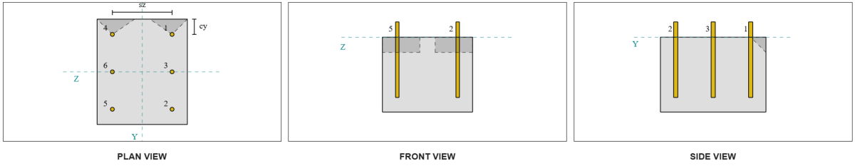
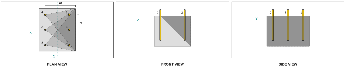
Отказ вдоль края параллельно нагрузке также возможен в этом сценарии, Итак бетонная прорывная емкость для параллельного края Должен быть определен. Рассматриваемые якоря или якоря выровнены с параллельным краем. следовательно, в CA1 Крайное расстояние измеряется от якоря до края вдоль Z-направления. На основе рисунка ниже, Проекции конуса сбоя перекрываются; следовательно, Якоря рассматриваются как группа.
Дело 1:
Дело 2:
Мы ссылаемся на Аси 318-19 инжир. R17.7.2.1b Для различных случаев, используемых при оценке якорных групп. В этой конструкции базовой плиты, сварные пластинки конкретно используются. Следовательно, Только Дело 2 проверяется.
Требуемая нагрузка для якорной группы в случае 2 принимается как Общая нагрузка на сдвиг.
\( V_{фапараллельно,case2} = V_y = 2,текст{кип } \)
При расчете пропускной способности дела 2 отказ, рассматриваемые якоря являются задние якоря. В следствии, Расстояние края CA1 измеряется от задней анкерной группы до края отказа.
С этим расстоянием CA1 и ориентацией на краю, Должно быть подтверждено, соответствует ли поддержка как узкий участник. Следующий Аси 318-19 Пункт 17.7.2.1.2, Программное обеспечение Skyciv Base Plate определило поддержку как узкий. Следовательно, в Модифицированное расстояние CA1 используется, который рассчитывается как 6.667 в.
Следуют те же шаги, что и в перпендикулярном случае: расчет Прогнозируемые области неудачи, в Основная сила прорыва в одиночку, и Параметры прорыва. Рассчитанные значения для каждого шага показаны ниже.
\( A_{Vco} знак равно 4.5 (c_{‘A1, G2})^ 2 = 4.5 \раз (6.6667\,\текст{в})^2 = 200,текст{в}^ 2 \)
\( A_{U} = B_{U} ЧАС_{U} = 14,текст{в} \раз 10,текст{в} = 140,текст{в}^ 2 \)
\( V_{b1} = 7.0733,текст{кип } \)
\( V_{Би 2} = 8.4853,текст{кип } \)
\( V_b = min(V_{b1},\, V_{Би 2}) = min(7.0733\,\текст{кип },\, 8.4853\,\текст{кип }) = 7.0733,текст{кип } \)
\( \PSI_{ред,V} знак равно 1.0 \)
\( \PSI_{час,V} знак равно 1.0 \)
Уравнение для способности параллельного края отличается от перпендикулярной емкости края. Аси 318-19 Пункт 17.7.2.1(с) применяется, где уравнение прорыва умножен на 2.
\( \фи V_{cbgпараллельный} знак равно 2 \phi остался( \гидроразрыва{A_{U}}{A_{Vco}} \право) \PSI_{ред,V} \PSI_{с,V} \PSI_{час,V} V_B \)
\( \фи V_{cbgпараллельный} знак равно 2 \раз 0.65 \раз осталось( \гидроразрыва{140\,\текст{в}^ 2}{200\текст{в}^ 2} \право) \раз 1 \раз 1 \раз 1 \раз 7.0733,текст{кип } = 6.4367,текст{кип } \)
Рассчитанная емкость для Vy shear в параллельный направление 6.43 кипы .
Теперь мы оцениваем перпендикулярные и параллельные сбои отдельно.
- Для перпендикулярного отказа от края, поскольку 0.33 кип < 0.56 кип , Программа прорыва сдвига в конструкции достаточный.
- Для параллельного отказа от края, поскольку 2 кип < 6.43 кип , Программа прорыва сдвига в конструкции достаточный.
Проверьте #3: Рассчитайте бетонную прорывную способность из -за сдвига VZ
Основная плита также подвергается VZ Shear, Таким образом, края сбоя перпендикулярно и параллельно сдвигу VZ должны быть проверены. Использование того же подхода, перпендикулярные и параллельные возможности рассчитываются как 2.45 кипы и 1.26 кипы , соответственно.
Перпендикулярный край:
Параллельный край:
Эти возможности затем сравниваются с требуемыми сильными сторонами.
- Для перпендикулярного отказа от края, поскольку 2 кип < 2.45 кип , пролавка бетонного сдвига достаточный.
- Для параллельного отказа от края, поскольку 0.33 кип < 1.26 кип , пролавка бетонного сдвига достаточный.
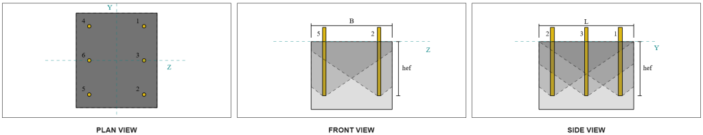
Проверьте #4: Рассчитайте бетонную емкость
В бетонный конус для сбоя тот же конус, используемый в проверке прорыва на растяжение. Чтобы рассчитать емкость сдвига, Номинальная прочность на растяжение отдельных якорей или якорной группы должна быть сначала определена. Подробные расчеты для проверки прорыва на растяжение уже рассмотрены в Примеры дизайна Skyciv для нагрузки натяжения.
Важно отметить, что определение якорной группы для сдвигового Pryout отличается от определения для прорыва сдвига. Следовательно, якоря в дизайне все еще должна быть проверена, чтобы определить, есть ли они действовать как группа или как одиночные якоря против неудачи. Классификация поддержки как Узкая секция также должен быть проверен и должен следовать тем же условиям, которые использовались для Прорыв напряжения.
Из расчетов Skyciv, в Прочность на номинальное растяжение якорной группы 12.772 кипы . С фактором KCP = 2, емкость дизайна:
\( \фи V_{КПГ} = ты к_{cp} N_{cbg} знак равно 0.65 \раз 2 \раз 12.772 \,\текст{кип } = 16.604,текст{кип } \)
Требуемая сила - это Результирующее из приложенных сдвиговых нагрузок. Поскольку все якоря принадлежат одной группе, Общий результирующий сдвиг назначается группе.
\( V_{делать} = кврт{(V_Y)^ 2 + (V_Z.)^ 2} = кврт{(2\,\текст{кип })^ 2 + (2\,\текст{кип })^ 2} = 2,8284,текст{кип } \)
\( V_{делать} = слева( \гидроразрыва{V_{делать}}{n_a} \право) n_{а ,g1} = слева( \гидроразрыва{2.8284\,\текст{кип }}{6} \право) \раз 6 = 2,8284,текст{кип } \)
Поскольку общая нагрузка на сдвиг меньше, чем ведущая группа, 2.82 кипы < 18.976 кипы , емкость дизайна достаточный.
Проверьте #5: Рассчитайте сдвиг стержней стержней
Напомним, что в этом примере дизайна, сдвиг распределяется по всем якорям. Следовательно, общая нагрузка на сдвиг на якорь является результирующей его доли нагрузки VY и его доли VZ нагрузки.
\( в_{делать,и} = frac{V_Y}{n_a} = frac{2\,\текст{кип }}{6} = 0,33333,текст{кип } \)
\( в_{делать,с участием} = frac{V_Z.}{n_a} = frac{2\,\текст{кип }}{6} = 0,33333,текст{кип } \)
\( V_{делать} = кврт{(в_{делать,и})^ 2 + (в_{делать,с участием})^ 2} \)
\( V_{делать} = кврт{(0.33333\,\текст{кип })^ 2 + (0.33333\,\текст{кип })^ 2} = 0,4714,текст{кип } \)
Это дает Напряжение сдвига на якорный стержень так как:
\( f_v = frac{V_{делать}}{A_{стержень}} = frac{0.4714\,\текст{кип }}{0.19635\,\текст{в}^ 2} = 2.4008,текст{KSI} \)
Потому что присутствует шайба, ан эксцентричная нагрузка на сдвиг индуцируется в якорном стержне. Эксцентриситет принимается как половина расстояния, измеряемого от верхней части бетонной опоры в центр шайбы пластины, Учет толщины опорной плиты. Обратиться к Руководство по проектированию AISC 1, 3Rd Edition Раздел 4.3.3.
\( е = 0.5 \осталось( \гидроразрыва{т_{пту}}{2} + т_{бп} \право) знак равно 0.5 \раз осталось( \гидроразрыва{0.25\,\текст{в}}{2} + 0.75\,\текст{в} \право) = 0,4375,текст{в} \)
Момент от эксцентричного сдвига затем выражается как осевое напряжение в якорном стержне. Использование модуля раздела, осевое напряжение из -за этого момента рассчитывается как:
\( Z_{стержень} = frac{\число Пи}{32} (D_A)^3 = фрак{\число Пи}{32} \раз (0.5\,\текст{в})^3 = 0,012272,текст{в}^3 \)
\( f_t = frac{V_{делать} е}{Z_{стержень}} = frac{0.4714\,\текст{кип } \раз 0,4375,текст{в}}{0.012272\,\текст{в}^3} = 16.806,текст{KSI} \)
ACI ACI ANCAR STEAR SHEAR:
Следующий Аси 318-19 Пункт 17.7.1, Затем определяется прочность на конструкцию. А 0.8 Коэффициент уменьшения применяется из -за наличия затирки. Следовательно, дизайнерская емкость:
\( \фи V_{к,здесь} знак равно 0.8 \фи 0.6 A_{я знаю,v} f_{ута} знак равно 0.8 \раз 0.65 \раз 0.6 \раз 0,1419текст{в}^2 times 90text{KSI} = 3.9845текст{кип } \)
Как альтернатива, в Skyciv Base Plate Software позволяет 0.8 Упрощение отключено, и используйте фактическую толщину затиркой накладки в расчетах. В таком случае, Общая эксцентричность включает в себя затирку, и комбинированная сдвиг и прочность на сдвиг определяется в соответствии с положениями AISC.
AISC ANCAR SHEAR SHEAR:
Первый, в номинальные стрессы и растягивающие напряжения определяются для стержня A325.
\( F_{нв} знак равно 0.45 F_{U,anc} знак равно 0.45 \раз 120\ \текст{KSI} знак равно 54\ \текст{KSI} \)
\( F_{нт} знак равно 0.75 F_{U,anc} знак равно 0.75 \раз 120\ \текст{KSI} знак равно 90\ \текст{KSI} \)
Метод AISC использует Aisc 360-22 уравнение. J3-3A, который может быть выражен, чтобы включить эффекты осевого напряжения. Это осуществляется следующим образом.
\( F’_{нв} = min left( 1.3 F_{нв} – \осталось( \гидроразрыва{F_{нв}}{\Phi f_{нт}} \право) ф_т,\; F_{нв} \право) \)
\( F’_{нв} = min left( 1.3 \раз 54\ \текст{KSI} – \осталось( \гидроразрыва{54\ \текст{KSI}}{0.75 \раз 90\ \текст{KSI}} \право) \раз 16.806\ \текст{KSI},\; 54\ \текст{KSI} \право) знак равно 54\ \текст{KSI} \)
Программа сдвига сдвига из метода AISC затем рассчитывается как:
\( \фи Р_{N,\Mathrm{AISC}} = фи F’_{нв} A_{стержень} знак равно 0.75 \раз 54\ \текст{KSI} \раз 0.19635\ \текст{в}^ 2 = 7.9522\)
Для обеспечения покрытия обоих методов, руководящий потенциал принимается как меньший из двух, который 3.98 кип .
\( \фи V_n = min left( \фи V_{к,здесь},\; \фи Р_{N,\Mathrm{AISC}} \право) = min (3.9845\ \текст{кип },\; 7.9522\ \текст{кип }) знак равно 3.9845\ \текст{кип } \)
Поскольку нагрузка на сдвиг на якорный стержень меньше, чем руководящая анкерная емкость в сдвиге, 0.47 кип < 3.98 кип , Программа сдвига стержней стержней дизайна достаточный.
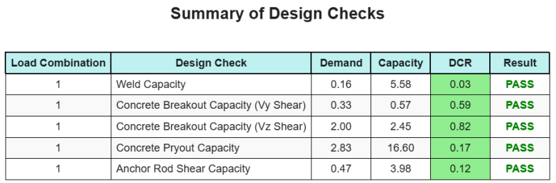
Резюме дизайна
В Программное обеспечение для дизайна базовой плиты Skyciv может автоматически генерировать пошаговый отчет расчета для этого примера проекта. Это также предоставляет краткую информацию о выполненных чеках и их полученных соотношениях, Облегчение информации для понимания с первого взгляда. Ниже приведена примерная сводная таблица, который включен в отчет.
Образец Skyciv
Посмотрите уровень детализации и ясности, который вы можете ожидать от отчета о конструкции базовой пластины SkyCiv.. Отчет включает все ключевые проверки проекта., уравнения, и результаты представлены в ясном и легко читаемом формате.. Полностью соответствует стандартам проектирования.. Нажмите ниже, чтобы просмотреть образец отчета, созданного с помощью калькулятора базовой плиты SkyCiv..
Покупка программного обеспечения для базовой пластины
Купите полную версию модуля дизайна базовой плиты без каких -либо других модулей Skyciv. Это дает вам полный набор результатов для дизайна базовой плиты, в том числе подробные отчеты и больше функциональности.