Пример дизайна базовой пластины с использованием AISC 360-22 и ACI 318-19
Запись о проблеме
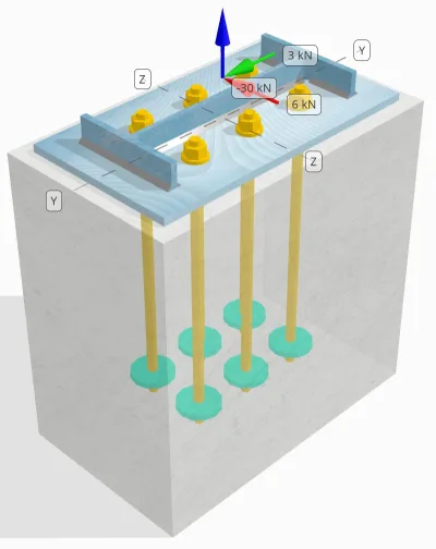
Определите, достаточно ли спроектированное соединение колонны с опорной плитой для 30 кН, растягивающая нагрузка, 3 кН Vy сдвиговая нагрузка, и 6 кН Vz сдвиговая нагрузка.
Данные данных
Столбец:
Раздел столбца: Ш14x30
Область столбца: 5709.7 мм2
Материал столбца: A992
Опорная плита:
Размеры опорной плиты: 250 мм х 250 мм
Толщина опорной плиты: 12 мм
Материал опорной плиты: A992
Раствор:
Толщина затирки: 0 мм
бетон:
Бетонные размеры: 300 мм х 500 мм
Бетонная толщина: 500 мм
Бетонный материал: 20.7 МПа
Потрескался или не снят: Потрескался
Якоря:
Диаметр якоря: 16 мм
Эффективная длина встраивания: 400 мм
Якорная концовка: Круглая пластина
Встроенный диаметр пластины: 70 мм
Встроенная тарелка толщина: 10 мм
Стальной материал: F1554 Гр.55
Резьба в плоскости сдвига: Включено
Швы:
Размер сварного шва: 7 мм
Классификация металла наполнителя: Е70ХХ
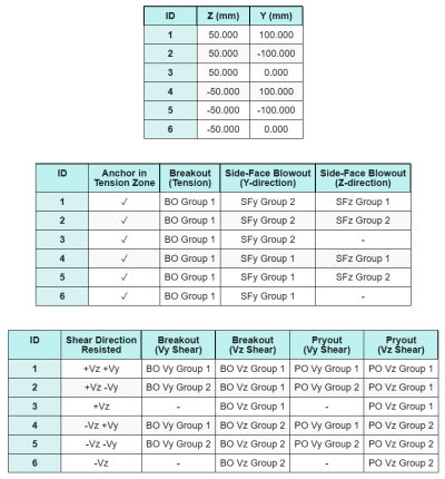
Якоря данных (из Skyciv Calculator):
Модель в бесплатном инструменте SkyCiv
Смоделируйте конструкцию опорной плиты, указанную выше, с помощью нашего бесплатного онлайн-инструмента сегодня.! Регистрация не требуется.
Заметка
Целью этого примера проектирования является демонстрация пошаговых расчетов для проверки несущей способности, включающей одновременные сдвиговые и осевые нагрузки.. Некоторые из необходимых проверок уже обсуждались в предыдущих примерах проектирования.. Пожалуйста, перейдите по ссылкам, представленным в каждом разделе..
Пошаговые расчеты
Проверьте #1: Рассчитайте емкость сварки
Для определения прочности сварного шва при одновременной нагрузке, сначала нам нужно рассчитать потребность в сварке из-за сдвиговая нагрузка и потребность в сварке из-за растягивающая нагрузка. Вы можете обратиться к этому ссылка на сайт для процедуры получения требований к сварному шву на сдвиг, и это ссылка на сайт для требований к сварке натяжением.
Для этого дизайна, в спрос на сварку в сети из-за растягивающей нагрузки оказывается следующим образом, где напряжение выражается как усилие на единицу длины.
\(р_{U,\текст{сеть}} = frac{Т_{U,\текст{якорь}}}{l_{\текст{эфф}}} = frac{5\ \текст{кН}}{93.142\ \текст{мм}} знак равно 0.053681\ \текст{кН / мм}\)
более того, в сварочное напряжение в любой части сечения колонны под действием сдвиговой нагрузки определяется как:
\(в_{уй} = frac{V_Y}{L_{\текст{сварка}}} = frac{3\ \текст{кН}}{1250.7\ \текст{мм}} знак равно 0.0023987\ \текст{кН / мм}\)
\(в_{к} = frac{V_Z.}{L_{\текст{сварка}}} = frac{6\ \текст{кН}}{1250.7\ \текст{мм}} знак равно 0.0047973\ \текст{кН / мм}\)
Поскольку существует сочетание растягивающих и сдвиговых нагрузок. сеть, нам нужно получить результат. Выразив это как силу на единицу длины, у нас есть:
\(r_u = sqrt{(р_{U,\текст{сеть}})^ 2 + (в_{уй})^ 2 + (в_{к})^ 2}\)
\(r_u = sqrt{(0.053681\ \текст{кН / мм})^ 2 + (0.0023987\ \текст{кН / мм})^ 2 + (0.0047973\ \текст{кН / мм})^ 2}\)
\(р_у = 0.053949\ \текст{кН / мм}\)
Для фланцы, присутствуют только касательные напряжения. таким образом, результат:
\(r_u = sqrt{(в_{уй})^ 2 + (в_{к})^ 2}\)
\(r_u = sqrt{(0.0023987\ \текст{кН / мм})^ 2 + (0.0047973\ \текст{кН / мм})^ 2} знак равно 0.0053636\ \текст{кН / мм}\)
следующий, мы рассчитываем сварочные мощности. Для фланца, мы определяем угол θ API рендерера SkyCiv ВЗ и Vy грузы.
\( \тета = tan^{-1}\!\осталось(\гидроразрыва{в_{уй}}{в_{к}}\право) = tan^{-1}\!\осталось(\гидроразрыва{0.0023987\ \текст{кН / мм}}{0.0047973\ \текст{кН / мм}}\право) знак равно 0.46365\ \текст{Работа} \)
следовательно, в КДС коэффициент и мощность сварки рассчитываются с использованием Aisc 360-22 уравнение. J2-5 и уравнение. J2-4.
\(к_{дюймовый} знак равно 1.0 + 0.5(\без(\тэта))^{1.5} знак равно 1 + 0.5 \раз (\без(0.46365\ \текст{Работа}))^{1.5} знак равно 1.1495\)
\(\phi r_{N,флг} = фи,0.6,F_{Экспресс}\,Е_ш,к_{дюймовый} знак равно 0.75 \раз 0.6 \раз 480\ \текст{МПа} \раз 4.95\ \текст{мм} \раз 1.1495 знак равно 1.2291\ \текст{кН / мм}\)
Для Интернета, мы вычисляем угол θ используя другую формулу. Обратите внимание, что Ух ты используется в формуле, поскольку представляет нагрузку, параллельную оси сварного шва..
\( \тета = cos^{-1}\!\осталось(\гидроразрыва{в_{уй}}{р_у}\право) = соз ^{-1}\!\осталось(\гидроразрыва{0.0023987\ \текст{кН / мм}}{0.053949\ \текст{кН / мм}}\право) знак равно 1.5263\ \текст{Работа} \)
С использованием Aisc 360-22 уравнение. J2-5 и уравнение. J2-4, в КДС коэффициент и результирующая прочность сварного шва определяются таким же образом..
\(к_{дюймовый} знак равно 1.0 + 0.5(\без(\тэта))^{1.5} знак равно 1 + 0.5 \раз (\без(1.5263\ \текст{Работа}))^{1.5} знак равно 1.4993\)
\(\phi r_{N,сеть} = фи,0.6,F_{Экспресс}\,Е_ш,к_{дюймовый} знак равно 0.75 \раз 0.6 \раз 480\ \текст{МПа} \раз 4.95\ \текст{мм} \раз 1.4993 знак равно 1.603\ \текст{кН / мм}\)
наконец, мы выполняем чеки из недрагоценных металлов как для колонны, так и для опорной плиты, затем получите определяющую емкость основного металла.
\( \phi r_{Nbm,полковник} = фи,0.6,F_{U,полковник}\,т_{полковник,половина} знак равно 0.75 \раз 0.6 \раз 448.2\ \текст{МПа} \раз 3.429\ \текст{мм} знак равно 0.6916\ \текст{кН / мм} \)
\( \phi r_{Nbm,бп} = фи,0.6,F_{U,бп}\,т_{бп} знак равно 0.75 \раз 0.6 \раз 400\ \текст{МПа} \раз 12\ \текст{мм} знак равно 2.1595\ \текст{кН / мм} \)
\( \phi r_{Nbm} = минбольшой(\phi r_{Nbm,бп},\ \phi r_{Nbm,полковник}\большой) = min(2.1595\ \текст{кН / мм},\ 0.6916\ \текст{кН / мм}) знак равно 0.6916\ \текст{кН / мм} \)
Затем мы сравниваем мощность углового шва и емкость основного металла для требований к сварке на полки и стенка отдельно.
поскольку 0.053949 кН / мм < 0.6916 кН / мм, емкость сварки достаточный.
Проверьте #2: Рассчитайте емкость сгибки на основе нагрузки
Пример расчета предела текучести опорной плиты при изгибе уже обсуждался в разделе «Пример расчета опорной плиты на растяжение».. Пожалуйста, перейдите по этой ссылке для пошагового расчета..
Проверьте #3: Рассчитать емкость привязки якоря растягиваемой
Пример расчета прочности анкерного стержня на растяжение уже обсуждался в разделе «Пример расчета опорной плиты на растяжение».. Пожалуйста, перейдите по этой ссылке для пошагового расчета.. Пожалуйста, перейдите по этой ссылке для пошагового расчета..
Проверьте #4: Рассчитайте бетонную прорывную емкость при натяжении
Пример расчета прочности бетона на разрыв при растяжении уже обсуждался в разделе «Пример расчета опорной плиты на растяжение».. Пожалуйста, перейдите по этой ссылке для пошагового расчета.. Пожалуйста, перейдите по этой ссылке для пошагового расчета..
Проверьте #5: Рассчитать способность выдвижения якоря
Пример расчета способности анкера к выдергиванию уже обсуждался в разделе «Пример расчета опорной плиты на растяжение».. Пожалуйста, перейдите по этой ссылке для пошагового расчета.. Пожалуйста, перейдите по этой ссылке для пошагового расчета..
Проверьте #6: Рассчитайте встроенную гибкую емкость
Пример расчета для дополнительной проверки способности закладной пластины к изгибу уже обсуждался в разделе «Пример расчета опорной плиты на растяжение».. Пожалуйста, перейдите по этой ссылке для пошагового расчета..
Проверьте #7: Рассчитайте пропускную способность в направлении y-направления
Чтобы рассчитать Боковой выброс (СФБО) вместимость, сначала мы определяем общую сумму сила натяжения на якорях, ближайших к краю. Для этой проверки, оценим пропускную способность ребра по Y-направление.
Поскольку проекции конуса разрушения СФБО по направлению Y перекрываются, якоря рассматриваются как Якорная группа.
Общая потребность в натяжении якорной группы рассчитывается как:
\(N_{делать} = слева(\гидроразрыва{N_x}{n_{а ,T}}\право) n_{и,g1} = слева(\гидроразрыва{30\ \текст{кН}}{6}\право) \раз 3 знак равно 15\ \текст{кН}\)
следующий, Мы определяем краевые расстояния:
\(c_{с участием,\мин} = min(c_{\текст{осталось},g1},\ c_{\текст{право},g1}) = min(100\ \текст{мм},\ 200\ \текст{мм}) знак равно 100\ \текст{мм}\)
\(c_{и,\мин} = min(c_{\текст{верхняя},g1},\ c_{\текст{низ},g1}) = min(150\ \текст{мм},\ 150\ \текст{мм}) знак равно 150\ \текст{мм}\)
Использование этих краевых расстояний, мы рассчитываем емкость якорной группы в соответствии с Аси 318-19 уравнение. (17.6.4.1).
\(N_{как} = слева(\гидроразрыва{1 + \dfrac{c_{и,\мин}}{c_{с участием,\мин}}}{4} + \гидроразрыва{S_{сумма,и,g1}}{6\,c_{с участием,\мин}}\право)\раз 13 \раз осталось(\гидроразрыва{c_{с участием,\мин}}{1\ \текст{мм}}\право)\раз sqrt{\гидроразрыва{A_{brg}}{\текст{мм}^ 2}}\ \лямбда_а sqrt{\гидроразрыва{е_с}{\текст{МПа}}}\раз 0.001\ \текст{кН}\)
\(N_{как} = слева(\гидроразрыва{1 + \dfrac{150\ \текст{мм}}{100\ \текст{мм}}}{4} + \гидроразрыва{200\ \текст{мм}}{6\раз 100\ \текст{мм}}\право)\раз 13 \раз осталось(\гидроразрыва{100\ \текст{мм}}{1\ \текст{мм}}\право)\раз sqrt{\гидроразрыва{3647.4\ \текст{мм}^ 2}{1\ \текст{мм}^ 2}}\раз 1 \раз sqrt{\гидроразрыва{20.68\ \текст{МПа}}{1\ \текст{МПа}}}\раз 0.001\ \текст{кН}\)
\(N_{как} знак равно 342.16\ \текст{кН}\)
В исходном уравнении, коэффициент уменьшения применяется, когда расстояние между анкерами меньше 6ок₁, при условии, что анкеры с головками имеют достаточное расстояние от края. тем не мение, в этом примере дизайна, поскольку ок₂ < 3ок₁, Калькулятор SkyCiv применяет дополнительный коэффициент уменьшения для учета уменьшенной краевой емкости..
В завершение, в расчетная мощность СФБО является:
\(\phi N_{как} = фи,N_{как} знак равно 0.7 \раз 342.16\ \текст{кН} знак равно 239.51\ \текст{кН}\)
поскольку 15 кН < 239.51 кН, пропускная способность SFBO в направлении Y равна достаточный.
Проверьте #8: Рассчитайте пропускную способность в направлении z в направлении z
Следуя тому же подходу, что и в Проверьте #7, общее требование натяжения якорной группы для якорей, ближайших к Z-направление край это:
\(N_{делать} = слева(\гидроразрыва{N_x}{n_{а ,T}}\право)n_{с участием,g1} = слева(\гидроразрыва{30\ \текст{кН}}{6}\право)\раз 2 знак равно 10\ \текст{кН}\)
В краевые расстояния рассчитываются как:
\(c_{и,\мин} = min(c_{\текст{верхняя},g1},\ c_{\текст{низ},g1}) = min(150\ \текст{мм},\ 350\ \текст{мм}) знак равно 150\ \текст{мм}\)
\(c_{с участием,\мин} = min(c_{\текст{осталось},g1},\ c_{\текст{право},g1}) = min(100\ \текст{мм},\ 100\ \текст{мм}) знак равно 100\ \текст{мм}\)
В номинальная мощность СФБО затем определяется как:
\(N_{как} = слева(\гидроразрыва{1 + \dfrac{c_{с участием,\мин}}{c_{и,\мин}}}{4} + \гидроразрыва{S_{сумма,с участием,g1}}{6\,c_{и,\мин}}\право)\раз 13 \раз осталось(\гидроразрыва{c_{и,\мин}}{1\ \текст{мм}}\право)\раз sqrt{\гидроразрыва{A_{brg}}{\текст{мм}^ 2}}\ \лямбда_а sqrt{\гидроразрыва{е_с}{\текст{МПа}}}\раз 0.001\ \текст{кН}\)
\(N_{как} = слева(\гидроразрыва{1 + \dfrac{100\ \текст{мм}}{150\ \текст{мм}}}{4} + \гидроразрыва{100\ \текст{мм}}{6\раз 150\ \текст{мм}}\право)\раз 13 \раз осталось(\гидроразрыва{150\ \текст{мм}}{1\ \текст{мм}}\право)\раз sqrt{\гидроразрыва{3647.4\ \текст{мм}^ 2}{1\ \текст{мм}^ 2}}\раз 1 \раз sqrt{\гидроразрыва{20.68\ \текст{МПа}}{1\ \текст{МПа}}}\раз 0.001\ \текст{кН}\)
\(N_{как} знак равно 282.65\ \текст{кН}\)
Поскольку краевое расстояние ок₂ все еще меньше, чем 3ок₁, применяется тот же модифицированный коэффициент уменьшения.
В завершение, в расчетная мощность СФБО является:
\(\phi N_{как} = фи,N_{как} знак равно 0.7 \раз 282.65\ \текст{кН} знак равно 197.86\ \текст{кН}\)
поскольку 10 кН < 197.86 кН, пропускная способность СФБО по Z-направление является достаточный.
Проверьте #9: Рассчитать прорывную способность (Vy shear)
Пример расчета способности бетона к прорыву при сдвиге Vy уже обсуждался в разделе «Пример расчета опорной плиты при сдвиге».. Пожалуйста, перейдите по этой ссылке для пошагового расчета..
Проверьте #10: Рассчитать прорывную способность (VZ Shear)
Пример расчета способности бетона к прорыву при сдвиге Vy уже обсуждался в разделе «Пример расчета опорной плиты при сдвиге».. Пожалуйста, перейдите по этой ссылке для пошагового расчета..
Проверьте #11: Рассчитать мощность выдергивания (Vy shear)
Пример расчета устойчивости бетона к разрушению при отрыве из-за сдвига Vy уже обсуждался в примере расчета опорной плиты на сдвиг.. Пожалуйста, перейдите по этой ссылке для пошагового расчета..
Проверьте #12: Рассчитать мощность выдергивания (VZ Shear)
Пример расчета устойчивости бетона к разрушению при отрыве из-за сдвига Vy уже обсуждался в примере расчета опорной плиты на сдвиг.. Пожалуйста, перейдите по этой ссылке для пошагового расчета..
Проверьте #13: Рассчитайте сдвиг стержней стержней
Пример расчета устойчивости анкерного стержня к сдвигу уже обсуждался в разделе «Пример расчета опорной плиты на сдвиг».. Пожалуйста, перейдите по этой ссылке для пошагового расчета..
Проверьте #14: Рассчитайте сдвиг и осевую нагрузку анкерного стержня (Aisc)
Определить устойчивость анкерного стержня при комбинированных сдвиговых и осевых нагрузках., мы используем Aisc 360-22 уравнение. J3-3A. В этом калькуляторе, уравнение переформулировано, чтобы вместо этого выразить результат как модифицированную прочность на сдвиг..
В спрос на сдвиг определяется как сдвигающая нагрузка на анкер.
\(V_{делать} = В_{делать} знак равно 2.5\ \текст{кН}\)
В спрос на напряжение выражается как растягивающее напряжение в якорной штанге.
\(f_{из} = frac{N_{делать}}{A_{стержень}} = frac{5\ \текст{кН}}{201.06\ \текст{мм}^ 2} знак равно 24.868\ \текст{МПа}\)
В модифицированная способность к сдвигу анкерного стержня затем рассчитывается как:
\(F’_{нв} = мин!\осталось(1.3\,F_{нв} – \осталось(\гидроразрыва{F_{нв}}{\Phi f_{нт}}\право) f_{из},\; F_{нв}\право)\)
\(F’_{нв} = мин!\осталось(1.3\раз 232.69\ \текст{МПа} – \осталось(\гидроразрыва{232.69\ \текст{МПа}}{0.75\раз 387.82\ \текст{МПа}}\право)\раз 24.868\ \текст{МПа},\; 232.69\ \текст{МПа}\право) знак равно 232.69\ \текст{МПа}\)
Затем мы умножаем эту силу на якорная зона с использованием Aisc 360-22 уравнение. J3-2.
\(\фи Р_{N,\текст{AISC}} = фи F’_{нв} A_{\текст{стержень}} знак равно 0.75 \раз 232.69\ \текст{МПа} \раз 201.06\ \текст{мм}^ 2 = 35.09\ \текст{кН}\)
поскольку 2.5 кН < 35.09 кН, емкость анкерного стержня достаточный.
Проверьте #15: Рассчитать проверки взаимодействия (Аси)
При проверке прочности анкерного стержня при комбинированных сдвигающих и растягивающих нагрузках с помощью Аси, применяется другой подход. Для полноты, мы также выполняем Проверки взаимодействия ACI в этом расчете, которые включают в себя другие конкретные проверки взаимодействия также.
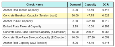
Вот результат коэффициенты для всех проверок натяжения ACI:
И вот что получилось соотношения для всех проверок на сдвиг ACI:
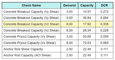
Мы получаем чек с наибольшим коэффициентом и сравниваем его с максимальным коэффициентом взаимодействия, используя Аси 318-19 уравнение. 17.8.3.
\(Я_{интервал} = frac{N_{делать}}{\фи Н_н} + \гидроразрыва{V_{делать}}{\фи В_н} = frac{30}{47.749} + \гидроразрыва{6}{17.921} знак равно 0.96308\)
поскольку 0.96 < 1.2, проверка взаимодействия достаточный.
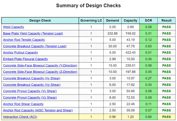
Резюме дизайна
В Программное обеспечение для дизайна базовой плиты Skyciv может автоматически генерировать пошаговый отчет расчета для этого примера проекта. Это также предоставляет краткую информацию о выполненных чеках и их полученных соотношениях, Облегчение информации для понимания с первого взгляда. Ниже приведена примерная сводная таблица, который включен в отчет.
Образец Skyciv
Посмотрите уровень детализации и ясности, который вы можете ожидать от отчета о конструкции базовой пластины SkyCiv.. Отчет включает все ключевые проверки проекта., уравнения, и результаты представлены в ясном и легко читаемом формате.. Полностью соответствует стандартам проектирования.. Нажмите ниже, чтобы просмотреть образец отчета, созданного с помощью калькулятора базовой плиты SkyCiv..
Покупка программного обеспечения для базовой пластины
Купите полную версию модуля дизайна базовой плиты без каких -либо других модулей Skyciv. Это дает вам полный набор результатов для дизайна базовой плиты, в том числе подробные отчеты и больше функциональности.