CSA S16 kullanarak taban plaka tasarımı örneği:19 ve CSA A23.3:19
Sorun Bildirimi
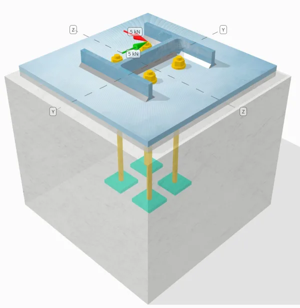
Tasarlanan sütun-tabaka plaka bağlantısının bir Sen = 5-kn ve VZ = 5-KN kesme yükleri.
Verilen Veriler
Sütun:
Sütun bölümü: HP200x54
Sütun alanı: 6840.0 mm2
Sütun malzemesi: 350W
Taban plakası:
Taban plaka boyutları: 400 mm x 400 mm
Taban plakası kalınlığı: 13 mm
Taban plaka malzemesi: 300W
Izgara:
Harç Kalınlığı: 13 mm
Somut:
Somut boyutlar: 450 mm x 450 mm
Beton kalınlığı: 380 mm
Beton malzeme: 20.68 MPa
Çatlamış veya çatlaksız: Çatlak
Çapa:
Çapa: 12.7 mm
Etkili gömme uzunluğu: 300 mm
Plaka yıkayıcı kalınlığı: 0 mm
Plaka yıkayıcı bağlantısı: Hayır
Kaynaklar:
kaynak boyutu: 8 mm
Dolgu Metal Sınıflandırması: E43xx
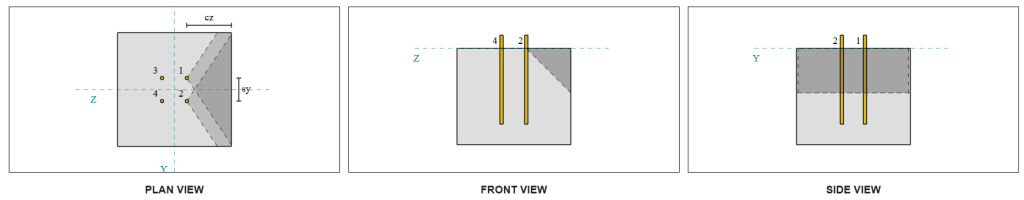
Çapa Verileri (itibaren SkyCiv Hesap Makinesi):
SkyCiv Ücretsiz Aracındaki Model
Ücretsiz çevrimiçi aracımızı kullanarak yukarıdaki taban plakası tasarımını bugün modelleyin! Kayıt olmanıza gerek yok.
Tanımlar
Yük yolu:
Tasarım şu şekildedir: CSA A23.3:2019 standartlar ve tavsiyeler AISC Tasarım Kılavuzu 1, 3Rd Edition. Kolona uygulanan kesme yükleri kaynaklar vasıtasıyla taban plakasına aktarılır., ve ardından destek betonuna çapa çubukları. Bu örnekte sürtünme ve kesme pabuçları dikkate alınmaz, Bu mekanizmalar mevcut yazılımda desteklenmediğinden.
Varsayılan olarak, NS uygulanan kesme yükü tüm ankrajlara dağıtılır, ya kaynaklı plaka rondelalarının kullanılmasıyla ya da diğer mühendislik araçlarıyla. Her bir ankrajın taşıdığı yük üç değer kullanılarak belirlenir. (3) belirtilen durumlarda CSA A23.3:2019 Madde D.7.2.1 ve Şekil D.13. Her bir ankraj daha sonra yükü aşağıdaki destekleyici betona aktarır.. Yük aktarımı varsayımlarında sürekliliği sağlamak için ankraj çeliği kesme dayanımı kontrol edilirken bu referanslara uygun yük dağılımı da kullanılır..
Alternatif olarak, yazılım basitleştirilmiş ve daha ihtiyatlı bir varsayıma izin verir, nerede tüm kesme yükü yalnızca yüklü kenara en yakın ankrajlara atanır. Bu durumda, kesme kapasitesi kontrolü yalnızca bu kenar ankrajlarında gerçekleştirilir, Potansiyel kayma kırılmasının ihtiyatlı bir şekilde ele alınmasının sağlanması.
Çapa:
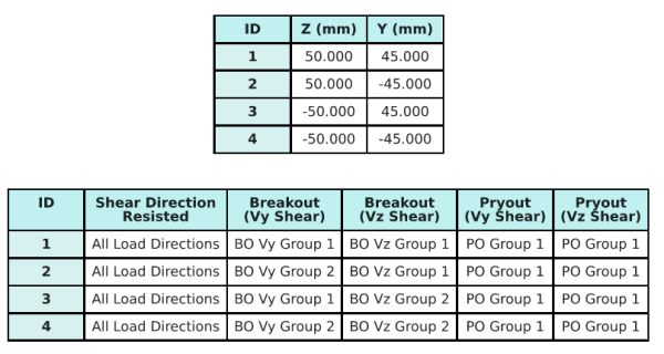
NS SkyCiv Taban Plakası Tasarım Yazılımı Hangi çapaların değerlendirmek için bir çapa grubunun parçası olduğunu belirleyen sezgisel bir özellik içerir. beton kesme kırılması ve Beton Kesme Pryout başarısızlık.
Bir çapa örtüşen öngörülen direnç alanlarına sahip iki veya daha fazla ankraj olarak tanımlanır. Bu durumda, Çapalar birlikte hareket eder, ve birleşik dirençleri gruptaki uygulanan yüke karşı kontrol edilir.
Bir tek çapa Öngörülen direnç alanı başka biriyle örtüşmeyen bir çapa olarak tanımlanır.. Bu durumda, Çapa tek başına hareket eder, ve bu çapa üzerindeki uygulanan kesme kuvveti doğrudan bireysel direncine göre kontrol edilir.
Bu ayrım, kayma ile ilgili arıza modlarını değerlendirirken yazılımın hem grup davranışını hem de bireysel çapa performansını yakalamasını sağlar..
Adım adım hesaplamalar
Soğuk şekillendirilmiş elemanlar aşağıdakilere uygun olarak tasarlanırken #1: Kaynak kapasitesini hesapla
İlk adım hesaplamaktır Toplam kaynak uzunluğu kesmeye direnmek için mevcut. Toplam kaynak uzunluğu, Kaynak , her taraftaki kaynakların toplanmasıyla elde edilir.
\( L_{kaynak} = 2b_f + 2(d_{seri} – 2T_F – 2r_{seri}) + 2(B_F – t_w – 2r_{seri}) \)
\( L_{kaynak} = 2 \çarpı 207,text{mm} + 2 \zamanlar (204,\Metin{mm} – 2 \çarpı 11,3,text{mm} – 2 \çarpı 9,7,text{mm}) + 2 \zamanlar (207,\Metin{mm} – 11.3,\Metin{mm} – 2 \çarpı 9,7,text{mm}) = 1090,6,metin{mm} \)
Bu kaynak uzunluğunu kullanma, y'de uygulanan kesme kuvvetleri- ve z-yönleri ortalamayı belirlemek için bölünür birim uzunluk başına kesme kuvveti her yönde:
\( v_{fy} = frac{V_y}{L_{kaynak}} = frac{5,\Metin{kN}}{1090.6,\Metin{mm}} = 0,0045846,text{kN/mm} \)
\( v_{fz} = frac{V_Z}{L_{kaynak}} = frac{5,\Metin{kN}}{1090.6,\Metin{mm}} = 0,0045846,text{kN/mm} \)
NS ortaya çıkan kesme talebi birim uzunluk başına karelerin toplamının karekökü kullanılarak belirlenir (SRSS) yöntem.
\( v_f = sqrt{\ayrıldı((v_{fy})^2sağ) + \ayrıldı((v_{fz})^2sağ)} \)
\( v_f = sqrt{\ayrıldı((0.0045846,\Metin{kN/mm})^2sağ) + \ayrıldı((0.0045846,\Metin{kN/mm})^2sağ)} = 0,0064836,text{kN/mm} \)
Sonraki, kaynak kapasitesi kullanılarak hesaplanır CSA S16:19 Madde 13.13.2.2, olarak alınan yön mukavemeti katsayısı ile muhafazakar olmak gerekirse kds=1.0. Hem flanşlarda hem de ağda 8 mm'lik bir kaynak için kaynak kapasitesi:
\( v_r = 0,67phi t_{w,Ana farkın, kiriş flanşlarının destek kolonuna bağlantısında yattığını fark edebilirsiniz.}X_u = 0.67 \zamanlar 0.67 \çarpı 5,657,text{mm} \çarpı 430,text{MPa} = 1,092,metin{kN/mm} \)
\( v_r = 0,67phi t_{w,ağ}X_u = 0.67 \zamanlar 0.67 \çarpı 5,657,text{mm} \çarpı 430,text{MPa} = 1,092,metin{kN/mm} \)
yönetim fileto kaynak kapasitesi dır-dir:
\( v_{r,fileto} = min(v_r, v_i) = min(1.092\,\Metin{kN/mm}, 1.092\,\Metin{kN/mm}) = 1,092,metin{kN/mm} \)
Bu kaynaklı bağlantı için, elektrot gücü fazla eşleşmez baz metalin güçlü yönleri. Bu nedenle, ana metal kontrolü geçerli değildir ve yapılmasına gerek yoktur.
Dan beri 0.0064 kN/mm < 1.092 kN/mm, çarpanlara ayrılmış kaynak kapasitesi yeterli.
Soğuk şekillendirilmiş elemanlar aşağıdakilere uygun olarak tasarlanırken #2: VY kesme nedeniyle beton kırılma kapasitesini hesaplayın
Dik Kenar Kapasitesi:
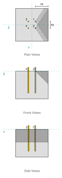
Arıza konilerini yansıtmak için her bir çapanın ca1 değerlerini kullanma, yazılım bu ankrajların arıza konilerinin üst üste geldiğini tespit etti. Bu nedenle, onlara bir şeymiş gibi davranabiliriz çapa. atıfta bulunarak CSA A23.3:19 incir. D.13, çünkü s<ca1 , kullanıyoruz Durum 3 ankraj grubunun kopma kopmasına karşı direncini belirlemek için. Ayrıca, destek belirlendi değil dar bir üye olmak, yani ca1 mesafesi değiştirilmeden doğrudan kullanılır.
Durum 3:
Durum için dikkate alınacak toplam kuvvet 3 bu tam kesme kuvveti Vy yönü boyunca. Bu kesme kuvveti yalnızca ön ankrajlara uygulanır.
\( V_{öncesuçlu,vaka3} = V_y = 5,text{kN} \)
Çapa grubunun kapasitesini hesaplamak için, kullanıyoruz CSA A23.3:19 Madde D.7.2. NS maksimum öngörülen alan tek bir çapa için aşağıdakiler kullanılarak hesaplanır: Denklem D.34 gerçek ca ileboyut.
\( bir_{vco} = 4.5(c_{a1, g1})montaj yüksekliğinde 4.5 \zamanlar (180\,\Metin{mm})^2 = 145800,metin{mm}^ 2 \)
Çapa grubunun gerçek öngörülen alanını elde etmek için, Önce belirliyoruz başarısızlık yüzeyinin genişliği:
\( B_{Çelik Taban Plakası Tasarımı, Beton mesnedi kontrol eder} = min(c_{\Metin{ayrıldı},G1}, 1.5c_{a1, g1}) + (\min(S_{\Metin{toplam},x,G1}, 3c_{a1, g1}(N_{x,G1} – 1))) + \min(c_{\Metin{sağ},G1}, 1.5c_{a1, g1}) \)
\( B_{Çelik Taban Plakası Tasarımı, Beton mesnedi kontrol eder} = min(175\,\Metin{mm}, 1.5 \çarpı 180,text{mm}) + (\min(100\,\Metin{mm}, 3 \çarpı 180,text{mm} \zamanlar (2-1))) + \min(175\,\Metin{mm}, 1.5 \çarpı 180,text{mm}) \)
\( B_{Çelik Taban Plakası Tasarımı, Beton mesnedi kontrol eder} = 450,metin{mm} \)
NS başarısızlık yüzeyinin yüksekliği dır-dir:
\( H_{Çelik Taban Plakası Tasarımı, Beton mesnedi kontrol eder} = min(1.5c_{a1, g1}, t_{\Metin{conc}}) = min(1.5 \çarpı 180,text{mm}, 380\,\Metin{mm}) = 270,metin{mm} \)
Bu verir toplam alan gibi:
\( bir_{Çelik Taban Plakası Tasarımı, Beton mesnedi kontrol eder} = B_{Çelik Taban Plakası Tasarımı, Beton mesnedi kontrol eder}.H_{Çelik Taban Plakası Tasarımı, Beton mesnedi kontrol eder} = 450,metin{mm} \çarpı 270,text{mm} = 121500,metin{mm}^ 2 \)
Sonra kullanıyoruz CSA A23.3:19 Denklem D.35 ve D.36 temel tek ankraj kopma mukavemetini elde etmek için.
\( V_{br1} = 0,58sol(\çatlamak{\min(the, 8D_A)}{D_A}\sağ)^{0.2}\sqrt{\çatlamak{D_A}{mm}}\philambda_asqrt{\çatlamak{f'_c}{MPa}}\ayrıldı(\çatlamak{c_{a1, g1}}{mm}\sağ)^{1.5}R(N) \)
\( V_{br1} = 0.58 \kez kaldı(\çatlamak{\min(300\,\Metin{mm}, 8 \çarpı 12,7,text{mm})}{12.7\,\Metin{mm}}\sağ)^{0.2} \kez sqrt{\çatlamak{12.7\,\Metin{mm}}{1\,\Metin{mm}}} \zamanlar 0.65 \zamanlar 1 \kez sqrt{\çatlamak{20.68\,\Metin{MPa}}{1\,\Metin{MPa}}} \kez kaldı(\çatlamak{180\,\Metin{mm}}{1\,\Metin{mm}}\sağ)^{1.5} \zamanlar 1 \çarpı 0,001,text{kN} \)
\( V_{br1} = 22.364,metin{kN} \)
\( V_{br2} = 3,75lambda_aphisqrt{\çatlamak{f'_c}{MPa}}\ayrıldı(\çatlamak{c_{a1, g1}}{mm}\sağ)^{1.5}R(N) \)
\( V_{br2} = 3.75 \zamanlar 1 \zamanlar 0.65 \kez sqrt{\çatlamak{20.68\,\Metin{MPa}}{1\,\Metin{MPa}}} \kez kaldı(\çatlamak{180\,\Metin{mm}}{1\,\Metin{mm}}\sağ)^{1.5} \zamanlar 1 \çarpı 0,001,text{kN} = 26,769,metin{kN} \)
İki koşul arasındaki yönetim kapasitesi:
\( V_{br} = min(V_{\Metin{br1}}, V_{\Metin{br2}}) = min(22.364\,\Metin{kN}, 26.769\,\Metin{kN}) = 22.364,metin{kN} \)
Sonraki, eksantriklik faktörünü hesaplıyoruz, kenar etki faktörü, ve kalınlık faktörü kullanılarak CSA A23.3:19 Madde D.7.2.5, D.7.2.6, ve D.7.2.8.
NS eksantriklik faktörü dır-dir:
\( \Psi_{ec,V } = minsol(1.0, \çatlamak{1}{1 + \çatlamak{2ve'_N}{3c_{a1, g1}}}\sağ) = minsol(1, \çatlamak{1}{1 + \çatlamak{2\kere0}{3\kere180,text{mm}}}\sağ) = 1 \)
NS kenar etki faktörü dır-dir:
\( \Psi_{ed,V } = minsol(1.0, 0.7 + 0.3\ayrıldı(\çatlamak{c_{a2,g1}}{1.5c_{a1, g1}}\sağ)\sağ) = minsol(1, 0.7 + 0.3 \kez kaldı(\çatlamak{175\,\Metin{mm}}{1.5 \çarpı 180,text{mm}}\sağ)\sağ) = 0.89444 \)
NS kalınlık faktörü dır-dir:
\( \Psi_{h,V } = maxsol(\sqrt{\çatlamak{1.5c_{a1, g1}}{t_{\Metin{conc}}}}, 1.0\sağ) = maxsol(\sqrt{\çatlamak{1.5 \çarpı 180,text{mm}}{380\,\Metin{mm}}}, 1\sağ) = 1 \)
En sonunda, çapa grubunun koparma gücü, kullanılarak hesaplandı CSA A23.3:19 Madde D.7.2.1, dır-dir:
\( V_{cbgperp} = sol(\çatlamak{bir_{Çelik Taban Plakası Tasarımı, Beton mesnedi kontrol eder}}{bir_{vco}}\sağ)\Psi_{ec,V }\Psi_{ed,V }\Psi_{c,V }\Psi_{h,V }V_{br} \)
\( V_{cbgperp} = sol(\çatlamak{121500\,\Metin{mm}^ 2}{145800\,\Metin{mm}^ 2}\sağ) \zamanlar 1 \zamanlar 0.89444 \zamanlar 1 \zamanlar 1 \çarpı 22,364,text{kN} = 16,669,metin{kN} \)
Vy kesme kuvveti için hesaplanan kapasite dikey yön dır-dir 16.669 kN.
Paralel Kenar Kapasitesi:
Boyunca başarısızlık yüke paralel kenar bu senaryoda da mümkündür, bu nedenle paralel kenar için beton koparma kapasitesi belirlenmelidir. Yeni arıza konisi projeksiyonu nedeniyle ilgili ankrajlar farklıdır. Aşağıdaki şekle dayanarak, NS arıza konisi projeksiyonları örtüşüyor; bu nedenle, çapalar yine bir çapa.
Durum 3:
Kullanılacak kasa hala Durum 3 o zamandan beri<ca1. Bu nedenle, bu ankraj grubunun aldığı yük tam Vy kesme yükü.
\( V_{öncesuçlu,vaka3} = V_y = 5,text{kN} \)
Daha sonra takip ediyoruz aynı adımlar dikey kapasiteye gelince.
Bir için başarısızlık yüzeyi bireysel çapa dır-dir:
\( bir_{vco} = 4.5(c_{a1, g1})montaj yüksekliğinde 4.5 \zamanlar (175\,\Metin{mm})^2 = 137810,metin{mm}^ 2 \)
NS gerçek başarısızlık yüzeyi çapa grubunun:
\( B_{Çelik Taban Plakası Tasarımı, Beton mesnedi kontrol eder} = min(c_{\Metin{alt},G1}, 1.5c_{a1, g1}) + (\min(S_{\Metin{toplam},Y,G1}, 3c_{a1, g1}(N_{Y,G1} – 1))) + \min(c_{\Metin{üst},G1}, 1.5c_{a1, g1}) \)
\( B_{Çelik Taban Plakası Tasarımı, Beton mesnedi kontrol eder} = min(180\,\Metin{mm}, 1.5 \çarpı 175,text{mm}) + (\min(90\,\Metin{mm}, 3 \çarpı 175,text{mm} \zamanlar (2-1))) + \min(180\,\Metin{mm}, 1.5 \çarpı 175,text{mm}) \)
\( B_{Çelik Taban Plakası Tasarımı, Beton mesnedi kontrol eder} = 450,metin{mm} \)
\( H_{Çelik Taban Plakası Tasarımı, Beton mesnedi kontrol eder} = min(1.5c_{a1, g1}, t_{\Metin{conc}}) = min(1.5 \çarpı 175,text{mm}, 380\,\Metin{mm}) = 262,5,metin{mm} \)
\( bir_{Çelik Taban Plakası Tasarımı, Beton mesnedi kontrol eder} = B_{Çelik Taban Plakası Tasarımı, Beton mesnedi kontrol eder}H_{Çelik Taban Plakası Tasarımı, Beton mesnedi kontrol eder} = 450,metin{mm} \çarpı 262,5,text{mm} = 118130,metin{mm}^ 2 \)
benzer şekilde, NS temel tek çapa koparma güçlü aşağıdaki gibi hesaplanır:
\( V_{br1} = 0,58sol(\çatlamak{\min(the, 8D_A)}{D_A}\sağ)^{0.2}\sqrt{\çatlamak{D_A}{mm}}\philambda_asqrt{\çatlamak{f'_c}{MPa}}\ayrıldı(\çatlamak{c_{a1, g1}}{mm}\sağ)^{1.5}R(N) \)
\( V_{br1} = 0.58 \kez kaldı(\çatlamak{\min(300\,\Metin{mm}, 8 \çarpı 12,7,text{mm})}{12.7\,\Metin{mm}}\sağ)^{0.2} \kez sqrt{\çatlamak{12.7\,\Metin{mm}}{1\,\Metin{mm}}} \zamanlar 0.65 \zamanlar 1 \kez sqrt{\çatlamak{20.68\,\Metin{MPa}}{1\,\Metin{MPa}}} \kez kaldı(\çatlamak{175\,\Metin{mm}}{1\,\Metin{mm}}\sağ)^{1.5} \zamanlar 1 \çarpı 0,001,text{kN} \)
\( V_{br1} = 21.438,metin{kN} \)
\( V_{br2} = 3,75lambda_aphisqrt{\çatlamak{f'_c}{MPa}}\ayrıldı(\çatlamak{c_{a1, g1}}{mm}\sağ)^{1.5}R(N) \)
\( V_{br2} = 3.75 \zamanlar 1 \zamanlar 0.65 \kez sqrt{\çatlamak{20.68\,\Metin{MPa}}{1\,\Metin{MPa}}} \kez kaldı(\çatlamak{175\,\Metin{mm}}{1\,\Metin{mm}}\sağ)^{1.5} \zamanlar 1 \çarpı 0,001,text{kN} = 25,661,metin{kN} \)
NS yönetim gücü dır-dir:
\( V_{br} = min(V_{\Metin{br1}}, V_{\Metin{br2}}) = min(21.438\,\Metin{kN}, 25.661\,\Metin{kN}) = 21.438,metin{kN} \)
Sonra hesaplıyoruz eksantriklik faktörü ve kalınlık faktörü:
\( \Psi_{ec,V } = minsol(1.0, \çatlamak{1}{1 + \çatlamak{2ve'_N}{3c_{a1, g1}}}\sağ) = minsol(1, \çatlamak{1}{1 + \çatlamak{2\kere0}{3\kere175,text{mm}}}\sağ) = 1 \)
\( \Psi_{h,V } = maxsol(\sqrt{\çatlamak{1.5c_{a1, g1}}{t_{\Metin{conc}}}}, 1.0\sağ) = maxsol(\sqrt{\çatlamak{1.5 \çarpı 175,text{mm}}{380\,\Metin{mm}}}, 1\sağ) = 1 \)
İçin kopma kenarı etkisi faktörü, olarak alıyoruz 1.0 CSA A23.3 için:19 Madde D.7.2.1c. Ek olarak, dikey kenar için koparma kapasitesinin değeri şu şekilde alınır: Denklem D.33 kullanılarak hesaplanan değerin iki katı (bir çapa grubu için).
NS faktörlü çapa grubunun koparma kapasitesi dır-dir:
\( V_{cbgrparalel} = 2sol(\çatlamak{bir_{Çelik Taban Plakası Tasarımı, Beton mesnedi kontrol eder}}{bir_{vco}}\sağ)\Psi_{ec,V }\Psi_{ed,V }\Psi_{c,V }\Psi_{h,V }V_{br} \)
\( V_{cbgrparalel} = 2 \kez kaldı(\çatlamak{118130\,\Metin{mm}^ 2}{137810\,\Metin{mm}^ 2}\sağ) \zamanlar 1 \zamanlar 1 \zamanlar 1 \zamanlar 1 \çarpı 21,438,text{kN} = 36,752,metin{kN} \)
- İçin dik kenar arıza, dan beri 5 kN < 16.7 kN, beton kesme koparma kapasitesi yeterli.
- İçin paralel kenar arıza, dan beri 5 kN < 36.8 kN, beton kesme koparma kapasitesi yeterli.
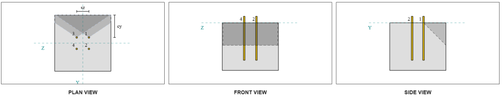
VZ kesme nedeniyle beton kırılma kapasitesini hesaplayın
Taban plakası ayrıca Vz kesme kuvvetine de maruz kalır, yani başarısızlık kenarları Vz kesme kuvvetine dik ve paralel kontrol edilmeli. Aynı yaklaşımı kullanmak, dikey ve paralel kapasiteler şu şekilde hesaplanır: 16.6 Kn ve 37.3 kN, sırasıyla.
Dik Kenar:
Paralel Kenar:
Bu kapasiteler daha sonra gerekli güçlerle karşılaştırılır..
- İçin dik kenar arıza, dan beri 5 kN < 16.6 kN, çarpanlara ayrılmış beton kesme koparma kapasitesi yeterli.
- İçin paralel kenar arızası, dan beri 5 kN < 37.3 kN, çarpanlara ayrılmış beton kesme koparma kapasitesi yeterli.
Soğuk şekillendirilmiş elemanlar aşağıdakilere uygun olarak tasarlanırken #4: Beton Pryout kapasitesini hesaplayın
Beton koni çıkarma hatası kullanılan koninin aynısıdır çekme kopma kontrolü. Kesme kaldırma kapasitesini hesaplamak için, NS nominal çekme kopma mukavemeti İlk önce tekli çapaların veya çapa grubunun sayısı belirlenmelidir. Çekme kopma kontrolü için ayrıntılı hesaplamalar zaten bu bölümde ele alınmıştır. Gerilme Yükü için SkyCiv Tasarım Örnekleri ve burada tekrar edilmeyecektir.
Kaymayla koparma için ankraj grubu belirlemesinin, kesmeyle koparma için belirlenenden farklı olduğuna dikkat etmek önemlidir.. Tasarımdaki ankrajların yine de kontrol edilip edilmediği kontrol edilmelidir. grup olarak veya tek dayanak noktası olarak hareket etmek. sınıflandırması dar bir bölüm olarak destek ayrıca doğrulanmalı ve gerilimin kırılması için kullanılan koşulların aynılarına uyulmalıdır.
SkyCiv yazılımına göre, ankraj grubunun nominal kopma kopma mukavemeti 60.207 kN. Bir gözetleme faktörü ile 2.0, NS faktörlü kaldırma kapasitesi dır-dir:
\( V_{brgr} = c times A_{cp}N_{CBR} = 2 \çarpı 60,207,text{kN} = 120,41,metin{kN} \)
Gerekli güç, sonuç uygulanan kesme yüklerinin. Tüm çapalar tek bir gruba ait olduğundan, toplam bileşke kesme kuvveti gruba atanır.
\( V_{FA} = sqrt{((V_y)^ 2) + ((V_Z)^ 2)} = sqrt{((5\,\Metin{kN})^ 2) + ((5\,\Metin{kN})^ 2)} = 7,0711,metin{kN} \)
\( V_{FA} = sol(\çatlamak{V_{FA}}{yok}\sağ)N_{a,G1} = sol(\çatlamak{7.0711\,\Metin{kN}}{4}\sağ) \zamanlar 4 = 7,0711,metin{kN} \)
Dan beri 7.07 kN < 120.4 kN, çarpanlara ayrılmış kaldırma kapasitesi yeterli.
Soğuk şekillendirilmiş elemanlar aşağıdakilere uygun olarak tasarlanırken #5: Ankraj çubuğu kesme kapasitesini hesaplayın
Bu tasarım örneğinde bunu hatırlayın, kesme kuvveti tüm ankrajlara dağıtılır. NS ankraj başına toplam kesme yükü dolayısıyla Vy yükündeki payının ve Vz yükündeki payının sonucudur. Ayrıca şunları da dikkate alıyoruz: idari dava kesme kopma kontrollerinde kullanılır.
Vy kesme için, Durum 3 yönetiyor.
\( V_{FA,Y} = frac{V_y}{N_{ile,G1}} = frac{5\,\Metin{kN}}{2} = 2,5,metin{kN} \)
benzer şekilde, Vz kesme için, Durum 3 yönetiyor.
\( V_{FA,ile} = frac{V_Z}{N_{Y,G1}} = frac{5\,\Metin{kN}}{2} = 2,5,metin{kN} \)
Bu verir ankraj çubuğu üzerindeki kesme kuvveti gibi:
\( V_{FA} = sqrt{((V_{FA,Y})^ 2) + ((V_{FA,ile})^ 2)} = sqrt{((2.5\,\Metin{kN})^ 2) + ((2.5\,\Metin{kN})^ 2)} = 3,5355,metin{kN} \)
Bu tasarım örneğinde, harç mevcut. Bu nedenle, çapa çubuğu da deneyimliyor eksantrik kesme nedeniyle bükülme. Bunun hesabını vermek, biz de uygulayabiliriz CSA A23.3'e göre harç azaltma faktörü:19 Madde D.7.1.3 veya CSA S16'yı kullanarak kesme-bükme etkileşimini kontrol edin:19 Madde 13.12.1.4.
Bu hesaplama için, kullanmayı tercih ettik 0.8 kesinti CSA A23.3 faktörü. Bireysel mühendislik kararına izin vermek, NS SkyCiv Taban Plakası yazılımı bu azaltma faktörünü devre dışı bırakma ve bunun yerine kesme-bükme etkileşimi kontrolünü kullanma seçeneğini sunar. Bu özellik kullanılarak keşfedilebilir. Taban Plakası Ücretsiz Aracı.
CSA A23.3 Ankraj Çubuğu Kesme Kapasitesi:
İlk, Ankraj çubuğu kesme kapasitesini CSA A23.3'ü kullanarak hesaplıyoruz. NS minimum çekme gerilimi çapa çubuğunun:
\( f_{uta} = min(F_{u _anc}, 1.9F_{ilk}, 860) = min(400\,\Metin{MPa}, 1.9 \çarpı 248,2,text{MPa}, 860.00\,\Metin{MPa}) = 400,metin{MPa} \)
NS faktörlü ankraj çubuğu kesme kapasitesi, kullanılarak hesaplandı CSA A23.3:19 Denklem D.31 ve Madde D.7.1.3, dır-dir:
\( V_{SAR,a23} = 0,8A_{biliyorum,V }\phi_s0.6f_{uta}R = 0.8 \çarpı 92,text{mm}^2 Times 0.85 \zamanlar 0.6 \çarpı 400,text{MPa} \zamanlar 0.75 = 11.258,metin{kN} \)
Şunu unutmayın: 0.8 Harcın varlığı nedeniyle burada azaltma faktörü uygulanır. Bu azaltılmış kesme kapasitesi, ankraj çubuğundaki ek bükülmeyi hesaba katar.
CSA S16 Ankraj Çubuğu Kesme Kapasitesi:
CSA S16 kapasitesi için, sadece kesme kapasitesi kontrol edilird, eksantrik kesmeden kaynaklanan bükülme CSA A23.3 kontrolünde zaten hesaba katıldığından.
NS faktörlü kesme kapasitesi kullanılarak hesaplanır CSA S16:19 Madde 25.3.3.3.
\( V_{r,s16} = 0,7phi_m 0,6n A_{efendim} F_{u _anc} = 0.7 \zamanlar 0.67 \zamanlar 0.6 \zamanlar 1 \çarpı 126,68,text{mm}^2 time 400,text{MPa} = 14.255,metin{kN} \)
Her iki yöntemin de dikkate alındığından emin olmak için, Yönetim kapasitesi iki değerden küçük olanı olarak alınır, hangisi 11.258 kN.
Dan beri 3.54 kN < 11.258 kN, çarpanlara ayrılmış ankraj çubuğu kesme kapasitesi yeterli.
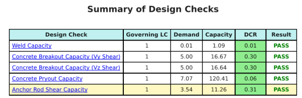
Tasarım Özeti
NS Skyciv Base Plaka Tasarım Yazılımı Bu tasarım örneği için otomatik olarak adım adım hesaplama raporu oluşturabilir. Ayrıca gerçekleştirilen kontrollerin ve bunların sonuç oranlarının bir özetini sağlar, Bir bakışta bilginin anlaşılmasını kolaylaştırmak. Aşağıda bir örnek özet tablosu var, rapora dahildir.
Skyciv Örnek Raporu
SkyCiv Taban Plakası Tasarım Raporundan bekleyebileceğiniz ayrıntı ve netlik düzeyini görün. Rapor tüm önemli tasarım kontrollerini içerir, denklemler, ve sonuçların net ve okunması kolay bir formatta sunulması. Tasarım standartlarıyla tam uyumludur. SkyCiv Taban Plakası Hesaplayıcısı kullanılarak oluşturulan örnek raporu görüntülemek için aşağıya tıklayın.
Base Plaka Yazılımı Satın Alın
Base Plaka Tasarım Modülünün tam sürümünü başka bir SkyCiv modül olmadan kendi başına satın alın. Bu size taban plakası tasarımı için tam bir dizi sonuç verir, ayrıntılı raporlar ve daha fazla işlevsellik dahil.