Bu makalede, saha konumunun rüzgâra karşı tarafının arazisini veya maruz kalma kategorilerini nasıl belirleyeceğiniz konusunda size yol göstereceğiz, Rüzgar yüklerinin hesaplanması için gerekli olan. ASCE'de özetlenen spesifik prosedürleri ele alacağız 7, NBCC 2015, ve AS / NZS 1170.2 Arazi kategorilerini belirlemek ve bunların SkyCiv Yük Oluşturucu'da bulunan her bir referans koduna nasıl uygulanacağını tartışmak için.
ASCE 7-16/ASCE 7-22
ASCE için 7, Bir saha konumunun rüzgara karşı maruziyetinin Maruziyet Kategorisini belirleme prosedürü Bölüm'de tartışılmaktadır. 26.7, araziye bağlı olarak. Bu makalede, referansı basitleştirmek için, ASCE kullanacağız 7-16. Her rüzgar kaynağı yönü için, ±45° uzanan rüzgara karşı iki sektörden analiz edilmelidir.
Figür 1. Her rüzgar kaynağı yönü için arazi sektörleri.
Her sektör için, Yüzey Pürüzlülüğü kategorisi Bölüm bazında aşağıdaki tanıma göre kontrol edilmelidir. 26.7.2 ASCE'nin 7-16:
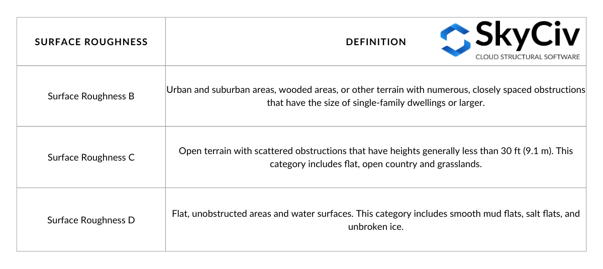
Tablo 1. Kesit bazında Yüzey Pürüzlülüğü tanımı 26.7.2 ASCE'nin 7-16.
Yüzey Pürüzlülüğü tanımından, Rüzgara karşı sektör tarafından sınırlanan arazinin Maruziyet Kategorisini belirleyebiliriz. Her Maruz Kalma Kategorisinin tanımı Bölümde belirtilmiştir. 26.7.3 ASCE'nin 7-16 aşağıdaki gibi:
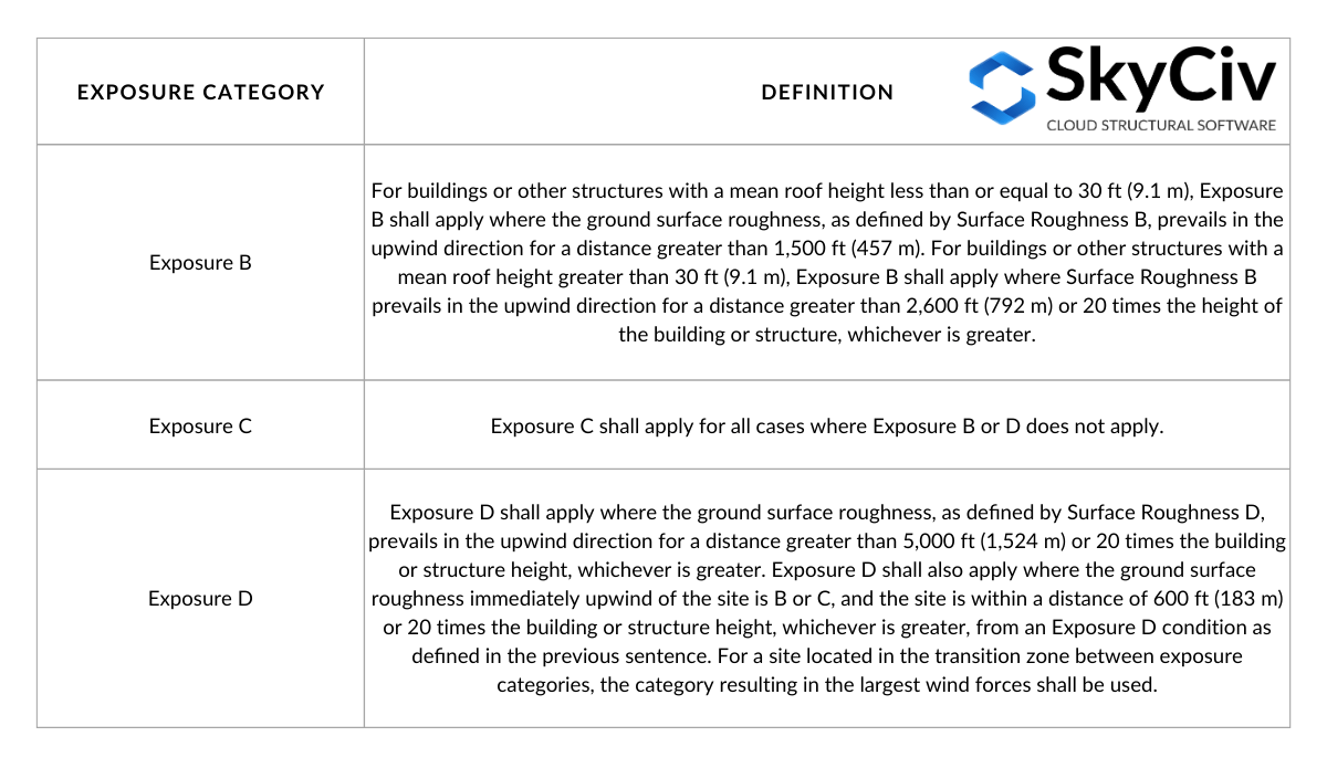
Tablo 2. Bölüme dayalı Maruz Kalma Kategorisi tanımı 26.7.3 ASCE'nin 7-16.
Masa 2 Şekil C26.7-2'ye dayalı olarak aşağıdaki şekillerde görselleştirilebilir:
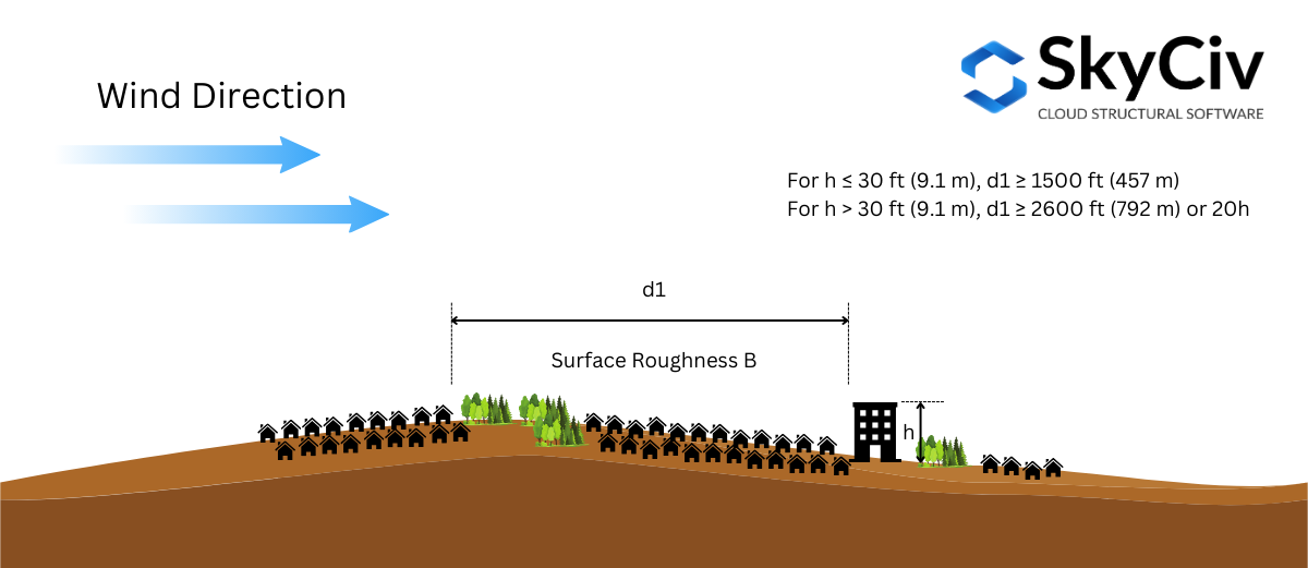
Figür 2. Rüzgara Karşı Yüzey Pürüzlülüğü koşulları Pozlama B için gereklidir.
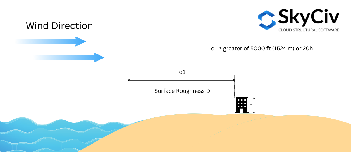
Figür 3. Rüzgara Karşı Yüzey Pürüzlülüğü koşulu, Pozlama D için gereklidir – durum 1.
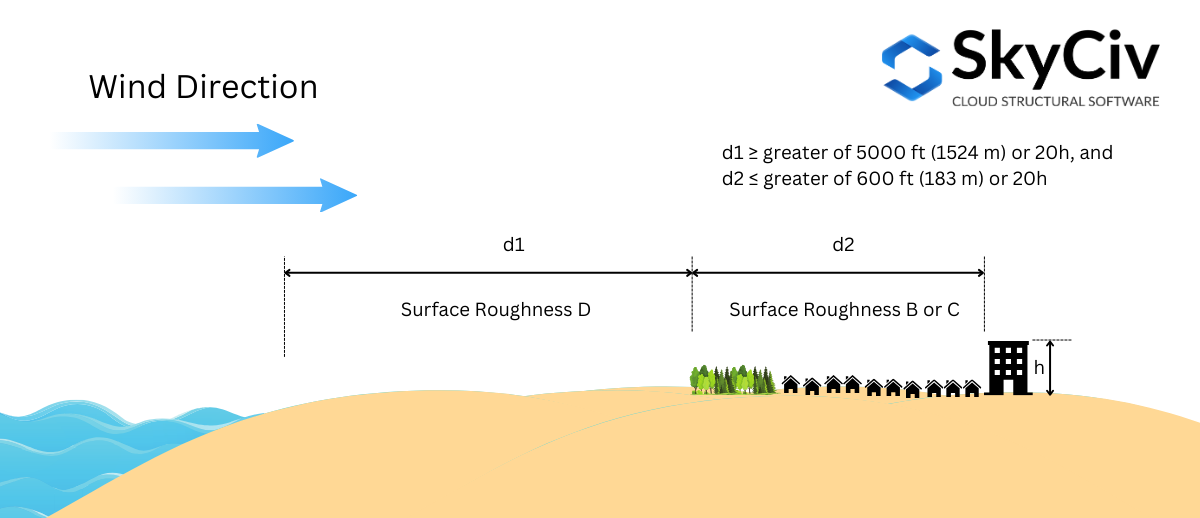
Figür 4. Rüzgara Karşı Yüzey Pürüzlülüğü koşulu, Pozlama D için gereklidir – durum 2.
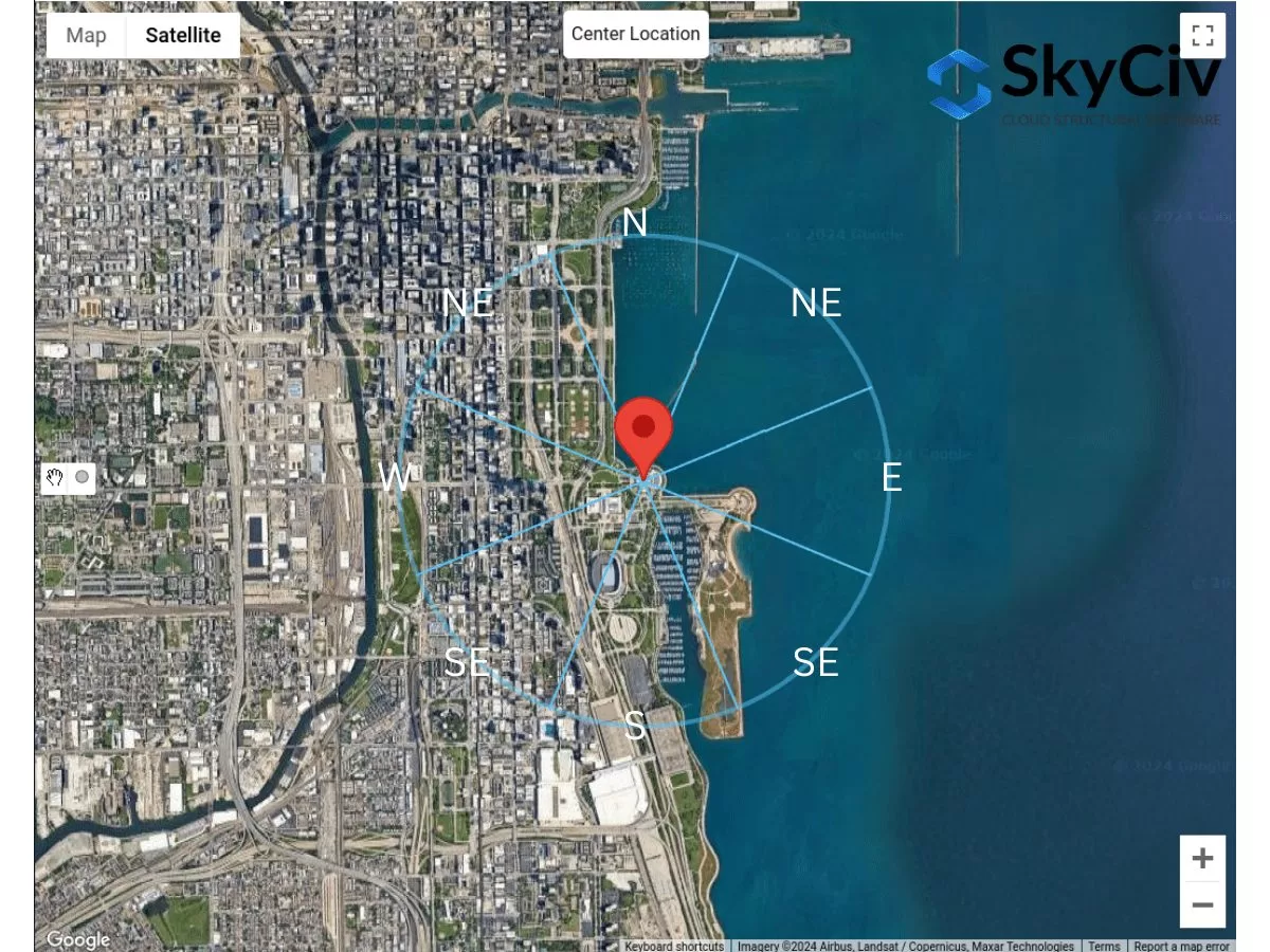
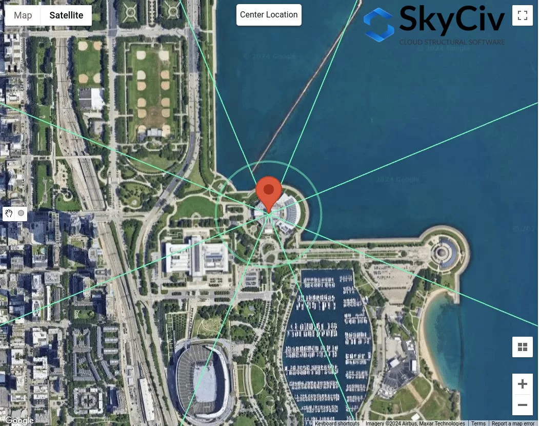
Maruz Kalma Kategorisi her rüzgar kaynağı yönü için belirlenecektir.. Örnek site konumu kullanma – “1200 S DuSable Göl Kıyısı Dr., Chicago, THE 60605, Amerika Birleşik Devletleri”, bunu her yön için analiz edelim.
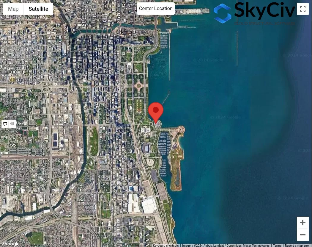
Figür 4. Maruz Kalma Kategorisi analizi için örnek konum.
Yapının ortalama çatı yüksekliğinin 25 ft ( \( 20h = 500 ft \)), her sektör için Maruz Kalma Kategorisini kontrol etmek için aşağıdaki prosedürü kullanacağız:
Durum 1. Şekil'i kullanarak Pozlama D'nin olup olmadığını belirleyin 3:
Şekil Kullanımı 3 – mesafe nerede \( d_{1} \) dır-dir 5000 ft (1524 m), Pozlama D'yi kontrol etmemiz gerekiyor, Yüzey Pürüzlülüğü D'nin bütünü için baskın olduğu yer 5000 ft streç:
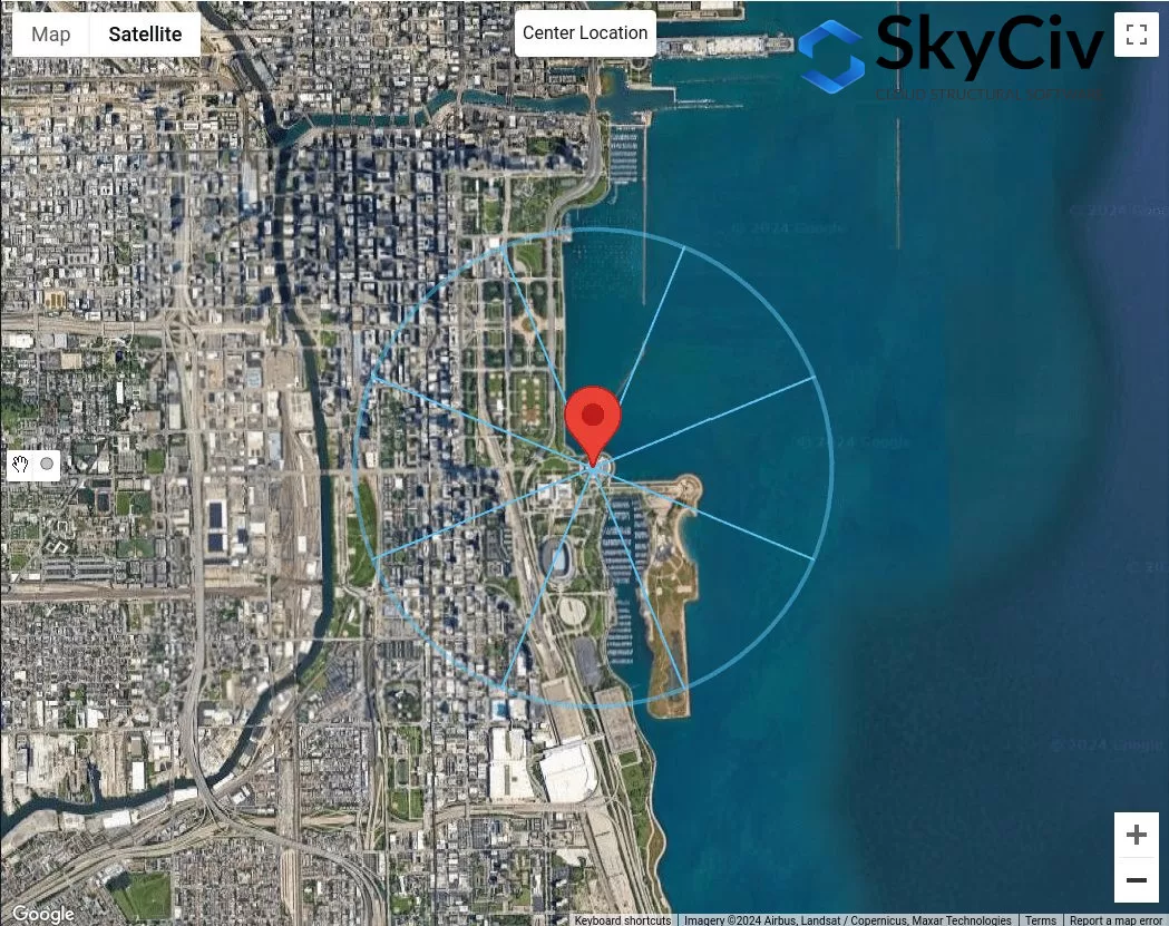
Figür 5. Ofset mesafesi 5000 Şekil kullanarak Pozlama D kontrolü için saha konumundan ft uzakta 3.
Şekilden 5, zaten rüzgar kaynağı yönlerinin olduğu sonucuna varabiliriz N, DOĞDU, ve E tamamı için Yüzey Pürüzlülüğü D'ye sahip olun 5000 ft streç. Bu nedenle, bu rüzgar kaynağı yönleri Pozlama D.
Durum 2. Şekil'i kullanarak Pozlama D'nin olup olmadığını belirleyin 2
Şekil Kullanımı 4 – mesafe nerede \( d_{1} \) dır-dir 5000 ft (1524 m) ve mesafe \( d_{2} \) eşittir 600 ft (183 m), Pozlama D'yi kontrol etmemiz gerekiyor. Şekilden 5, bu yalnızca SE'den gelen rüzgar kaynağı yönü için uygulanabilir:
Figür 6. 600ft ofset mesafesi ve ek 5000 Şekil kullanarak Pozlama D kontrolü için saha konumundan ft uzakta 4.
Rüzgar kaynağı yönü SE için, kullanma \( d_{2} = 600 ft \), bu bölümün Yüzey Pürüzlülüğü B olduğunu düşünebiliriz. ancak, mesafe için \( d_{1} = 5000 ft \), bölüm değil 100% Yüzey Pürüzlülüğü D. Bu nedenle, SE, Pozlama D olarak değerlendirilmemelidir.
Durum 3. Şekil'i kullanarak Pozlama B'nin olup olmadığını belirleyin 1
Şekil Kullanımı 3 – mesafe nerede \( d_{1} \) dır-dir 1500 ft (457 m) dan beri \( h < 30 ft \), Pozlama B'yi kontrol etmemiz gerekiyor.
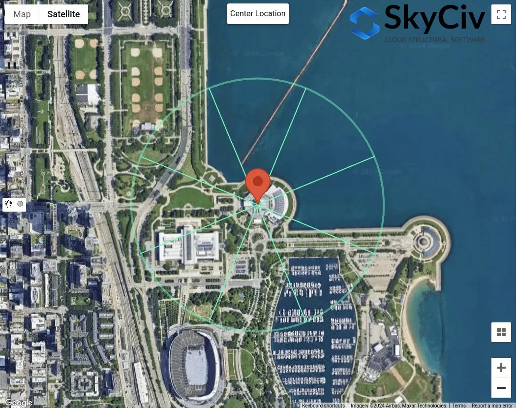
Figür 7. Ofset mesafesi 1500 Şekil kullanarak Pozlama B kontrolü için saha konumundan ft uzakta 3.
Şekilden 7, rüzgar kaynağı yönleri için NW'yi belirleyebiliriz, W, GB, ve S, her yön sektörü için yüzey pürüzlülüğü Yüzey Pürüzlülüğü B olduğundan Pozlama B olarak sınıflandırılır.
Durum 4. Eğer koşullar 1 -e 3 doğru değil, bu nedenle, arazi Pozlama C'dir.
Bu nedenle, rüzgar kaynağı yönü SE için, Maruz Kalma Kategorisi C olarak sınıflandırılmıştır. Özetle, her rüzgar kaynağı yönü için maruz kalma kategorileri Şekilde gösterilmektedir 8 altında.
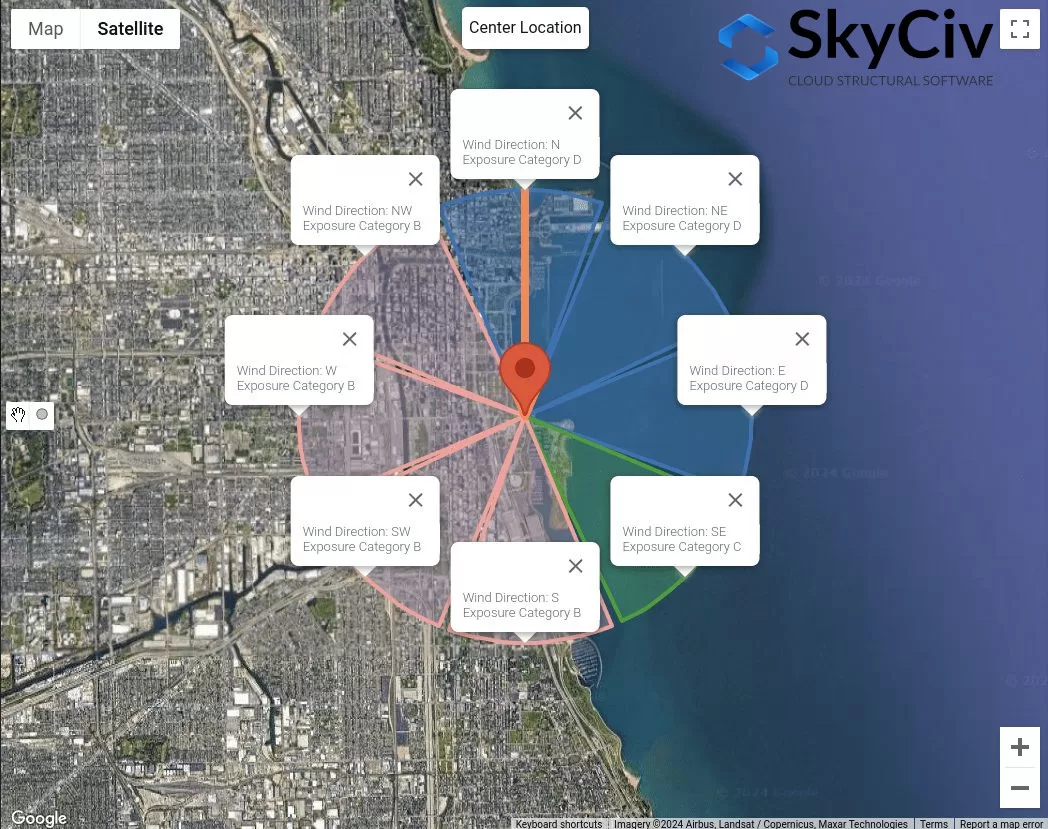
Figür 8. Her rüzgar kaynağı yönü için maruz kalma kategorileri.
Bu veriler, Hız Basınç Katsayıları olarak en kötü rüzgar kaynağı yönünün ne olacağını belirlemek için kullanılabilir. \( k_{ile} \), Topografik Faktör \( k_{t} \), ve Rüzgar Etkisi Faktörü \( G \) ayrıntılı hesaplamanın kullanılması Maruz Kalma Kategorisinden etkilenir.
NBCC 2015/2020
NBCC için 2015, Bir saha konumunun rüzgara karşı maruziyetinin Maruziyet Kategorisini belirleme prosedürü Bölüm'de tartışılmaktadır. 4.1.7.3(5), araziye bağlı olarak. Her rüzgar kaynağı yönü için, ±45° uzanan rüzgara karşı iki sektörden analiz edilmelidir.
Figür 9. Her rüzgar kaynağı yönü için arazi sektörleri.
Her sektör için, Arazi kategorisi Bölüme göre aşağıdaki tanıma göre kontrol edilmelidir. 4.1.7.3(5) NBCC'nin 2015:
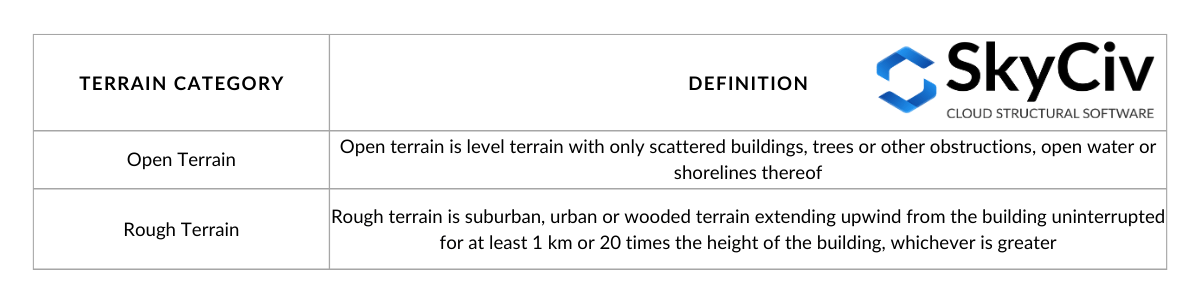
Tablo 3. Bölümde tanımlandığı şekliyle arazi kategorilerinin tanımı 4.1.7.3(5) NBCC'nin 2015.
Tablodaki seçenekleri görselleştirme 3:
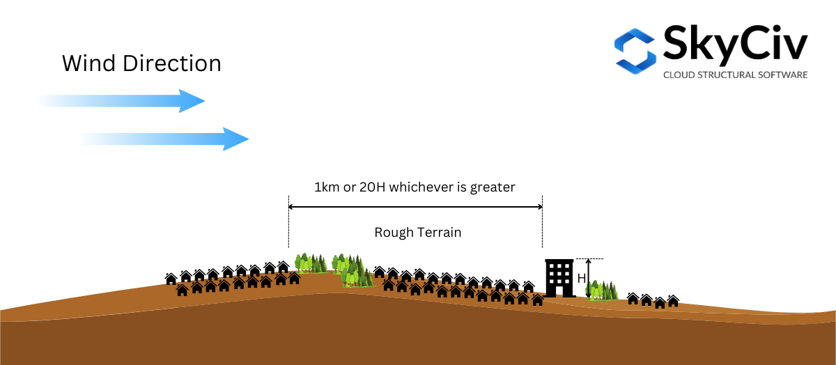
Figür 10. Bölümde Tanımlandığı Şekilde Engebeli Arazinin Tanımı 4.1.7.3(5) NBCC'nin 2015.
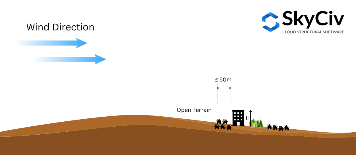
Figür 10. Bölümde tanımlandığı şekliyle Açık Arazinin Tanımı 4.1.7.3(5) NBCC'nin 2015.
Bölüm bazında 4.1.7.3(5) NBCC'nin 2015, enterpolasyon yapılmasına izin verilir Maruziyet Faktörü \( C_{e} \) orta arazide. Yapının bulunduğu yerden engebeli arazi mesafesi 1km veya daha fazla ise veya 20 yapı yüksekliğinin katı, Hangisi daha iyiyse, arazi olarak düşünülebilir Engebeli Arazi, ve eğer mesafe daha azsa 50 m, olarak kabul edilir Açık Arazi. Aksi takdirde, Maruz Kalma Faktörü \( C_{e} \) form, belirli bir tasarım elemanını analiz etmek için kullanılacak tüm parametreleri içerir. 4.1.7.3(5) sınır değerlerinden hesaplanacaktır. Bu Şekilde görselleştirilebilir 11 altında.
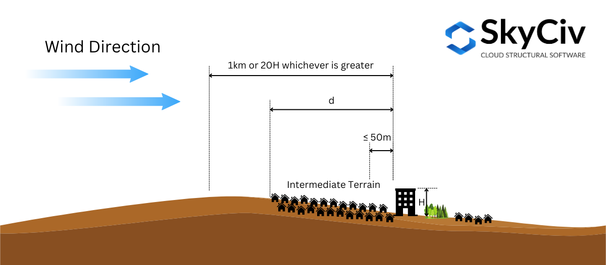
Figür 11. Bölümde tanımlandığı şekliyle Ara Arazinin Tanımı 4.1.7.3(5) NBCC'nin 2015.
Bunu daha da açıklamak gerekirse, örnek bir site konumu kullanalım – “657 Ustalar Rd SE, NBCC'nin tamamen işlenmiş bir örneği, AB T3M 2B6, Kanada,” yapının yüksekliğini varsayarsak \( H \) dır-dir 25 m ( \( 20H = 500 m \)).
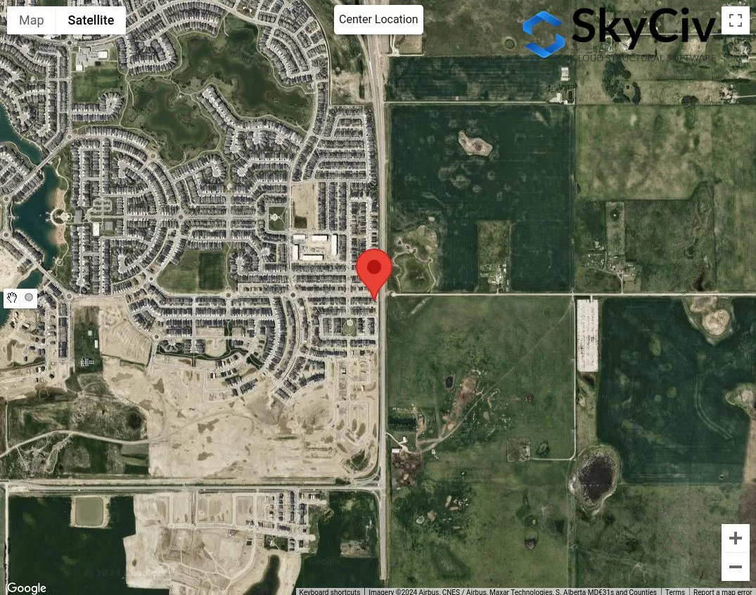
Figür 12. Arazi Kategorisi analizi için örnek konum.
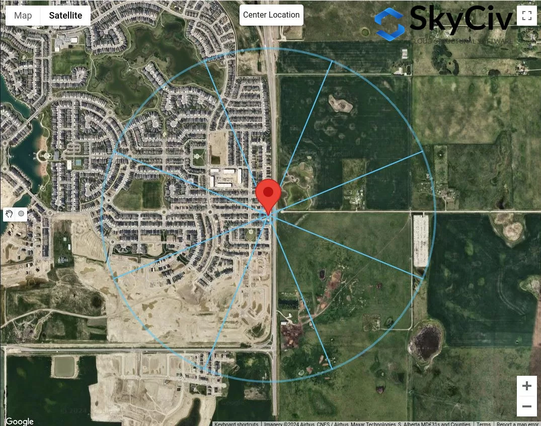
İlk adım, her rüzgar kaynağı yönü için belirgin engebeli ve açık arazi kategorilerini sınıflandırmaktır.. 50m ve maksimum çizebiliriz 1 km veya \( 20 H \) site konumundan yarıçap.
Figür 13. Tabloya göre arazi kategorisinin belirlenmesi için 50 m ve 1 km ofset mesafesi 1 tanımlar.
Şekilden 13, rüzgar kaynağı yönlerini söyleyebiliriz DOĞDU, E, ve SE olarak sınıflandırılır Açık arazi her yön için engebeli arazi uzunluğu saha konumundan 50 m'den az olduğundan. Dahası, rüzgar kaynağı yönleri için Batı ve Kuzeybatı Bu yönler için engebeli arazi uzunluğu, engebeli araziden daha büyük olduğundan Engebeli Arazi olarak sınıflandırılabilir. 1 km. Rüzgar kaynağı yönü için N, ihtiyatlı bir şekilde Açık Arazinin bu yönde baskın olduğunu varsayabiliriz.. Geri kalanı için, S ve GB, bunların Orta Arazi olduğu sonucuna varabiliriz ve engebeli arazinin saha konumuna olan mesafesini ölçmemiz gerekecek.
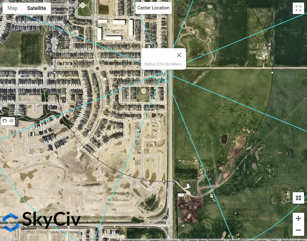
Figür 14. SW rüzgar kaynağı yönü için saha konumundan ölçülen yaklaşık engebeli arazi uzunluğu şuna eşittir: 574 m.
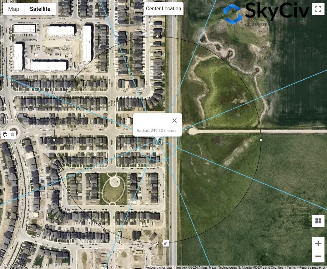
Figür 15. S rüzgar kaynağı yönü için saha konumundan ölçülen yaklaşık engebeli arazi uzunluğu şuna eşittir: 249 m.
Yukarıdaki analizden, kesinlikle Açık Arazi ile rüzgar kaynağı yönleri kesinlikle muhafazakar değerleri verecektir. ancak, tüm rüzgar kaynağı yönleri Orta Arazi olarak sınıflandırılmışsa, Yukarıdaki prosedür, her yön için uygun Arazi Kategorisini nasıl belirleyeceğinizi gösterir..
AS / NZS 1170.2 (2021)
AS / NZS için 1170.2, Yukarıdaki referanslarla aynı prosedür, bir saha konumunun rüzgara karşı maruziyetinin Arazi Kategorisinin belirlenmesinde de geçerlidir.. Bu, Bölüm'de tartışılmaktadır. 4.2 AS / NZS 1170.2 (2021). Her rüzgar kaynağı yönü için, ±45° uzanan rüzgara karşı iki sektörden analiz edilmelidir. Her arazi kategorisinin tanımı Bölüme göre aşağıda gösterilmektedir. 4.2.1 AS / NZS 1170.2 (2021):
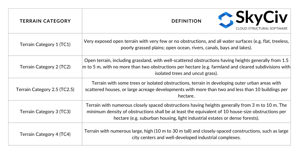
Tablo 4. Bölümde tanımlandığı şekliyle arazi kategorilerinin tanımı 4.2.1 AS / NZS 1170.2 (2021).
Bir yön için arazi kategorisinin belirlenmesinde, eşit bir gecikme mesafesi \( 20 ile \) yapının konumundan ihmal edilecektir. tüm W10 boyutlu bölümleri ve W12x14 boyutlu bölümleri hariç tutacaktır, ofset mesafesi (ortalama mesafe) nın-nin 500 m veya \( 40 z), hangisi daha büyükse, Şekilde gösterildiği gibi kullanılacaktır 16 altında. NS \( ile \) değer ortalama çatı yüksekliğine eşittir, \( h \), küçük veya eşit olduğunda 25 m. Bu ortalama mesafe içerisinde birden fazla arazi kategorisinin bulunması mümkündür., ve bu şekilde, belirlenmesinde doğrusal enterpolasyon kullanılacaktır. \( M_{ile,kedi} \) değerler, her arazi kategorisinin uzunluğuna bağlı olarak, Şekilde gösterildiği gibi 4.1 AS / NZS 1170.2 (2021). Bu makalede, ortalama mesafe dahilinde yalnızca homojen bir arazi kategorisini dikkate alacağız.
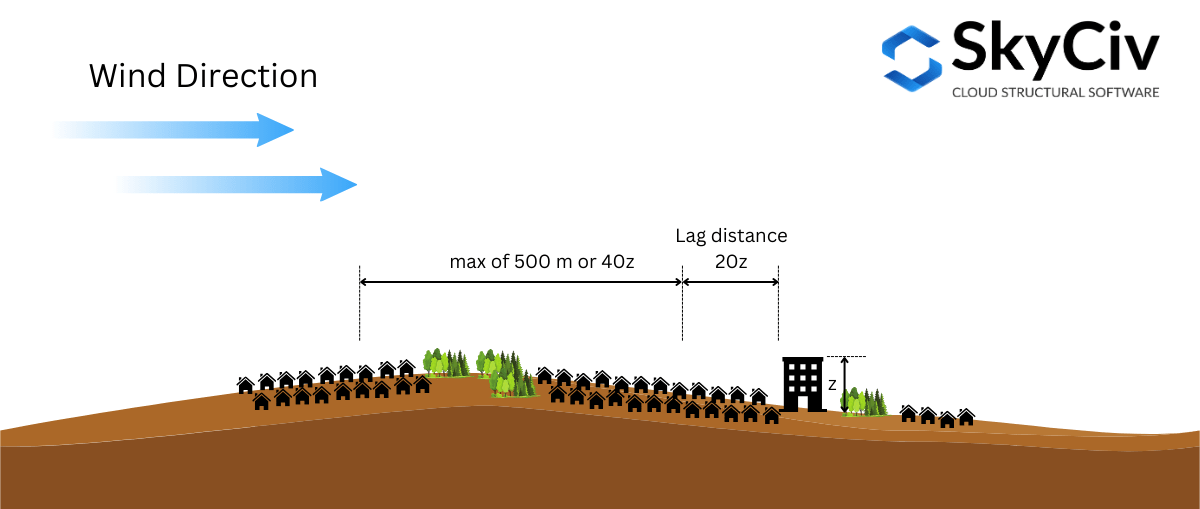
Figür 16. AS/NZS'ye göre Arazi Kategorisinin belirlenmesinde kullanılan mesafelerin gösterimi 1170.2 (2021).
Bunu daha da açıklamak gerekirse, örnek bir site konumu kullanalım – Enlem: 32°43’46″S Uzun: 151°31’47″E – ortalama çatı yüksekliğini varsayarsak \( h \) dır-dir 10 m ( nerede \( 20z = 20 saat = 200 m \) ve \( 40z = 400 m \)).
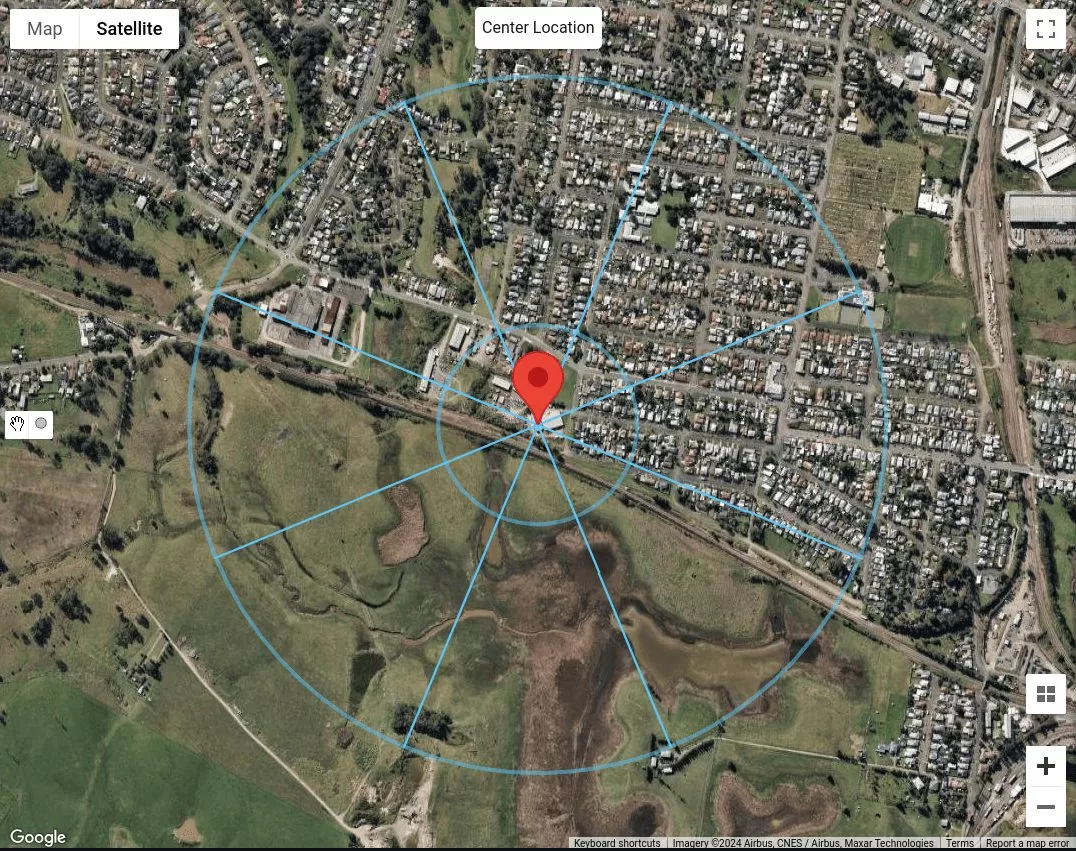
Figür 17. Gecikme mesafesi eşit olan site konumu 200 m ve ortalama mesafe eşittir 500 her rüzgar kaynağı yönü için m.
Arazi kategorisini yalnızca 500 m'nin tamamı boyunca homojen olarak kabul edeceğimiz için veya \( 40ile \) Üst ve alt çatının boşluğunu ve farkını gösteren yükseklik görünümü, zaten her rüzgar kaynağı yönünü sınıflandırabiliriz. N üzerindeki binaları varsayarsak, NE ve E, binalar öyle mi 5 -e 10 m boyunda, bunları Arazi Kategorisine göre sınıflandırabiliriz 3 (TC3) Tabloda gösterildiği gibi 4. Rüzgar kaynağı yönleri için SE, S, GB, ve W, çünkü bunlar engelsiz çimenlik düzlükler, bunları Arazi Kategorisi olarak sınıflandırabiliriz 1 (TC1). En sonunda, Rüzgar kaynağı yönü Kuzeybatı için, ikiden fazla ama daha az olduğu sonucunu çıkarabiliriz 10 hektar başına bina, dağınık evlerle. Bu nedenle, bunu Arazi Kategorisi olarak sınıflandırabiliriz 2.5 (TC2.5).
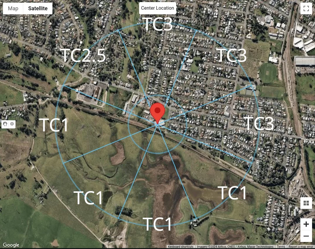
Figür 18. Örnek konumumuz için her bir rüzgar kaynağı yönü için arazi kategorisi sınıflandırmasının özeti.
SkyCiv Yük Oluşturucuyu Kullanma
SkyCiv Load Generator v4.7.0 sürümünde, yeni harita araçları tanıtıldı – Mesafeyi Ölç ve Mesafe Yarıçapları aletler.
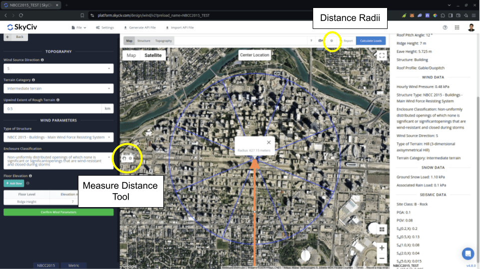
Figür 19. SkyCiv Load Generator'a eklenen mesafe ölçüm araçları.
NS Mesafeyi Ölç Araç, haritada tıklanan bir noktadan bir daire oluşturmak ve yarıçapını metre cinsinden göstermek için kullanılır.. Bu yoldan, belirli konumlarda analiz edilen konuma olan mesafeleri ölçebilirsiniz. Bu, NBCC'de ölçüm yaparken kullanılabilir 2015 için Engebeli Arazinin Rüzgara Karşı Boyutu hesaplamada kullanılır Maruziyet Faktörü \( C_{e} \). Oluşturulan daireye tıklamak onu haritadan temizleyecektir.
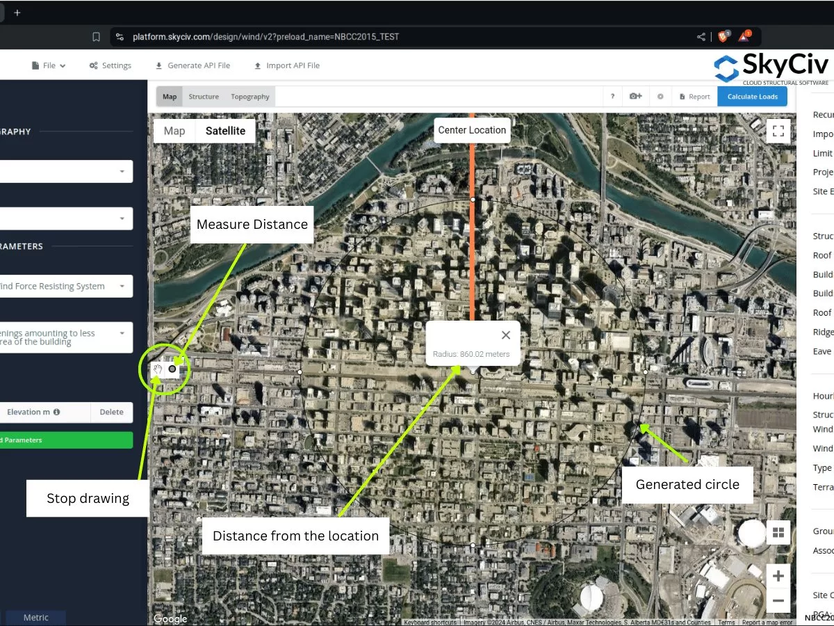
Figür 20. SkyCiv Load Generator'a sunulan, konumdan bir uzaklık oluşturan ve merkezden yarıçapı/ofset mesafesini gösteren mesafeyi ölçme aracı.
Diğer taraftan, NS Mesafe Yarıçapları kullanıcıların her rüzgar kaynağı kategorisi için konumdan belirli mesafelerde daireler çizebilmesi için tanıtıldı. Haritadaki mesafe yarıçaplarını göstermek veya gizlemek için bir geçiş düğmesidir, Site konumu dairelerin merkezi olacak şekilde.
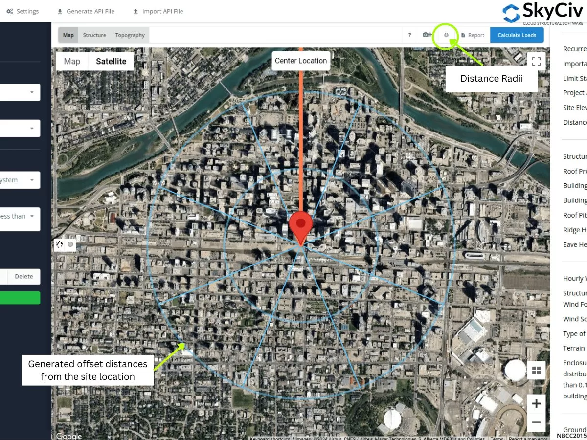
Figür 21. SkyCiv Load Generator'a sunulan saha konumundan ofset mesafelerini belirten Mesafe Yarıçapı aracı.
Yarıçap değerleri Ayarlar'ın açılmasıyla düzenlenebilir.
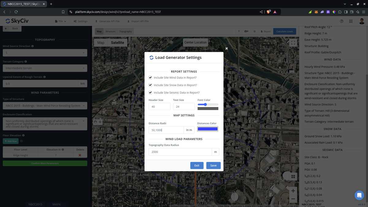
Figür 22. SkyCiv Load Generator'da Mesafe Yarıçapı aracı için mesafeleri düzenlemeye yönelik ayarlardaki seçenek.
Yazılım tarafından otomatik olarak hesaplanmadığından kullanıcıların mesafe değerlerini düzenlemesi gerektiğini unutmayın.. Bunu ASCE için kullanma 7 ve NBCC, Her rüzgar kaynağı yönü için en kötü maruziyet veya arazi kategorisi benimsenecektir.. AS/NZS'de kullanılmasıyla ilgili olarak 1170.2 (2021), yazılım ortalamayı hesaplamak için yarıçap değerlerini kullanmaz \( M_{ile,kedi} \) değerler. Yerine, ortalama mesafe, homojen bir Arazi Kategorisi atayabileceğimiz uygulanabilir aralık olarak kullanılır, Her rüzgar kaynağı yönü için en kötü kategoriyi benimsemek.
Yukarıda tartışılan bölümlerden, Her bir rüzgar kaynağı yönü için maruz kalma veya arazi kategorilerini belirlemek amacıyla bu yeni araçları kullanabilirsiniz.. Yukarıdaki prosedürler size her rüzgar kaynağı yönünün hızlı bir arazi sınıflandırmasını verebilir.. CBS ve yapay zeka araçlarını kullanma, Yukarıda kullandığımız kriterleri her bir rüzgar kaynağı yönü için ayrıca kontrol edebilir ve daha iyi ve verimli bir sonuç elde edebilirsiniz..

Yapı mühendisi, Ürün geliştirme
Yüksek Lisans İnşaat Mühendisliği
Referanslar:
- Binalar ve Diğer Yapılar için Minimum Tasarım Yükleri. (2017). EKSENLER / ALTI 7-16. Amerikan İnşaat Mühendisleri Derneği.
- kar yükleme-örnek-nbcc2015-ekran görüntüsü-25. (2015). NBCC'nin tamamen işlenmiş bir örneği, 2015. kar yükleme-örnek-nbcc2015-ekran görüntüsü-25.
- Standartlar Avustralya (2021), Yapısal Tasarım Eylemleri. Bölüm 2 Avustralya ve Yeni Zelanda'da, Avustralya/Yeni Zelanda Standardı AS/NZS1170.2:2021, Standartlar Avustralya, Sydney, NSW, Avustralya.
- Google Maps