Пример дизайна базовой плиты с использованием en 1993-1-8:2005, В 1993-1-1:2005, В 1992-1-1:2004, и EN 1992-4:2018.
Запись о проблеме
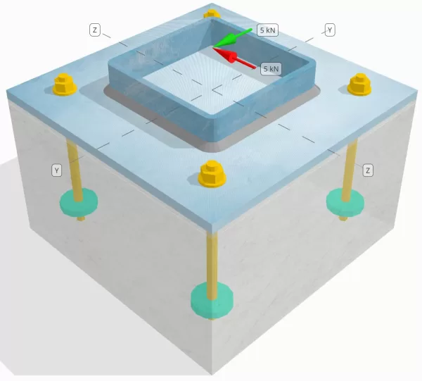
Определите, достаточно ли разработанного соединения с столбцами-базой для Вы = 5-kn и VZ = 5-кн поперечные нагрузки.
Данные данных
Столбец:
Раздел столбца: SHS 180x180x8
Область столбца: 5440 мм2
Материал столбца: S235
Опорная плита:
Размеры опорной плиты: 350 мм х 350 мм
Толщина опорной плиты: 12 мм
Материал опорной плиты: S235
Раствор:
Толщина затирки: 6 мм
Затирной материал: ≥ 30 МПа
бетон:
Бетонные размеры: 350 мм х 350 мм
Бетонная толщина: 350 мм
Бетонный материал: C25/30
Потрескался или не снят: Потрескался
Якоря:
Диаметр якоря: 12 мм
Эффективная длина встраивания: 150 мм
Встроенный диаметр пластины: 60 мм
Встроенная тарелка толщина: 10 мм
Якорный материал: 8.8
Другая информация:
- НЕПРАВИЛЬНЫЕ АКЛАНКИ.
- Якорь с резьбой.
- Коэффициент K7 для якорного сдвига стального сдвига: 1.0
- Степень сдержанности крепежа: Нет сдержанности
Швы:
Сварной шва: Сваркала филе
Сварная нога: 8мм
Классификация металла наполнителя: E35
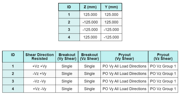
Якоря данных (из Skyciv Calculator):
Модель в бесплатном инструменте SkyCiv
Смоделируйте конструкцию опорной плиты, указанную выше, с помощью нашего бесплатного онлайн-инструмента сегодня.! Регистрация не требуется.
Определения
Путь нагрузки:
В Программное обеспечение SkyCiv для проектирования опорной плиты следует В 1992-4:2018 Для якорного дизайна стержня. Нагрузки на сдвиг, приложенные к колонне, переносятся на опорную плиту через сварные швы, а затем в опорный бетон через якорные стержни. Торы и сдвиговые выкупы не рассматриваются в этом примере, Поскольку эти механизмы не поддерживаются в текущем программном обеспечении.
Якорные группы:
Программное обеспечение включает интуитивно понятную функцию, которая определяет, какие якоря являются частью якоря для оценки Бетонное сдвиг прорыв и Бетонный сдвиг Прайут неудачи.
An Якорная группа определяется как два или более якоря с перекрывающимися областями сопротивления. В таком случае, Якоря действуют вместе, и их комбинированное сопротивление проверяется на приложенной нагрузке на группу.
А Одиночный якорь определяется как якорь, чья проектная область сопротивления не перекрывается с каким -либо другим. В таком случае, Якорь действует в одиночку, и приложенная сила сдвига на этом якоре проверяется непосредственно на его индивидуальное сопротивление.
Это различие позволяет программному обеспечению захватывать как поведение группы, так и индивидуальные характеристики привязки при оценке режимов отказа, связанных с сдвигом.
Пошаговые расчеты
Проверьте #1: Рассчитайте емкость сварки
Мы предполагаем, что ВЗ нагрузку на сдвиг сопротивляется сварные швы с верхней и нижней частью, в то время Vy нагрузка на сдвиг сопротивляется исключительно Левый и правый сварной швы.
Чтобы определить сварную емкость сварные швы с верхней и нижней частью, Сначала мы рассчитываем их Общая длина сварки.
\(
L_{вес,Топ&низ} знак равно 2 \осталось(б_{полковник} – 2т_{полковник} – 2р_{полковник}\право)
знак равно 2 \раз осталось(180 \,\текст{мм} – 2 \раз 8 \,\текст{мм} – 2 \раз 4 \,\текст{мм}\право)
знак равно 312 \,\текст{мм}
\)
следующий, мы рассчитываем стрессы в сварке.
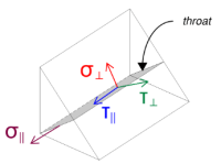
Обратите внимание, что приложенное сдвиг VZ действует параллельно оси сварки, без каких -либо других сил. Это означает, что перпендикулярные напряжения могут быть приняты как ноль, и только стресс сдвига в параллельном направлении необходимо рассчитать.
\(
\сигма_{\преступник} = frac{N}{(L_{вес,Топ&низ})\,A sqrt{2}}
= frac{0 \,\текст{кН}}{(312 \,\текст{мм}) \раз 5.657 \,\текст{мм} \раз sqrt{2}}
знак равно 0
\)
\(
\ваш_{\преступник} = frac{0}{(L_{вес,Топ&низ})\,A sqrt{2}}
= frac{0 \,\текст{кН}}{(312 \,\текст{мм}) \раз 5.657 \,\текст{мм} \раз sqrt{2}}
знак равно 0
\)
\(
\ваш_{\параллельный} = frac{V_{с участием}}{(L_{вес,Топ&низ})\,а }
= frac{5 \,\текст{кН}}{(312 \,\текст{мм}) \раз 5.657 \,\текст{мм}}
знак равно 2.8329 \,\текст{МПа}
\)
С использованием В 1993-1-8:2005, уравнение. 4.1, Проектное напряжение сварного шва получается с использованием метода направления.
\(
F_{вес,Ed1} = кврт{ (\сигма_{\преступник})^ 2 + 3 \осталось( (\ваш_{\преступник})^ 2 + (\ваш_{\параллельный})^2 ПРАВО) }
= кврт{ (0)^ 2 + 3 \раз осталось( (0)^ 2 + (2.8329 \,\текст{МПа})^2 ПРАВО) }
знак равно 4.9067 \,\текст{МПа}
\)
К тому же, Проектирование нормального напряжения для проверки базового металла, в В 1993-1-8:2005, уравнение. 4.1, принимается как ноль, поскольку Нет нормального стресса присутствует.
\(
F_{вес,Ed2} = sigma_{\преступник} знак равно 0
\)
Сейчас же, Давайте оценим Левый и правый сварной швы. Как с верхним и нижним сварным шваром, Сначала мы рассчитываем Общая длина сварного шва.
\(
L_{вес,левый&право} знак равно 2 \осталось(d_{полковник} – 2т_{полковник} – 2р_{полковник}\право)
знак равно 2 \раз осталось(180 \,\текст{мм} – 2 \раз 8 \,\текст{мм} – 2 \раз 4 \,\текст{мм}\право)
знак равно 312 \,\текст{мм}
\)
Затем мы рассчитываем компоненты сварные напряжения.
\(
\сигма_{\преступник} = frac{N}{(L_{вес,левый&право})\,A sqrt{2}}
= frac{0 \,\текст{кН}}{(312 \,\текст{мм}) \раз 5.657 \,\текст{мм} \раз sqrt{2}}
знак равно 0
\)
\(
\ваш_{\преступник} = frac{0}{(L_{вес,левый&право})\,A sqrt{2}}
= frac{0 \,\текст{кН}}{(312 \,\текст{мм}) \раз 5.657 \,\текст{мм} \раз sqrt{2}}
знак равно 0
\)
\(
\ваш_{\параллельный} = frac{V_Y}{(L_{вес,левый&право})\,а }
= frac{5 \,\текст{кН}}{(312 \,\текст{мм}) \раз 5.657 \,\текст{мм}}
знак равно 2.8329 \,\текст{МПа}
\)
С использованием В 1993-1-8:2005, уравнение. 4.1, Мы определяем как конструктивное напряжение сварного шва, так и конструктивное нормальное напряжение для проверки основного металла.
\(
F_{вес,Ed1} = кврт{ \осталось( \сигма_{\преступник} \право)^ 2 + 3 \осталось( \осталось( \ваш_{\преступник} \право)^ 2 + \осталось( \ваш_{\параллельный} \право)^2 ПРАВО) }
\)
\(
F_{вес,Ed1} = кврт{ \осталось( 0 \право)^ 2 + 3 \раз осталось( \осталось( 0 \право)^ 2 + \осталось( 2.8329 \,\текст{МПа} \право)^2 ПРАВО) }
\)
\(
F_{вес,Ed1} знак равно 4.9067 \,\текст{МПа}
\)
Следующим шагом является определение управляющий сварной стресс между сварными швами верхней/нижней и левой/правой сварной швы. Потому что длина сварки равна, а приложенные нагрузки имеют одинаковую величину, полученные сварные напряжения равны.
\(
F_{вес,Ed1} = макс(F_{вес,Ed1}, \, F_{вес,Ed1})
= макс(4.9067 \,\текст{МПа}, \, 4.9067 \,\текст{МПа})
знак равно 4.9067 \,\текст{МПа}
\)
Нагрузки на базовый металл остается нулевым.
\(
F_{вес,Ed2} = макс(F_{вес,Ed2}, \, F_{вес,Ed2}) = макс(0, \, 0) знак равно 0
\)
Сейчас же, Мы рассчитываем емкость сварки. Первый, Сопротивление угловой шов вычисляется. затем, Сопротивление базовый металл определяется. Использование EN 1993-1-8:2005, уравнение. 4.1, способности рассчитываются следующим образом:
\(
F_{вес,Rd1} = frac{f_u}{\Beta_W Left(\гамма_{М2, скоро}\право)}
= frac{360 \,\текст{МПа}}{0.8 \раз (1.25)}
знак равно 360 \,\текст{МПа}
\)
\(
F_{вес,Rd2} = frac{0.9 f_u}{\гамма_{М2, скоро}}
= frac{0.9 \раз 360 \,\текст{МПа}}{1.25}
знак равно 259.2 \,\текст{МПа}
\)
В завершение, Мы сравниваем сварные напряжения с сварными возможностями, и нагрузки на базовый металл с базовыми металлическими способностями.
поскольку 4.9067 МПа < 360 МПа и 0 МПа < 259.2 МПа, емкость сварного соединения достаточный.
Проверьте #2: Рассчитайте бетонную прорывную способность из -за сдвига VY
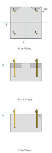
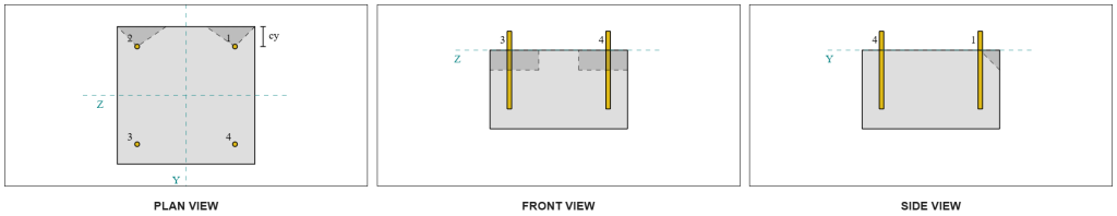
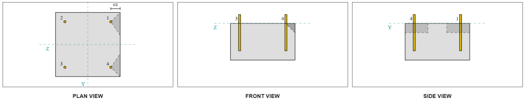
Следуя положениям В 1992-4:2018, Край, перпендикулярный приложенной нагрузке. Только Якоря ближе к этому краю считаются занятыми, Пока предполагается, что оставшиеся якоря не сопротивляются сдвигу.
Эти краевые якоря должны иметь бетонное расстояние больше, чем больше, чем на 10 · HEF и 60 · D, где иметь Длина вложения и d это якорный диаметр. Если это условие не выполнено, Толщина опорной плиты должна быть менее 0,25 · HEF.
Если требования в В 1992-4:2018, Пункт 7.2.2.5(1), не удовлетворены, Программное обеспечение Skyciv не может продолжить проверку дизайна, и пользователю рекомендуется ссылаться на другие соответствующие стандарты.
Из результатов программного обеспечения Skyciv, Крайные якоря действуют как одиночные якоря, Поскольку их прогнозируемые области не перекрываются. Для этого расчета, Якорь 1 будет рассмотрен.
Чтобы вычислить часть нагрузки на сдвиг VY, переносимой якорем 1, Общий сдвиг VY распределяется среди якорей, ближайших к краю. Это дает Перпендикулярная сила на якоре 1.
\(
V_{\преступник} = frac{V_Y}{n_{а ,s}}
= frac{5 \,\текст{кН}}{2}
знак равно 2.5 \,\текст{кН}
\)
Для Параллельная сила, Предполагается, что все якоря одинаково сопротивляются нагрузке. Следовательно, параллельный компонент нагрузки рассчитывается как:
\(
V_{\параллельный} = frac{V_Z.}{n_{anc}}
= frac{5 \,\текст{кН}}{4}
знак равно 1.25 \,\текст{кН}
\)
В Общая нагрузка на сдвиг на якоре 1 поэтому:
\(
V_{издание} = кврт{ \осталось( V_{\преступник} \право)^ 2 + \осталось( V_{\параллельный} \право)^ 2 }
\)
\(
V_{издание} = кврт{ \осталось( 2.5 \,\текст{кН} \право)^ 2 + \осталось( 1.25 \,\текст{кН} \право)^ 2 } знак равно 2.7951 \,\текст{кН}
\)
Первая часть расчета емкости - определить альфа и бета -факторы. Мы используем В 1992-4:2018, Пункт 7.2.2.5, Чтобы установить LF измерение, и Уравнения 7.42 и 7.43 определить факторы.
\(
l_f = min(час_{ef}, \, 12d_{anc})
= min(150 \,\текст{мм}, \, 12 \раз 12 \,\текст{мм})
знак равно 144 \,\текст{мм}
\)
\(
\альфа = 0.1 \осталось(\гидроразрыва{L_F}{c_{1,с1}}\право)^{0.5}
знак равно 0.1 \раз осталось(\гидроразрыва{144 \,\текст{мм}}{50 \,\текст{мм}}\право)^{0.5}
знак равно 0.16971
\)
\(
\бета = 0.1 \осталось(\гидроразрыва{d_{anc}}{c_{1,с1}}\право)^{0.2}
знак равно 0.1 \раз осталось(\гидроразрыва{12 \,\текст{мм}}{50 \,\текст{мм}}\право)^{0.2}
знак равно 0.07517
\)
Следующим шагом является вычисление начальное значение характерного сопротивления крепежа. С использованием В 1992-4:2018, Уравнение 7.41, значение есть:
\(
V^{0}_{Рк,с} = k_9 Left( \гидроразрыва{d_{anc}}{\текст{мм}} \право)^{\альфа}
\осталось( \гидроразрыва{L_F}{\текст{мм}} \право)^{\бета}
\SQRT{ \гидроразрыва{f_{ск}}{\текст{МПа}} }
\осталось( \гидроразрыва{c_{1,с1}}{\текст{мм}} \право)^{1.5} N
\)
\(
V^{0}_{Рк,с} знак равно 1.7 \раз осталось( \гидроразрыва{12 \,\текст{мм}}{1 \,\текст{мм}} \право)^{0.16971}
\раз осталось( \гидроразрыва{144 \,\текст{мм}}{1 \,\текст{мм}} \право)^{0.07517}
\раз sqrt{ \гидроразрыва{20 \,\текст{МПа}}{1 \,\текст{МПа}} }
\раз осталось( \гидроразрыва{50 \,\текст{мм}}{1 \,\текст{мм}} \право)^{1.5}
\раз 0.001 \,\текст{кН}
\)
\(
V^{0}_{Рк,с} знак равно 5.954 \,\текст{кН}
\)
затем, Мы вычисляем Ссылка на прогнозируемая область одного якоря, следующий В 1992-4:2018, Уравнение 7.44.
\(
A_{с,V}^{0} знак равно 4.5 \осталось( c_{1,с1} \право)^ 2
знак равно 4.5 \раз осталось( 50 \,\текст{мм} \право)^ 2
знак равно 11250 \,\текст{мм}^ 2
\)
После того, Мы вычисляем Фактическая прогнозируемая область якоря 1.
\(
B_{с,V} = min(c_{осталось,с1}, \, 1.5c_{1,с1}) + \мин(c_{право,с1}, \, 1.5c_{1,с1})
\)
\(
B_{с,V} = min(300 \,\текст{мм}, \, 1.5 \раз 50 \,\текст{мм}) + \мин(50 \,\текст{мм}, \, 1.5 \раз 50 \,\текст{мм}) знак равно 125 \,\текст{мм}
\)
\(
ЧАС_{с,V} = min(1.5c_{1,с1}, \, т_{концентрация}) = min(1.5 \раз 50 \,\текст{мм}, \, 200 \,\текст{мм}) знак равно 75 \,\текст{мм}
\)
\(
A_{с,V} = Н_{с,V} B_{с,V} знак равно 75 \,\текст{мм} \раз 125 \,\текст{мм} знак равно 9375 \,\текст{мм}^ 2
\)
Нам также необходимо рассчитать параметры для прорыва сдвига. Мы используем В 1992-4:2018, Уравнение 7.4, Чтобы получить фактор, который учитывает нарушение распределения стресса, Уравнение 7.46 Для фактора, который учитывает толщина члена, и Уравнение 7.48 Для фактора, который учитывает Влияние нагрузки на сдвиг, наклоненное к краю. Они рассчитываются следующим образом:
\(
\PSI_{s,V} = min left( 0.7 + 0.3 \осталось( \гидроразрыва{c_{2,с1}}{1.5c_{1,с1}} \право), \, 1.0 \право)
= min left( 0.7 + 0.3 \раз осталось( \гидроразрыва{50 \,\текст{мм}}{1.5 \раз 50 \,\текст{мм}} \право), \, 1 \право)
знак равно 0.9
\)
\(
\PSI_{час,V} = max left( \осталось( \гидроразрыва{1.5c_{1,с1}}{т_{концентрация}} \право)^{0.5}, \, 1 \право)
= max left( \осталось( \гидроразрыва{1.5 \раз 50 \,\текст{мм}}{200 \,\текст{мм}} \право)^{0.5}, \, 1 \право)
знак равно 1
\)
\(
\альфа_{V} = tan^{-1} \осталось( \гидроразрыва{V_{\параллельный}}{V_{\преступник}} \право)
= tan^{-1} \осталось( \гидроразрыва{1.25 \,\текст{кН}}{2.5 \,\текст{кН}} \право)
знак равно 0.46365 \,\текст{Работа}
\)
\(
\PSI_{\альфа,V} = max left(
\SQRT{ \гидроразрыва{1}{(\потому что(\альфа_{V}))^ 2 + \осталось( 0.5 \, (\без(\альфа_{V})) \право)^ 2 } }, \, 1 \право)
\)
\(
\PSI_{\альфа,V} = max left(
\SQRT{ \гидроразрыва{1}{(\потому что(0.46365 \,\текст{Работа}))^ 2 + \осталось( 0.5 \времена sin(0.46365 \,\текст{Работа}) \право)^ 2 } }, \, 1 \право)
\)
\(
\PSI_{\альфа,V} знак равно 1.0847
\)
Одним из важных примечаний при определении альфа -фактора является обеспечение правильного определения перпендикулярного сдвига и параллельного сдвига.
В завершение, Мы вычисляем Сопротивление прорыва одного якоря с использованием В 1992-4:2018, Уравнение 7.1.
\(
V_{Рк,с} = V^0_{Рк,с} \осталось(\гидроразрыва{A_{с,V}}{A^0_{с,V}}\право)
\PSI_{s,V} \PSI_{час,V} \PSI_{ec,V} \PSI_{\альфа,V} \PSI_{ре,V}
\)
\(
V_{Рк,с} знак равно 5.954 \,\текст{кН} \раз осталось(\гидроразрыва{9375 \,\текст{мм}^ 2}{11250 \,\текст{мм}^ 2}\право)
\раз 0.9 \раз 1 \раз 1 \раз 1.0847 \раз 1
знак равно 4.8435 \,\текст{кН}
\)
Применение частичного фактора, Дизайн сопротивления 3.23 кН.
\(
V_{Rd,с} = frac{V_{Рк,с}}{\гамма_{Мак}}
= frac{4.8435 \,\текст{кН}}{1.5}
знак равно 3.229 \,\текст{кН}
\)
поскольку 2.7951 кН < 3.229 кН, Прорывная прорывная емкость для сдвига VY достаточный.
Проверьте #3: Рассчитайте бетонную прорывную способность из -за сдвига VZ
Тот же подход используется для определения способности на краю, перпендикулярно сдвигу VZ.
Из -за симметричного дизайна, Анкер, сопротивляющиеся VZ Shear, также идентифицируются как одиночные якоря. Давайте рассмотрим Якорь 1 снова для расчетов.
Чтобы рассчитать перпендикулярная нагрузка на якоре 1, Мы разделяем сдвиг VZ на общее количество якорей, ближайших к краю.. Чтобы рассчитать параллельная нагрузка на якоре 1, Мы разделяем сдвиг VY на общее количество якорей.
\(
V_{\преступник} = frac{V_{с участием}}{n_{а ,s}}
= frac{5 \,\текст{кН}}{2}
знак равно 2.5 \,\текст{кН}
\)
\(
V_{\параллельный} = frac{V_{и}}{n_{anc}}
= frac{5 \,\текст{кН}}{4}
знак равно 1.25 \,\текст{кН}
\)
\(
V_{издание} = кврт{ \осталось( V_{\преступник} \право)^ 2 + \осталось( V_{\параллельный} \право)^ 2 }
\)
\(
V_{издание} = кврт{ \осталось( 2.5 \,\текст{кН} \право)^ 2 + \осталось( 1.25 \,\текст{кН} \право)^ 2 }
знак равно 2.7951 \,\текст{кН}
\)
Использование аналогичного подхода для проверки #2, получение Сопротивление прорыва для края перпендикулярно VZ Shear:
\(
V_{Rd,с} = frac{V_{Рк,с}}{\гамма_{Мак}}
= frac{4.8435 \,\текст{кН}}{1.5}
знак равно 3.229 \,\текст{кН}
\)
поскольку 2.7951 кН < 3.229 кН, Прорывная емкость для сдвига для сдвига VZ достаточный.
Проверьте #4: Рассчитайте бетонную емкость
Расчет для Сопротивление сдвига включает в себя определение номинальная способность якоря против прорыва напряжения. Ссылка на пропускной способности натяжения В 1992-4:2018, Пункт 7.2.1.4. Подробное обсуждение прорыва напряжения уже рассматривается в Пример дизайна Skyciv с нагрузкой натяжения и не будет повторяться в этом примере дизайна.
Из расчетов программного обеспечения Skyciv, номинальная способность секции для прорыва напряжения - это 44.61 кН.
Затем мы используем В 1992-4:2018, Уравнение 7.39а, Чтобы получить характеристическое сопротивление дизайна. С использованием K8 = 2, емкость есть 59.48 кН.
\(
V_{Rd,cp} = frac{k_8 n_{cbg}}{\Gamma_c}
= frac{2 \раз 44.608 \,\текст{кН}}{1.5}
знак равно 59.478 \,\текст{кН}
\)
В проверке сдвига, Все якоря эффективны сопротивляясь полной нагрузке на сдвиг. Из изображения, сгенерированного программным обеспечением Skyciv, Все проекты конуса сбоя перекрываются друг с другом, заставлять якоря действовать как Якорная группа.
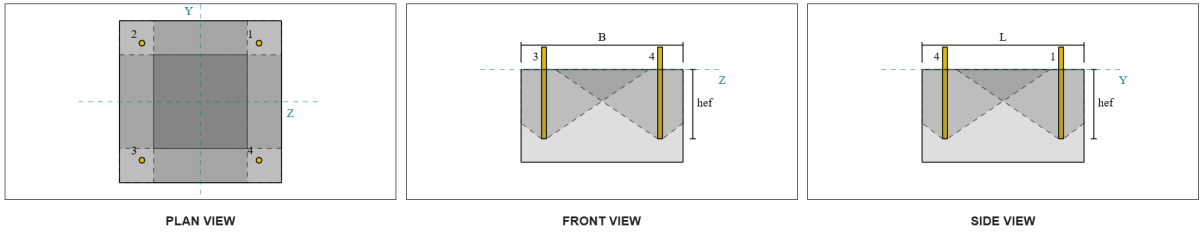
Следовательно, Требуемое сопротивление анкерной группы - это общая результирующая нагрузка на сдвиг 7.07 кН.
\(
V_{резерв} = кврт{(V_Y)^ 2 + (V_Z.)^ 2}
= кврт{(5 \,\текст{кН})^ 2 + (5 \,\текст{кН})^ 2}
знак равно 7.0711 \,\текст{кН}
\)
\(
V_{издание} = слева(\гидроразрыва{V_{резерв}}{n_{anc}}\право) n_{а ,g1}
= слева(\гидроразрыва{7.0711 \,\текст{кН}}{4}\право) \раз 4
знак равно 7.0711 \,\текст{кН}
\)
поскольку 7.0711 кН < 59.478 кН, пропускная способность сдвига достаточный.
Проверьте #5: Рассчитайте сдвиг стержней стержней
Расчет сдвижной емкости якорного стержня зависит от того, применяется ли нагрузка на сдвиг с помощью момента. Чтобы определить это, Мы ссылаемся на В 1992-4:2018, Пункт 6.2.2.3, где толщина и материал раствора, Количество крепеж в дизайне, Расстояние застежков, и другие факторы проверены.
В Программное обеспечение для дизайна базовой плиты Skyciv выполняет все необходимые проверки, чтобы определить, есть ли нагрузка на сдвиг действует с рычагом или без нее. Для этого примера дизайна, определено, что нагрузка на сдвиг нет применяется с рычагом. Следовательно, мы используем В 1992-4:2018, Пункт 7.2.2.3.1, для уравнений пропускной способности.
Начнем с расчета характерного сопротивления стального крепежа с использованием В 1992-4:2018, Уравнение 7.34.
\(
V^0_{Рк,s} = k_6 a_s f_{U,anc}
знак равно 0.5 \раз 113.1 \,\текст{мм}^2 раз 800 \,\текст{МПа}
знак равно 45.239 \,\текст{кН}
\)
следующий, Применяем фактор для пластичность одного якоря или якорной группы, принимающий K7 = 1.
\(
V_{Рк,s} = K_7 V^{0}_{Рк,s}
знак равно 1 \раз 45.239 \,\текст{кН}
знак равно 45.239 \,\текст{кН}
\)
Затем мы получаем Частичный коэффициент сбоя стального сдвига с использованием В 1992-4:2018, Стол 4.1. Для якоря с 8.8 материал, полученный частичный фактор:
\(
\гамма_{РС,сдвиг}
= max left( 1.0 \осталось( \гидроразрыва{F_{U,anc}}{F_{и,anc}} \право), \, 1.25 \право)
= max left( 1 \[object Window]{800 \,\текст{МПа}}{640 \,\текст{МПа}}, \, 1.25 \право)
знак равно 1.25
\)
Применение этого фактора к характерному сопротивлению, Дизайн сопротивления 36.19 кН.
\(
V_{Rd,s} = frac{V_{Рк,s}}{\гамма_{РС,сдвиг}}
= frac{45.239 \,\текст{кН}}{1.25}
знак равно 36.191 \,\текст{кН}
\)
В Требуется сопротивление сдвига Per Anchor Stod - это результирующая нагрузка на сдвиг, деленная на общее количество якорных стержней, который рассчитывает 1.77 кН.
\(
V_{издание} = frac{\SQRT{ (V_Y)^ 2 + (V_Z.)^ 2 }}{n_{anc}}
\)
\(
V_{издание} = frac{\SQRT{ (5 \,\текст{кН})^ 2 + (5 \,\текст{кН})^ 2 }}{4}
знак равно 1.7678 \,\текст{кН}
\)
поскольку 1.7678 кН < 36.191 кН, емкостью сдвига стальной стержней стержней достаточный.
Проверьте #6: Рассчитать несущую способность опорной плиты
Дополнительный проверка сопротивления подшипника опорной плиты был представлен в более позднем обновлении программного обеспечения. Пожалуйста обратитесь к этой ссылке для примерного расчета и подробного пояснения.
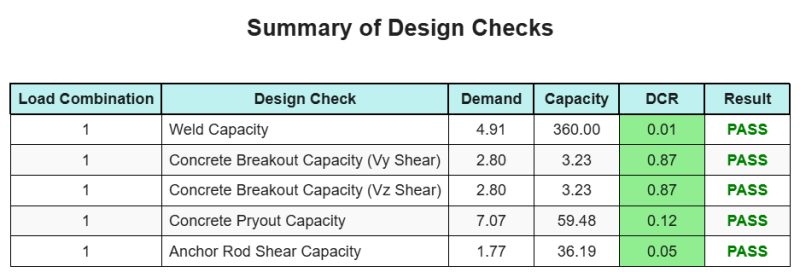
Резюме дизайна
В Программное обеспечение для дизайна базовой плиты Skyciv может автоматически генерировать пошаговый отчет расчета для этого примера проекта. Это также предоставляет краткую информацию о выполненных чеках и их полученных соотношениях, Облегчение информации для понимания с первого взгляда. Ниже приведена примерная сводная таблица, который включен в отчет.
Образец Skyciv
Посмотрите уровень детализации и ясности, который вы можете ожидать от отчета о конструкции базовой пластины SkyCiv.. Отчет включает все ключевые проверки проекта., уравнения, и результаты представлены в ясном и легко читаемом формате.. Полностью соответствует стандартам проектирования.. Нажмите ниже, чтобы просмотреть образец отчета, созданного с помощью калькулятора базовой плиты SkyCiv..
Покупка программного обеспечения для базовой пластины
Купите полную версию модуля дизайна базовой плиты без каких -либо других модулей Skyciv. Это дает вам полный набор результатов для дизайна базовой плиты, в том числе подробные отчеты и больше функциональности.