В этой статье, мы расскажем вам, как определить категорию местности или экспозиции на наветренной стороне местоположения объекта., которые необходимы для расчета ветровых нагрузок. Мы рассмотрим конкретные процедуры, изложенные в ASCE. 7, NBCC 2015, и AS / NZS 1170.2 для определения категорий местности и обсуждения того, как они применяются к каждому ссылочному коду, доступному в генераторе нагрузки SkyCiv..
ASCE 7-16/ASCE 7-22
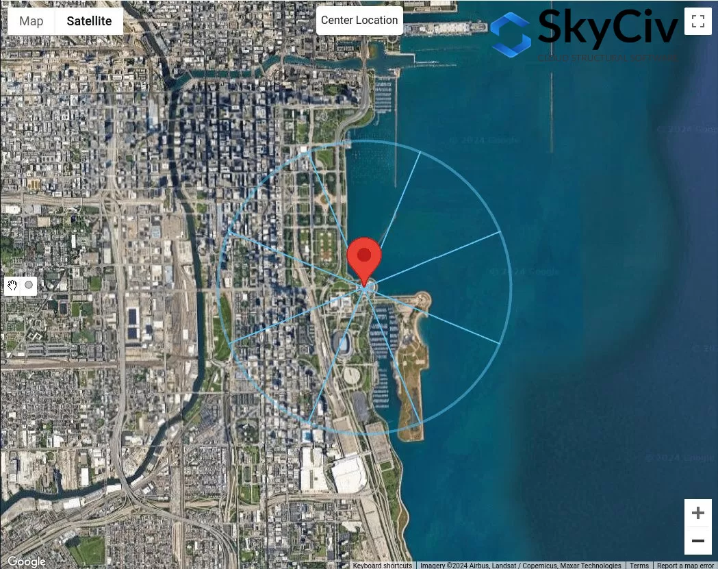
мы обсудим влияние топографии на ветровую нагрузку на конструкции путем расчета топографического фактора 7, Процедура определения категории воздействия для расположения площадки с наветренной стороны обсуждается в разделе 26.7, в зависимости от местности. В этой статье, чтобы упростить ссылку, мы будем использовать ASCE 7-16. Для каждого направления источника ветра, его следует анализировать с двух наветренных секторов, простирающихся на ±45°..
фигура 1. Секторы местности для каждого направления источника ветра.
Для каждого сектора, категорию шероховатости поверхности следует проверять на основе следующего определения, основанного на разделе 26.7.2 ASCE 7-16:
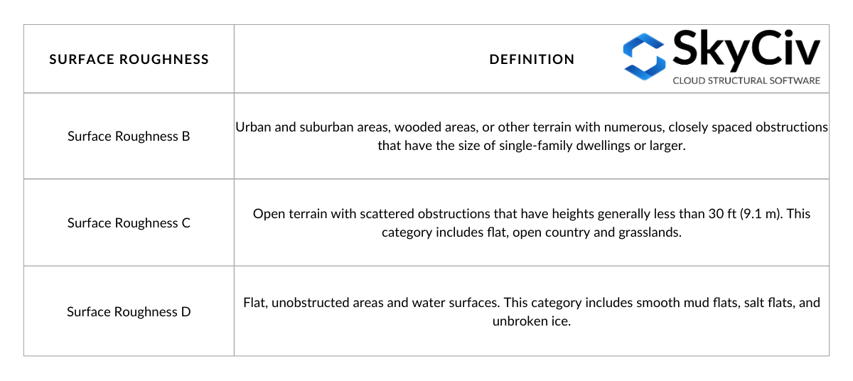
Стол 1. Определение шероховатости поверхности на основе сечения 26.7.2 ASCE 7-16.
Из определения шероховатости поверхности, мы можем определить категорию воздействия местности, ограниченной наветренным сектором. Определение каждой категории воздействия приведено в разделе 26.7.3 ASCE 7-16 следующее:
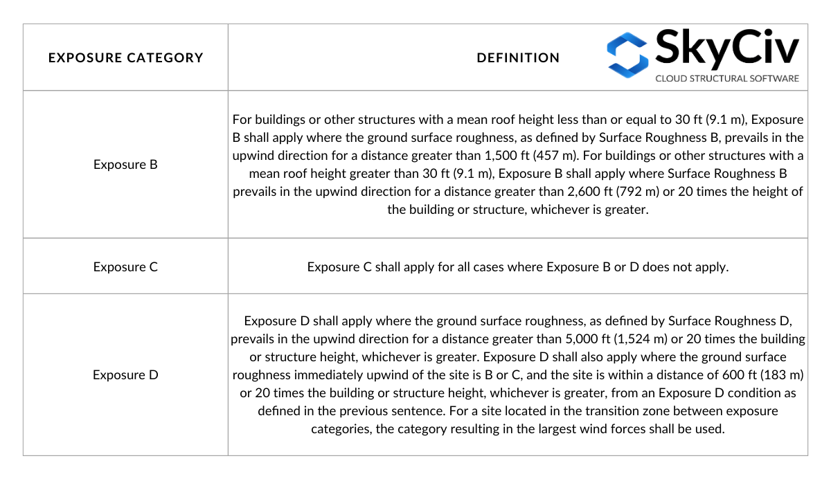
Стол 2. Определение категории воздействия на основе раздела 26.7.3 ASCE 7-16.
Стол 2 можно визуализировать с помощью следующих рисунков, основанных на рисунке C26.7-2.:
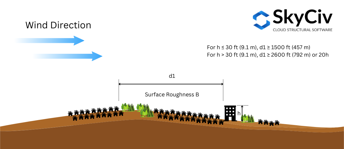
фигура 2. Требования к шероховатости поверхности с наветренной стороны для воздействия B.
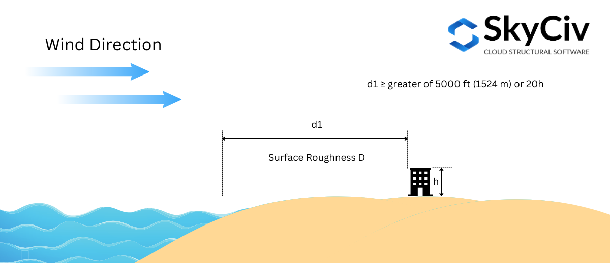
фигура 3. Для воздействия D требуется условие шероховатости поверхности с наветренной стороны. – кейс 1.
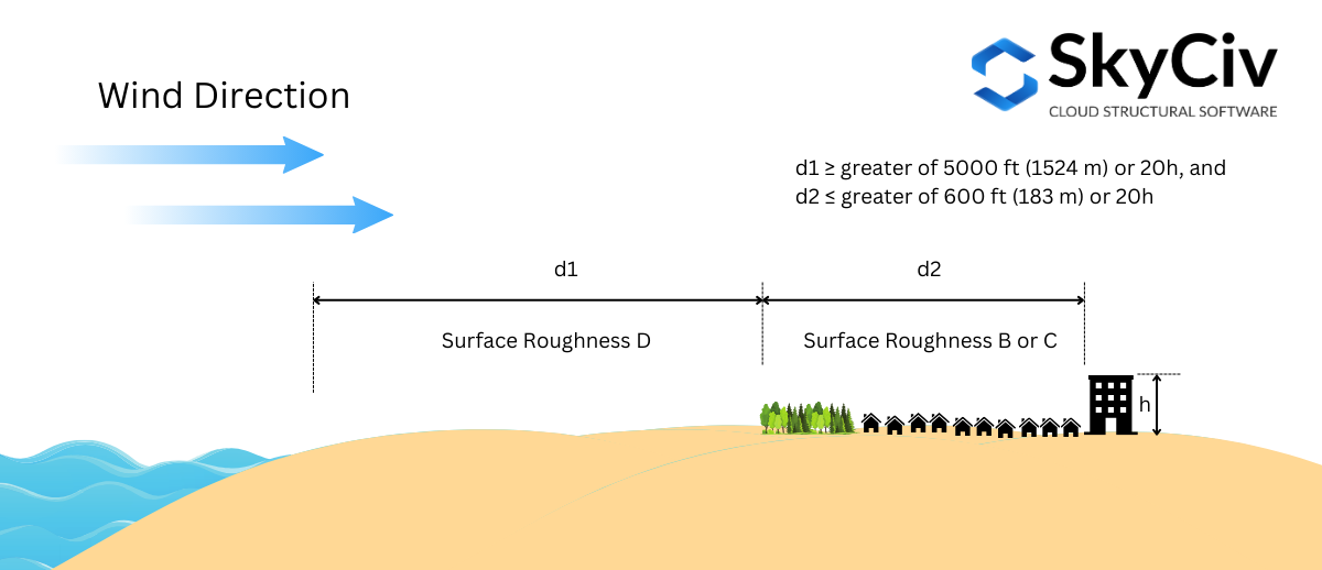
фигура 4. Для воздействия D требуется условие шероховатости поверхности с наветренной стороны. – кейс 2.
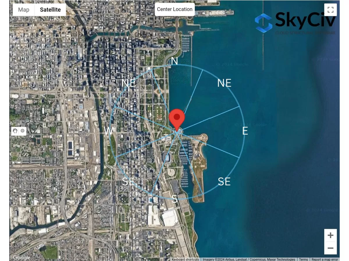
Категория воздействия должна определяться для каждого направления источника ветра.. Использование примера местоположения сайта – “1200 С ДюСейбл Лейк Шор Доктор, Чикаго, НАШИ 60605, Соединенные Штаты Америки”, давайте проанализируем это для каждого направления.
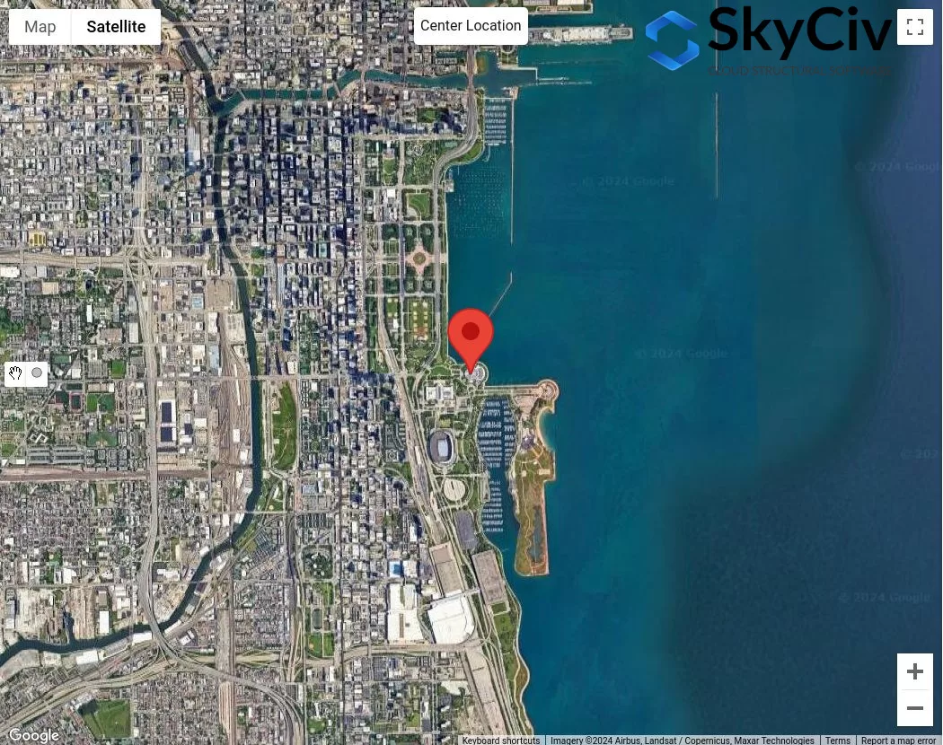
фигура 4. Местоположение образца для анализа категории воздействия.
Предполагая, что средняя высота крыши сооружения равна 25 фут ( \( 20h = 500 фут \)), мы будем использовать следующую процедуру для проверки категории риска для каждого сектора.:
Состояние 1. Определите, соответствует ли экспозиция D, используя рисунок 3:
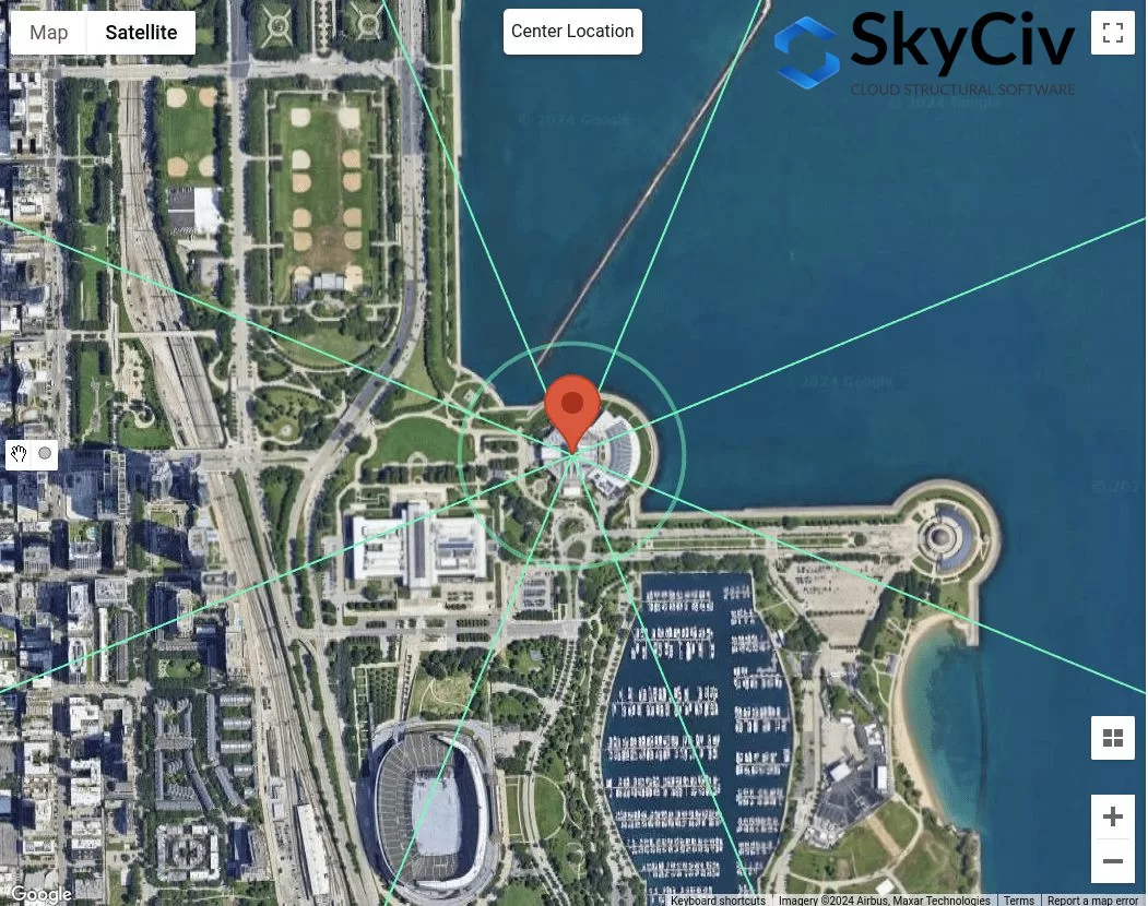
Использование рисунка 3 – где расстояние \( d_{1} \) является 5000 фут (1524 м), нам нужно проверить экспозицию D, где шероховатость поверхности D является доминирующей для всего 5000 фут стрейч:
фигура 5. Расстояние смещения 5000 футов от места установки для проверки воздействия D, используя рисунок 3.
С рисунка 5, мы уже можем сделать вывод, что направления источников ветра N, РОДИЛСЯ, и E иметь шероховатость поверхности D для всего 5000 фут стрейч. Следовательно, эти направления источника ветра Экспозиция D.
Состояние 2. Определите, соответствует ли экспозиция D, используя рисунок 2
Использование рисунка 4 – где расстояние \( d_{1} \) является 5000 фут (1524 м) и расстояние \( d_{2} \) равно 600 фут (183 м), нам нужно проверить экспозицию D. С рисунка 5, это можно применить только для направления источника ветра с юго-востока.:
фигура 6. Расстояние смещения 600 футов и дополнительные 5000 футов от места установки для проверки воздействия D, используя рисунок 4.
Для направления источника ветра ЮВ, с использованием \( d_{2} знак равно 600 фут \), мы можем считать, что этот раздел соответствует шероховатости поверхности B.. тем не мение, на расстояние \( d_{1} знак равно 5000 фут \), раздела нет 100% Шероховатость поверхности D. следовательно, SE не следует рассматривать как риск D..
Состояние 3. Определите, соответствует ли экспозиция B, используя рисунок 1
Использование рисунка 3 – где расстояние \( d_{1} \) является 1500 фут (457 м) поскольку \( час < 30 фут \), нам нужно проверить воздействие B.
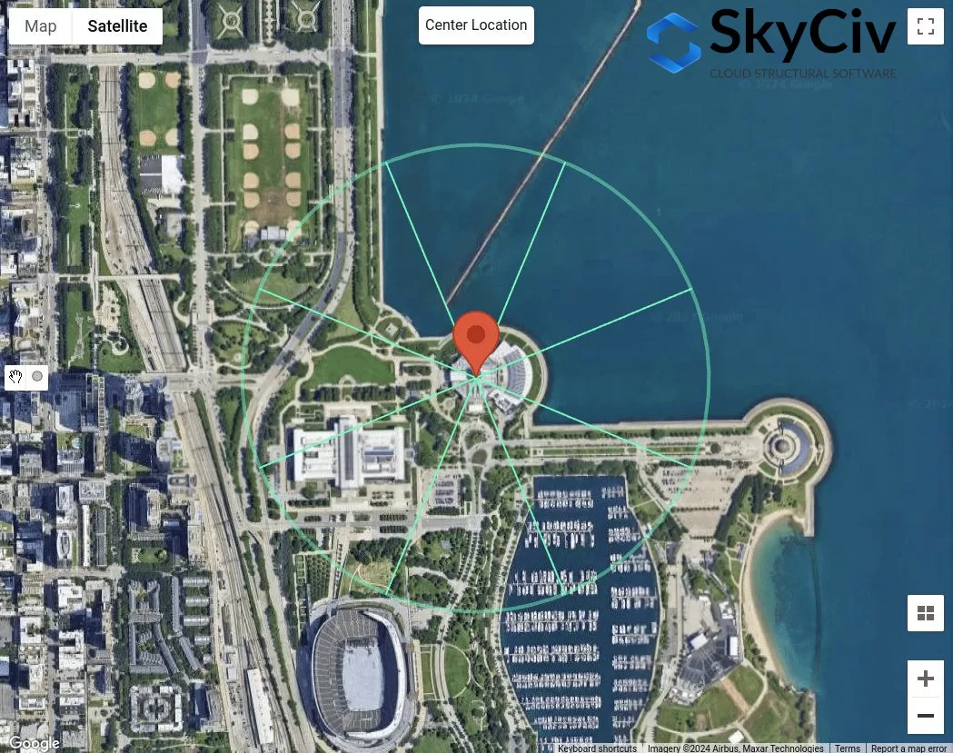
фигура 7. Расстояние смещения 1500 футов от места установки для воздействия B, проверьте, используя рисунок 3.
С рисунка 7, мы можем определить, что для направлений источника ветра СЗ, W, ЮЗ, и S классифицируются как воздействие B, поскольку шероховатость поверхности для каждого сектора направления равна шероховатости поверхности B..
Состояние 4. Если условия 1 в 3 неправда, следовательно, местность - экспозиция C.
Следовательно, для направления источника ветра ЮВ, он классифицируется как категория воздействия C.. В итоге, Категории воздействия для каждого направления источника ветра показаны на рисунке. 8 ниже.
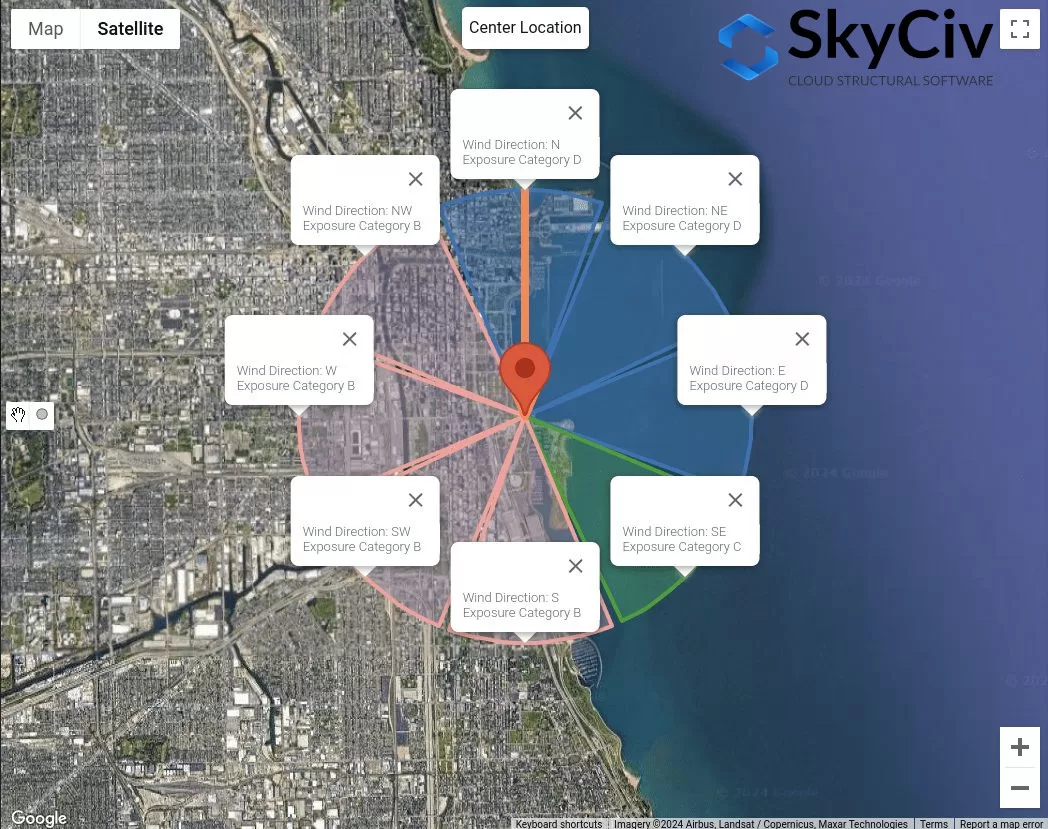
фигура 8. Категории воздействия для каждого направления источника ветра.
Эти данные можно использовать для определения наихудшего направления источника ветра, как коэффициенты скорости и давления. \( Ниже приведены различные способы определения коэффициентов давления грунта для расчета удельного сопротивления трения свай в песке.{с участием} \), Топографический фактор \( Ниже приведены различные способы определения коэффициентов давления грунта для расчета удельного сопротивления трения свай в песке.{T} \), и коэффициент порывов ветра \( грамм \) с использованием подробного расчета зависит от категории воздействия.
NBCC 2015/2020
Для НБКК 2015, Процедура определения категории воздействия для расположения площадки с наветренной стороны обсуждается в разделе 4.1.7.3(5), в зависимости от местности. Для каждого направления источника ветра, его следует анализировать с двух наветренных секторов, простирающихся на ±45°..
фигура 9. Секторы местности для каждого направления источника ветра.
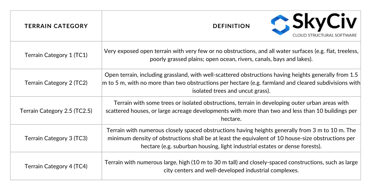
Для каждого сектора, категорию местности следует проверять на основе следующего определения, основанного на разделе 4.1.7.3(5) НБЦК 2015:
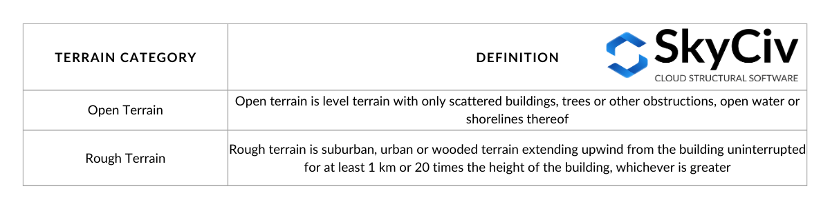
Стол 3. Определение категорий местности, как определено в разделе 4.1.7.3(5) НБЦК 2015.
Визуализация вариантов в таблице 3:
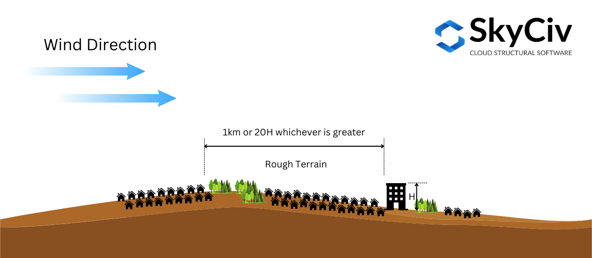
фигура 10. Определение пересеченной местности согласно определению в разделе 4.1.7.3(5) НБЦК 2015.
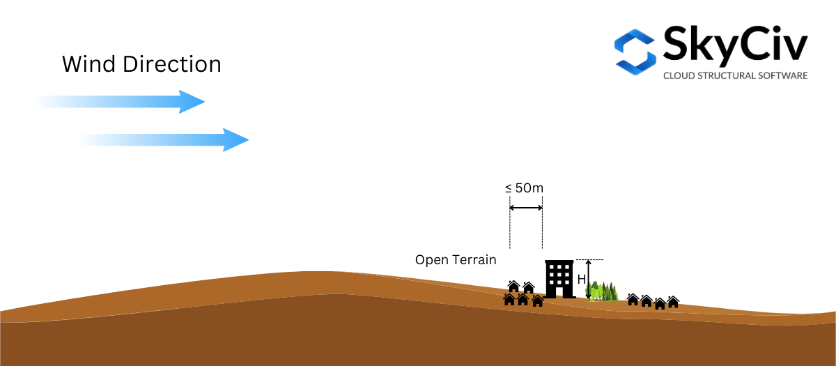
фигура 10. Определение открытой местности согласно определению в разделе 4.1.7.3(5) НБЦК 2015.
На основе раздела 4.1.7.3(5) НБЦК 2015, допускается интерполяция Фактор воздействия \( C_{е} \) на средней местности. Если расстояние по пересеченной местности от места расположения конструкции превышает или равно 1 км или 20 раз больше высоты конструкции, смотря что больше, местность можно рассматривать как пересеченная местность, и если расстояние меньше 50 м, это считается Открытая местность. В противном случае, Фактор воздействия \( C_{е} \) согласно разделу 4.1.7.3(5) будет рассчитываться по граничным значениям. Это можно представить на рисунке 11 ниже.
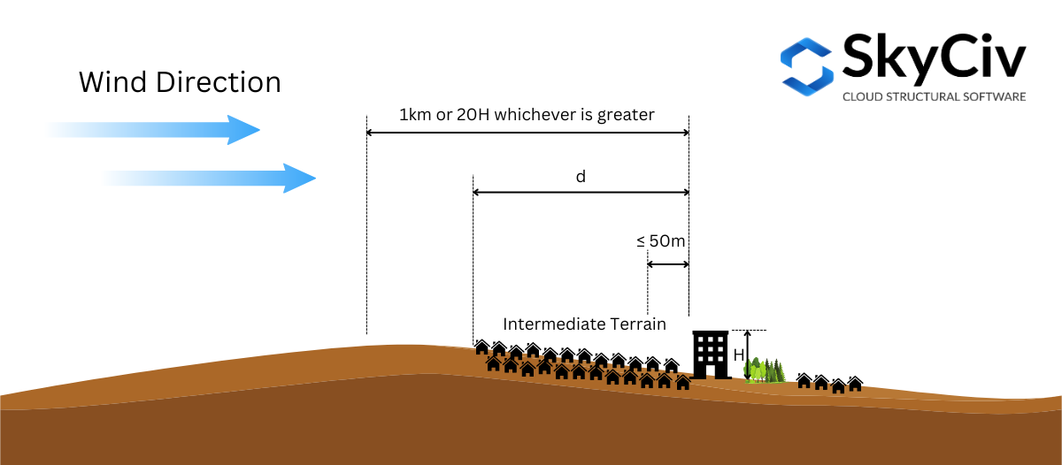
фигура 11. Определение промежуточной местности согласно определению в разделе 4.1.7.3(5) НБЦК 2015.
Чтобы дополнительно проиллюстрировать это, давайте воспользуемся примером местоположения сайта – “657 Мастерс Роуд ЮВ, Калгари, АБ Т3М 2Б6, Канада,” принимая высоту конструкции \( ЧАС \) является 25 м ( \( 20H = 500 м \)).
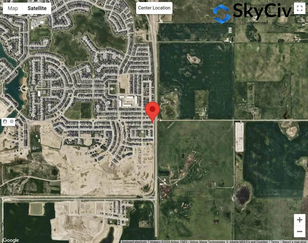
фигура 12. Местоположение образца для анализа категории местности.
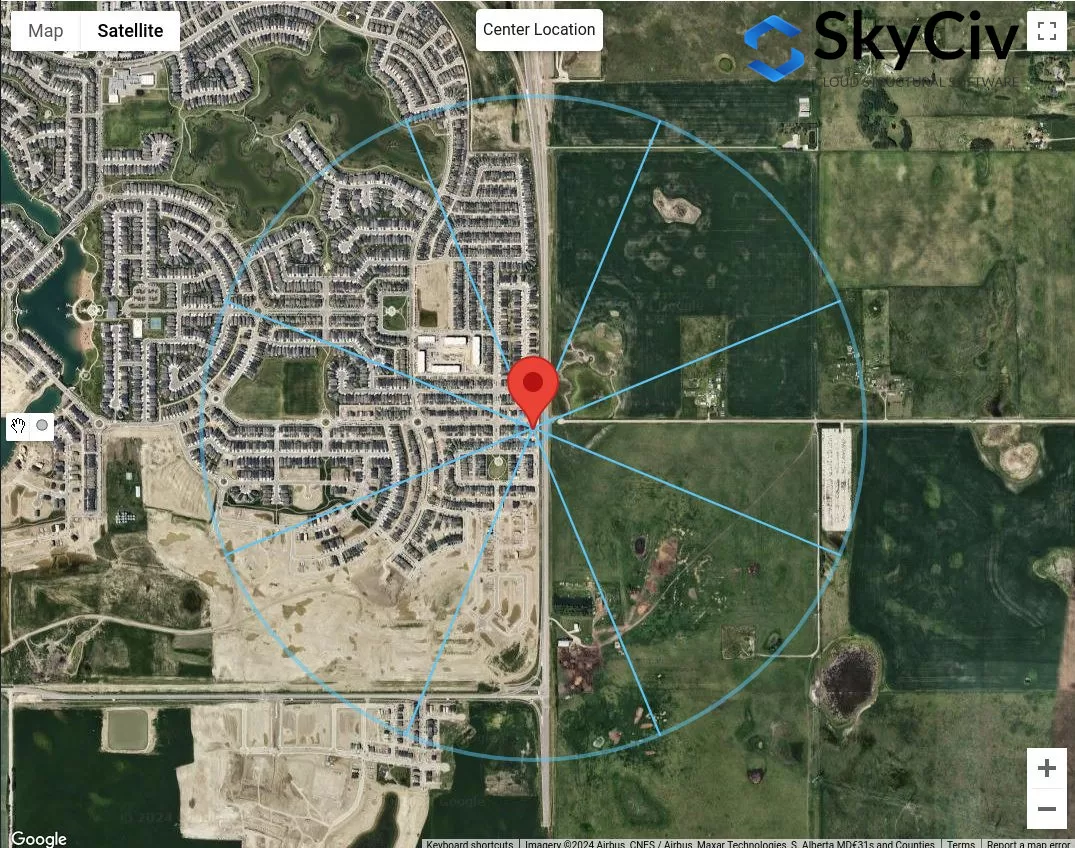
Первым шагом является классификация очевидных категорий пересеченной и открытой местности для каждого направления источника ветра.. Мы можем нарисовать 50 м и максимум 1 км или \( 20 ЧАС \) радиус от местоположения участка.
фигура 13. Расстояние смещения 50 м и 1 км для определения категории местности по таблице 1 определения.
С рисунка 13, можно сказать, что направления источника ветра РОДИЛСЯ, Е, и ЮВ классифицируются как Открытая местность поскольку длина пересеченной местности в каждом направлении составляет менее 50 м от места расположения объекта.. более того, для направления источника ветра З и СЗ можно отнести к категории пересеченной местности, поскольку длина пересеченной местности для этих направлений превышает 1 км. Для направления источника ветра N, мы можем консервативно предположить, что в этом направлении доминирует Open Terrain.. В остальном, Ю и ЮЗ, можем сделать вывод, что это промежуточный рельеф и нам нужно будет измерить расстояние пересеченной местности от места расположения участка.
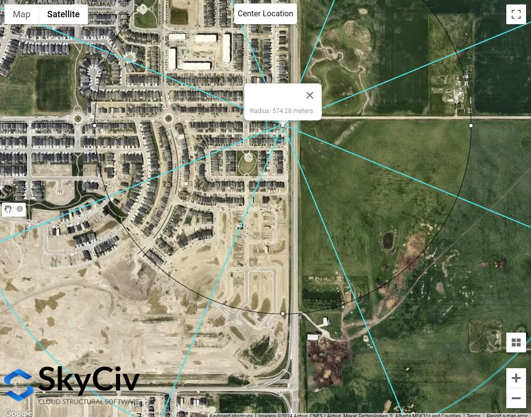
фигура 14. Приблизительная длина пересеченной местности, измеренная от местоположения площадки для направления источника юго-западного ветра, равна 574 м.
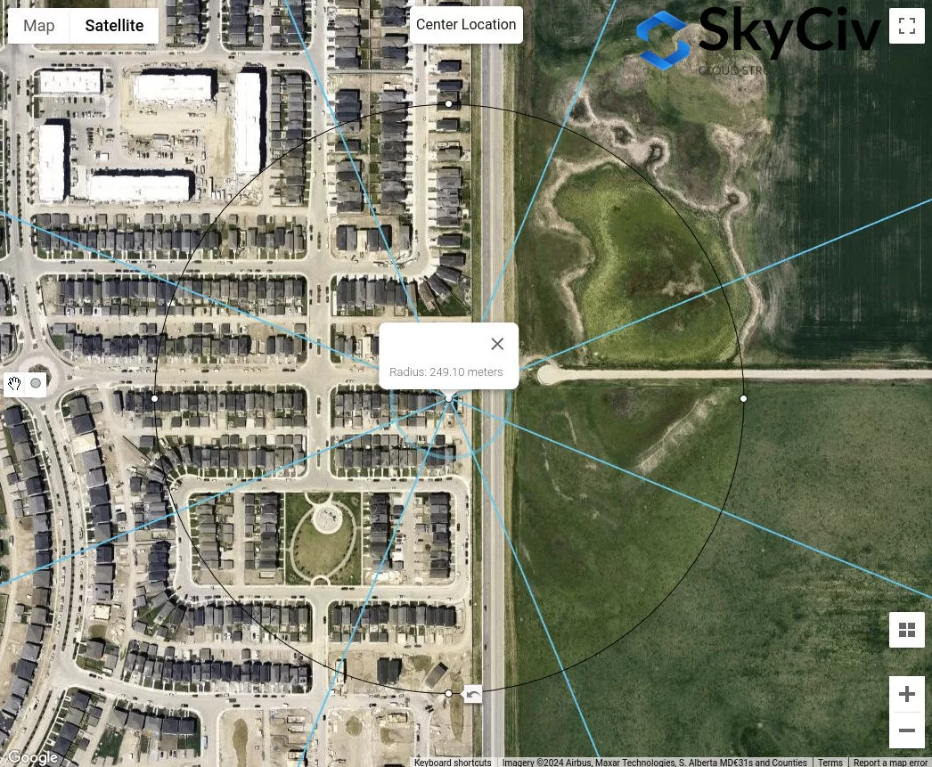
фигура 15. Приблизительная длина пересеченной местности, измеренная от местоположения площадки для направления источника южного ветра, равна 249 м.
Из анализа выше, определенно направления источников ветра с открытой местностью определенно дадут консервативные значения. тем не мение, если все направления источников ветра относятся к средней местности, описанная выше процедура позволяет определить подходящую категорию местности для каждого направления..
AS / NZS 1170.2 (2021)
Для AS / NZS 1170.2, та же процедура с приведенными выше ссылками применяется при определении категории местности с наветренной стороны местоположения площадки.. Это обсуждается в разделе 4.2 AS / NZS 1170.2 (2021). Для каждого направления источника ветра, его следует анализировать с двух наветренных секторов, простирающихся на ±45°.. Определение каждой категории местности показано ниже на основе раздела 4.2.1 AS / NZS 1170.2 (2021):
Стол 4. Определение категорий местности, как определено в разделе 4.2.1 AS / NZS 1170.2 (2021).
При определении категории местности по направлению, расстояние задержки, равное \( 20 с участием \) от расположения конструкции следует пренебречь. С этого момента, расстояние смещения (расстояние усреднения) из 500 м или \( 40 с участием), в зависимости от того, что больше, следует использовать, как показано на рисунке 16 ниже. В \( с участием \) значение равно средней высоте крыши, \( час \), когда оно меньше или равно 25 м. Вполне возможно, что в пределах этого усредненного расстояния будет несколько категорий местности., и как таковой, линейная интерполяция должна использоваться при определении \( M_{с участием,кошка} \) ценности, в зависимости от протяженности каждой категории местности, как показано на рисунке 4.1 AS / NZS 1170.2 (2021). В этой статье, мы будем рассматривать только однородную категорию местности в пределах расстояния осреднения.
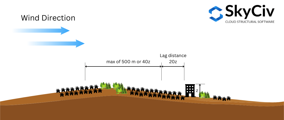
фигура 16. Иллюстрация расстояний, используемых при определении категории местности на основе AS/NZS. 1170.2 (2021).
Чтобы дополнительно проиллюстрировать это, давайте воспользуемся примером местоположения сайта – лат.: 32°43’46″С Ланг: 151°31’47″Е – принимая среднюю высоту крыши \( час \) является 10 м ( где \( 20г = 20ч = 200 м \) и \( 40г = 400 м \)).
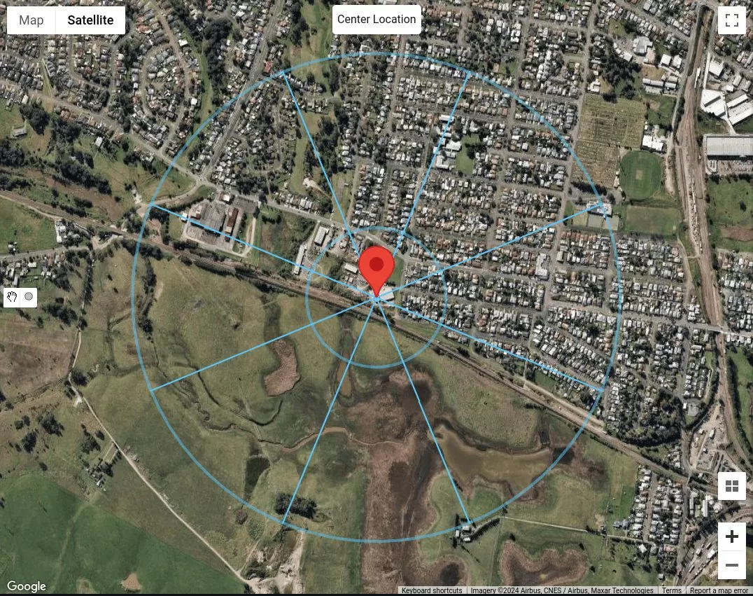
фигура 17. Местоположение площадки с расстоянием лага, равным 200 м и расстояние осреднения равное 500 м для каждого направления источника ветра.
Поскольку нам следует рассматривать категорию местности как однородную на протяжении всего 500 м или \( 40с участием \) расстояние, мы уже можем классифицировать каждое направление источника ветра. Предположим, что здания на N, СВ и В, это здания, которые 5 в 10 м высотой, мы можем отнести их к категории местности. 3 (ТС3) как показано в таблице 4. Для направлений источника ветра ЮВ, S, ЮЗ, и В, так как это травяные равнины без препятствий, мы можем классифицировать их как категорию местности. 1 (ТК1). В завершение, для направления источника ветра СЗ, мы можем сделать вывод, что их больше двух, но меньше 10 построек на гектар, с разбросанными домами. Следовательно, мы можем классифицировать это как категорию местности 2.5 (ТК2.5).
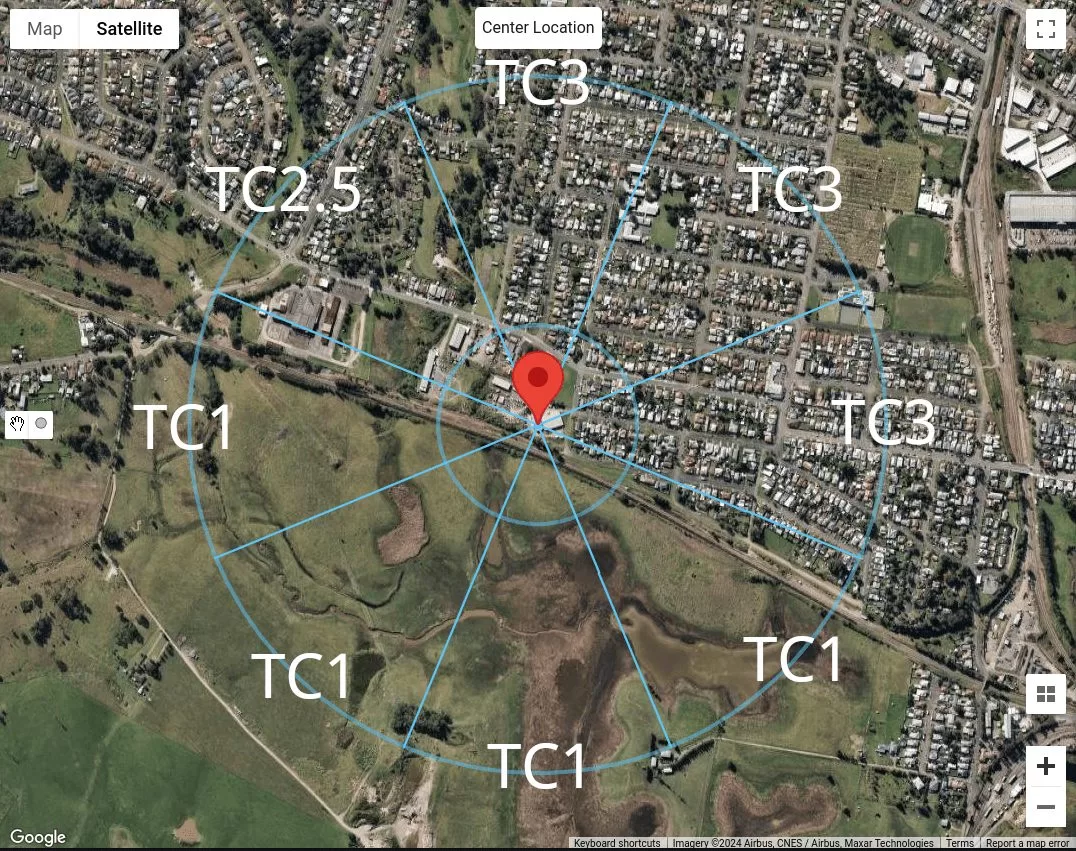
фигура 18. Сводная информация о классификации категорий местности для каждого направления источника ветра для нашей выборки..
Использование генератора нагрузки SkyCiv
В генераторе нагрузки SkyCiv версии v4.7.0, представлены новые инструменты карты – Измерить расстояние и Расстояние Радиусы инструменты.
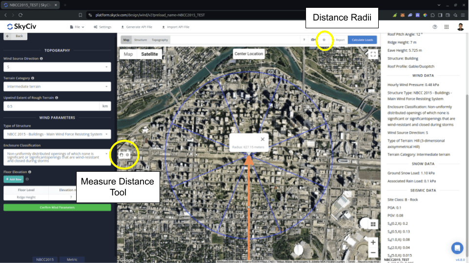
фигура 19. Инструменты измерения расстояния представлены в генераторе нагрузки SkyCiv.
В Измерить расстояние инструмент используется для создания круга из выбранной точки на карте и отображения его радиуса в метрах.. Сюда, вы можете измерить расстояния от анализируемого местоположения в определенных местах. Это можно использовать при измерении в NBCC. 2015 для Протяженность пересеченной местности с наветренной стороны используется при расчете Фактор воздействия \( C_{е} \). Нажатие на созданный круг уберет его с карты..
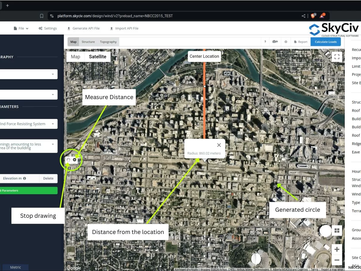
фигура 20. Инструмент измерения расстояния, который создает смещение от местоположения и показывает радиус/расстояние смещения от центра, представленный в генераторе нагрузки SkyCiv..
С другой стороны, в Расстояние Радиусы введено, чтобы пользователи могли рисовать круги с указанными расстояниями от местоположения для каждой категории источников ветра.. Это кнопка переключения, позволяющая показать или скрыть радиусы расстояний на карте., с местоположением сайта в центре кругов.
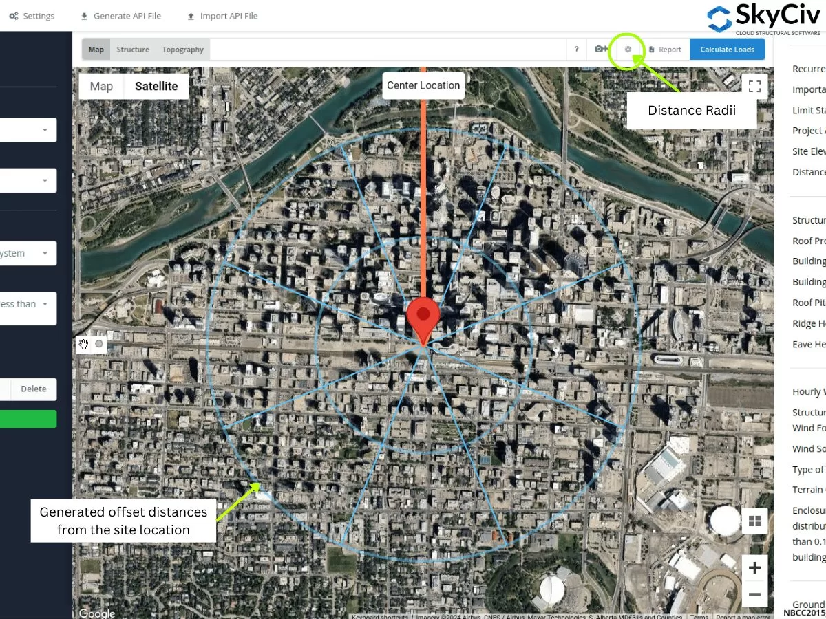
фигура 21. Инструмент Distance Radii, указывающий расстояния смещения от местоположения объекта, представленный в генераторе нагрузки SkyCiv..
Значения радиусов можно редактировать после открытия настроек..
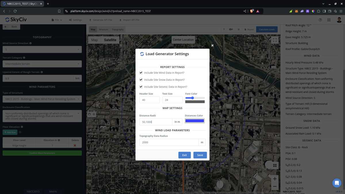
фигура 22. Возможность в настройках редактировать расстояния для инструмента «Радиусы расстояний» в генераторе нагрузки SkyCiv..
Обратите внимание, что пользователи должны редактировать значения расстояния, поскольку они не рассчитываются автоматически программным обеспечением.. Использование этого для ASCE 7 и NBCC, должна быть принята наихудшая категория воздействия или местности для каждого направления источника ветра.. Что касается его использования в AS/NZS 1170.2 (2021), программное обеспечение не использует значения радиусов для расчета среднего значения \( M_{с участием,кошка} \) ценности. Вместо, расстояние усреднения используется в качестве применимого диапазона, в котором мы можем назначить однородную категорию местности., принятие худшей категории для каждого направления источника ветра.
Из разделов, рассмотренных выше, вы можете использовать эти новые инструменты для определения категорий экспозиции или местности для каждого направления источника ветра.. Вышеописанные процедуры могут дать вам быструю классификацию местности для каждого направления источника ветра.. Использование инструментов ГИС и искусственного интеллекта, вы можете дополнительно проверить критерии, которые мы использовали выше для каждого направления источника ветра, и получить лучший и эффективный результат..

Инженер-строитель, Разработка продукта
MS Гражданское строительство
Ссылки:
- Минимальные проектные нагрузки для зданий и других сооружений. (2017). ASCE / SEI 7-16. Американское общество гражданских инженеров.
- Национальный исследовательский совет Канады. (2015). Национальный строительный кодекс Канады, 2015. Национальный исследовательский совет Канады.
- Стандарты Австралии (2021), Действия по структурному проектированию. Часть 2 Действия ветра, Стандарт Австралии/Новозеландии AS/NZS1170.2:2021, Стандарты Австралии, Сидней, Новый Южный Уэльс, Австралию.
- = Расстояние с подветренной стороны от гребня до места, где перепад высот составляет половину высоты холма или откоса.