Пример дизайна базовой плиты с использованием en 1993-1-8-2005, В 1993-1-1-2005 и EN 1992-1-1-2004
Запись о проблеме
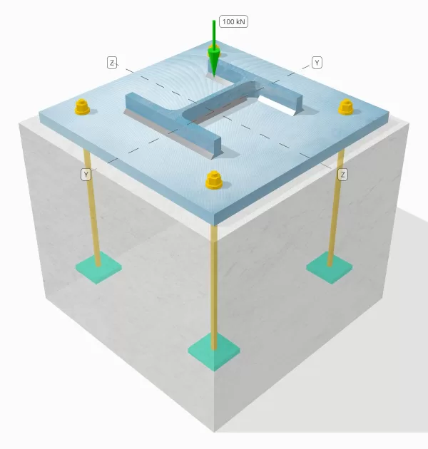
Определите, достаточным ли разработанное соединение с столбцом-базой для нагрузки с компрессионной нагрузкой на 100 кН..
Данные данных
Столбец:
Раздел столбца: ОН 200 В
Область столбца: 7808 мм2
Материал столбца: S235
Опорная плита:
Размеры опорной плиты: 400 мм х 400 мм
Толщина опорной плиты: 20 мм
Материал опорной плиты: S235
Раствор:
Толщина затирки: 20 мм
бетон:
Бетонные размеры: 450 мм х 450 мм
Бетонная толщина: 380 мм
Бетонный материал: С20/25
Швы:
Нагрузка сжатия переносится только через сварные швы? НЕТ
Модель в бесплатном инструменте SkyCiv
Смоделируйте конструкцию опорной плиты, указанную выше, с помощью нашего бесплатного онлайн-инструмента сегодня.! Регистрация не требуется.
Пошаговые расчеты
Проверьте #1: Рассчитайте емкость сварки
Поскольку нагрузка сжатия не переносится только через сварные швы, Надлежащая поверхность контактного подшипника требуется, чтобы гарантировать, что нагрузка переносится через подшипник. Обратиться к В 1090-2:2018 Пункт 6.8 для подготовки к контакту.
Дополнительно, используйте минимальный размер сварного шва указано в Еврокоде.
Проверьте #2: Рассчитать несущую способность бетона и предел текучести опорной плиты.
Первым делом необходимо определить расчетную прочность соединения на сжатие., что зависит от геометрии опоры (бетон) и геометрия нагруженной области (опорная плита).
Начнем с расчета альфа-фактора, что объясняет диффузию сосредоточенной силы внутри фундамента.
В соответствии с В 1992-1-1:2004, Пункт 6.7, коэффициент альфа - это отношение нагруженной площади к максимальной площади распределения, который имеет форму, похожую на нагруженную область.
Мы будем использовать уравнение из Часть 6.1 части многоэтажных стальных зданий 5 по Арселор Миттал, Пейн перевозчик, и Корус рассчитать альфа-фактор.
\(
\альфа = мин лево(
1 + \гидроразрыва{т_{\текст{концентрация}}}{\Максимум(L_{\текст{бп}}, B_{\текст{бп}})},
1 + 2 \осталось( \гидроразрыва{э_ч}{L_{\текст{бп}}} \право),
1 + 2 \осталось( \гидроразрыва{е_б}{B_{\текст{бп}}} \право),
3
\право)
\)
\(
\альфа = мин лево(
1 + \гидроразрыва{380 \, \текст{мм}}{\Максимум(400 \, \текст{мм}, 400 \, \текст{мм})},
1 + 2 \осталось( \гидроразрыва{25 \, \текст{мм}}{400 \, \текст{мм}} \право),
1 + 2 \осталось( \гидроразрыва{25 \, \текст{мм}}{400 \, \текст{мм}} \право),
3
\право)
\)
\(
\альфа = 1.125
\)
где,
\(
e_h = frac{L_{\текст{концентрация}} – L_{\текст{бп}}}{2} = frac{450 \, \текст{мм} – 400 \, \текст{мм}}{2} знак равно 25 \, \текст{мм}
\)
\(
e_b = frac{B_{\текст{концентрация}} – B_{\текст{бп}}}{2} = frac{450 \, \текст{мм} – 400 \, \текст{мм}}{2} знак равно 25 \, \текст{мм}
\)
Как только геометрия определена, затем мы определим прочность бетона на сжатие, используя В 1992-1-1:2004, уравнение. 3.15.
\(
f_{CD} = frac{\альфа_{cc} f_{ск}}{\Gamma_c} = frac{1 \раз 20 \, \текст{МПа}}{1.5} знак равно 13.333 \, \текст{МПа}
\)
следующий, мы принимаем значение бета-коэффициента. Так как затирка присутствует, значение бета может быть 2/3. Расчетную несущую способность соединения рассчитаем по комбинированным формулам из В 1993-1-8:2005 уравнение. 6.6, и В 1992-1-1:2004 уравнение. 6.63.
\(
f_{Джейд} = beta alpha f_{CD} знак равно 0.66667 \раз 1.125 \раз 13.333 \, \текст{МПа} знак равно 10 \, \текст{МПа}
\)
Вторая часть включает расчет предела текучести опорной плиты..
Так как у нас уже есть расчетная несущая способность соединения, мы будем использовать это для определения наименьшего консольного расстояния опорной плиты, которая испытывает полную несущую нагрузку.. Мы будем обращаться к СКИ П358 пример на странице 243 и В 1993-1-1:2005 Пункт 6.2.5.
\(
с = т_{\текст{бп}} \SQRT{\гидроразрыва{f_{y_{\текст{бп}}}}{3 f_{Джейд} \гамма_{М0}}} знак равно 20 \, \текст{мм} \раз sqrt{\гидроразрыва{225 \, \текст{МПа}}{3 \раз 10 \, \текст{МПа} \раз 1}} знак равно 54.772 \, \текст{мм}
\)
Мы будем использовать этот размер для расчета эффективной площади опорной плиты.. 'c’ Рассчитанный нами размер может перекрываться или не перекрываться возле фланца. Если оно перекрывается, будем считать, что сечение прямоугольное.. Если оно не пересекается, мы возьмем форму колонны.
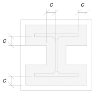
Без перекрытия
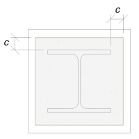
С перекрытием
Мы определили, что «c’ размерность не перекрывается. Следовательно, с использованием SCI P358 стр.. 243, эффективная площадь:
\(
А_е = 4с^2 + П_{\текст{полковник}}с + A_{\текст{полковник}} знак равно 4 \раз 54,772^2 \, \текст{мм}^ 2 + 1182 \, \текст{мм} \раз 54.772 \, \текст{мм} + 7808 \, \текст{мм}^ 2 = 84549 \, \текст{мм}^ 2
\)
Важно отметить, что эффективная площадь не должна быть меньше площади опорной плиты..
В завершение, мы будем использовать В 1993-1-8:2005 уравнение. 6.6, и EN 1992-1-1:2004, уравнение. 6.63 рассчитать расчетную несущую способность соединения опорной плиты.
\(
N_{Rd} = слева( \мин(А_е, А_0) \право) f_{Джейд} = слева( \мин(84549 \, \текст{мм}^ 2, 160000 \, \текст{мм}^ 2) \право) \раз 10 \, \текст{МПа} знак равно 845.49 \, \текст{кН}
\)
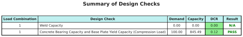
поскольку 845.49 кН > 100 кН, дизайн достаточный!
Резюме дизайна
Программное обеспечение для проектирования базовых плитов Skyciv может автоматически генерировать пошаговый отчет расчета для этого примера проекта. Это также предоставляет краткую информацию о выполненных чеках и их полученных соотношениях, Облегчение информации для понимания с первого взгляда. Ниже приведена примерная сводная таблица, который включен в отчет.
Образец Skyciv
Посмотрите уровень детализации и ясности, который вы можете ожидать от отчета о конструкции базовой пластины SkyCiv.. Отчет включает все ключевые проверки проекта., уравнения, и результаты представлены в ясном и легко читаемом формате.. Полностью соответствует стандартам проектирования.. Нажмите ниже, чтобы просмотреть образец отчета, созданного с помощью калькулятора базовой плиты SkyCiv..
Покупка программного обеспечения для базовой пластины
Купите полную версию модуля дизайна базовой плиты без каких -либо других модулей Skyciv. Это дает вам полный набор результатов для дизайна базовой плиты, в том числе подробные отчеты и больше функциональности.