
General Settings
The settings of SkyCiv Structural 3D control the units, graphics, modelling behaviour, solver options, status bar and mouse controls of your 3D structural analysis software. This page explains every option of the Settings dialog, and the Visibility Settings panel (with its keyboard shortcuts) that controls what is drawn on your model.
Open the dialog by clicking Settings in the top bar:

The dialog has six tabs: Units, View, Modelling, Solver, Status Bar and Controls. To find an option quickly, type its name in the Search for a setting… box at the top of the dialog. Click Save to apply your changes, or Cancel to close the dialog without them.
Units Settings
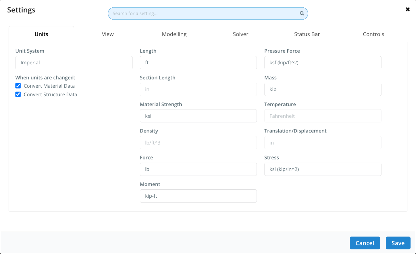
- Unit System: Choose between Metric and Imperial. Changing it switches every unit below to the defaults of that system (for example kN, m and MPa for Metric; kip, ft and ksi for Imperial).
- Convert Material Data: When this is ticked, the values of your materials are converted to the new unit system when you change it.
- Convert Structure Data: When this is ticked, the other values of the model (node coordinates, sections, loads and so on) are converted to the new unit system when you change it.
- Individual units: Within the chosen system, pick the unit for each quantity: Length, Section Length, Material Strength, Density, Force, Moment, Pressure Force, Mass, Temperature, Translation/Displacement and Stress. For example, a metric model can use mm for lengths and N for forces. Quantities with only one unit in a system are greyed out.
View Settings
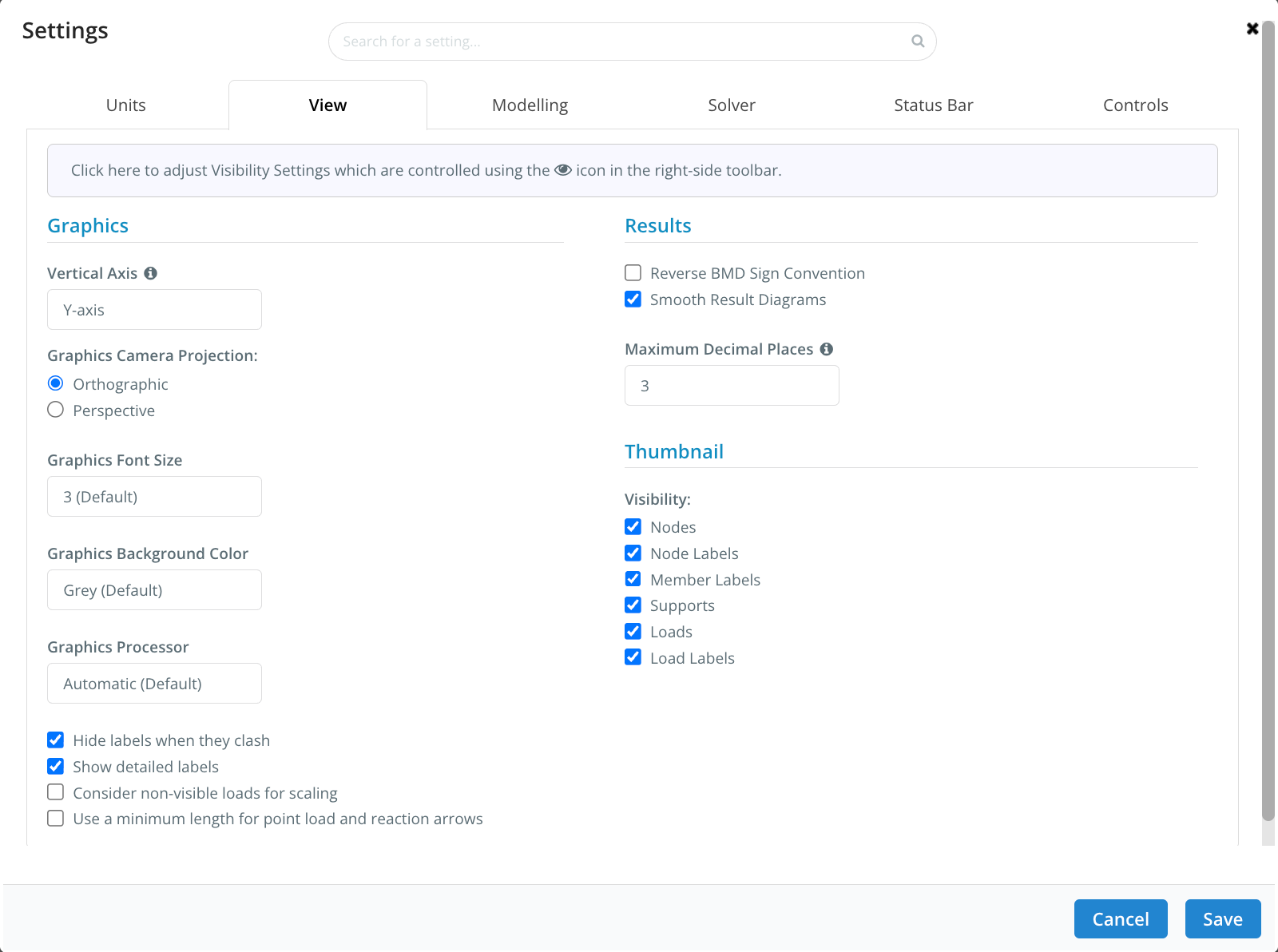
The View tab controls how the model and the results are drawn. The link at the top of the tab opens the Visibility Settings (described below), which control which elements are shown.
Graphics
- Vertical Axis: Choose whether Y-axis or Z-axis is the global vertical axis. This often depends on your region.
- Graphics Camera Projection: Orthographic (the default) or Perspective. Perspective looks more realistic, but orthographic makes it easier to judge 3D coordinates and lengths.
- Graphics Font Size: The size of the labels in the model space (node, member and load labels), from 1 to 5. The default is 3.
- Graphics Background Color: White, Gradient Blue, Grey (Default), Dark or Black.
- Graphics Processor: Automatic (Default), GPU or CPU. The renderer in use is shown in the status bar at the bottom of the screen.
- Hide labels when they clash: Only show one label when several labels occupy the same space.
- Show detailed labels: Show the detailed version of labels where one exists.
- Consider non-visible loads for scaling: Include loads that are hidden when working out the drawing scale of the loads.
- Use a minimum length for point load and reaction arrows: Make sure point load and reaction arrows are never drawn smaller than a minimum length.
Results
- Reverse BMD Sign Convention: Reverse the sign convention of the bending moment diagrams.
- Smooth Result Diagrams: Fit a smooth curve through the result diagrams.
- Maximum Decimal Places: The number of decimal places that results are rounded to, on the diagrams and in the text report. The default is 3.
Thumbnail
- Visibility: Choose what is drawn in the thumbnail of the model that appears in the file manager and on the title page of the analysis report PDF: Nodes, Node Labels, Member Labels, Supports, Loads and Load Labels.
Modelling Settings
General
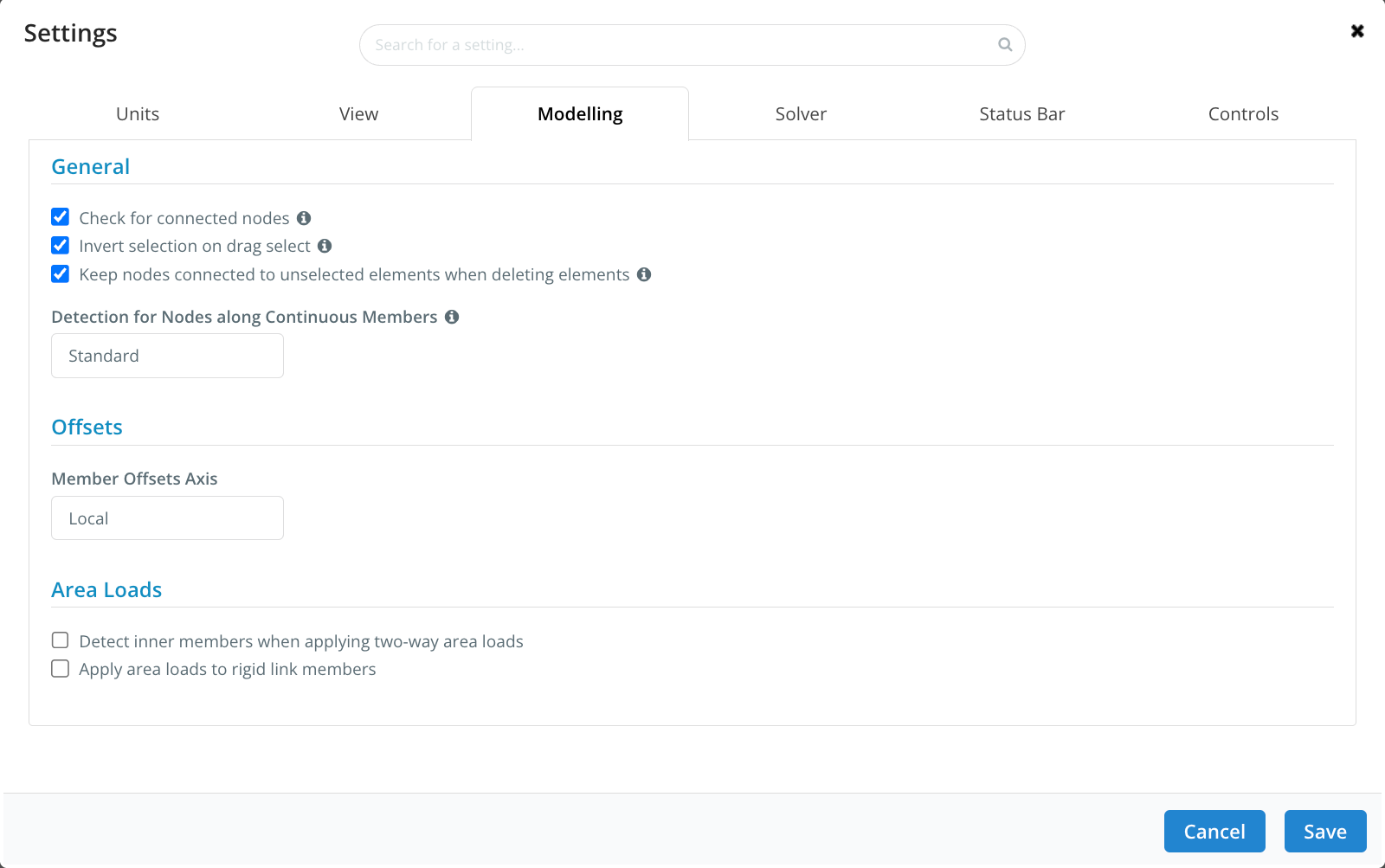
- Check for connected nodes: When you move nodes, the software detects connected nodes and moves them along. You can undo this automatic adjustment at any time with Ctrl + Z.
- Invert selection on drag select: When you drag select with the mouse, re-selecting an element that is already selected deselects it.
- Keep nodes connected to unselected elements when deleting elements: When this is turned off, deleting nodes also deletes every element that depends on them, even if those elements weren’t selected.
- Detection for Nodes along Continuous Members: Standard, or Level 1 to Level 5. A higher level uses a tighter tolerance to detect nodes along continuous members.
Offsets
- Member Offsets Axis: Whether member offsets are entered in the member’s Local axes or in the Global axes.
Area Loads
- Detect inner members when applying two-way area loads: Include the members inside the area when distributing two-way area loads.
- Apply area loads to rigid link members: Allow area loads to be distributed onto rigid link members.
Solver Settings
These settings control how the solver analyzes your model. The Solver tab is only available with a SkyCiv account.
General Solver
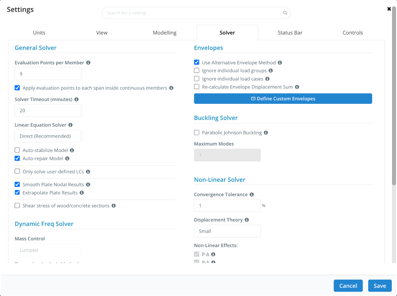
- Evaluation Points per Member: The number of points along each member where results are calculated (3 to 51, default 9). More points give more accurate results but a slower solve and a less responsive model. Use an odd number so that the middle of the member is evaluated: 9 for smaller structures, 5 for larger ones.
- Apply evaluation points to each span inside continuous members: When ticked (the default), the evaluation points are used for each span of a continuous member. When not ticked, they are spread over the whole continuous member.
- Solver Timeout (minutes): The maximum time the solver can run before it times out, from 1.5 to 40 minutes (default 20). Increase it for very large structures.
- Linear Equation Solver: Direct (Recommended), Indirect or Indirect (Legacy). The direct solver is the fastest in most cases. The indirect solver can be faster for some models, depending on their condition.
- Auto-stabilize Model: The solver tries to automatically stabilize nodes that are not restrained. Turn this on if your model has stability issues, especially if a non-linear analysis won’t converge. Leave it off otherwise.
- Auto-repair Model: Run the Repair Model tool automatically before every solve. On by default.
- Only solve user-defined LCs: Skip the individual load cases and load groups and only solve your load combinations. This reduces the solve time of large structures, since fewer result sets are solved.
- Smooth Plate Nodal Results: Smooth the discontinuities between adjacent plate elements by averaging their nodal results.
- Extrapolate Plate Results: Extrapolate plate forces and stresses from the Gauss points to the nodes. Turn it off to keep the results at the Gauss points.
- Shear stress of wood/concrete sections: Calculate the shear stress of wood and concrete members. Turning it off reduces the file size of models with many wood or concrete sections. If you turn it back on, re-submit those sections in the Section Builder to fetch their shear properties again.
Dynamic Freq Solver (see Dynamic Frequency Analysis)
- Mass Control: The mass idealization used for the dynamic analysis. Currently fixed to Lumped.
- Eigenvalue Analysis Method: The algorithm used to solve the eigenvalues. Currently fixed to Lanczos.
- Maximum Modes: The maximum number of modes the dynamic frequency analysis returns (default 10). It may return fewer if those modes don’t exist.
- Vertical Cutoff: Any part of the structure below this vertical level is ignored by the dynamic frequency analysis.
- Area Red. Fac. for T/C only members: Tension-only and compression-only members are included in the dynamic frequency analysis. This factor reduces their area, and so their axial stiffness, since they are usually bracing.
Envelopes
- Use Alternative Envelope Method: When ticked (the default), each element’s envelope results all come from its single worst load combination. When not ticked, the worst value is found at every point along the element, so one element’s envelope can come from more than one load combination.
- Ignore individual load groups: Leave the individual load groups out of the envelope results and the results summary.
- Ignore individual load cases: Leave the individual load cases out of the envelope results and the results summary.
- Re-calculate Envelope Displacement Sum: Recalculate the total displacement of each envelope from its X, Y and Z deflections.
- Define Custom Envelopes: Opens a window to define your own envelopes.
Buckling Solver
- Parabolic Johnson Buckling: Use the parabolic (J.B. Johnson) formula, a more conservative approach for the buckling of intermediate-length columns. It is applied for critical stresses above half the yield strength.
- Maximum Modes: The number of buckling modes. Currently fixed to 1.
Non-Linear Solver (see Non-Linear Static (P-Delta) Analysis)
- Convergence Tolerance: The non-linear analysis keeps iterating until this relative error (in %) is met. The default is 1%. A smaller value takes longer to converge.
- Displacement Theory: Small (the default) or Finite. Finite displacement theory takes the full movement of the members into account and suits large displacements. When displacements are small, both give almost the same results.
- Non-Linear Effects: Show which effects are considered: P-Δ, P-δ and Axial Shortening. You can’t toggle them: they follow the displacement theory you choose.
Results Summary
- Building Slenderness Check: Use the governing global displacement to check the building slenderness, shown in the results summary.
- LCs to use for the Building Slenderness Check: All (every load combination, load case and load group) or Only Serviceability Load Combinations (the default).
- Building Slenderness Limit: The limit, as h / the value you enter (default h / 300).
Status Bar Settings
The status bar runs along the bottom of the screen. The Status Bar tab is only available with a SkyCiv account.
- Status Bar Message Style: How messages appear in the status bar: None, Flash (Default), Glowing Pulse, Normal Bar, Double Bar or Elastic Bar.
- Items in the Status Bar: Turn on the items to show: File Name, Auto-Save, Units, Unit System Name, Element Count, Graphics Projection, Success Messages and Error Messages.
Controls Settings
These settings adjust how the mouse moves around the model space.
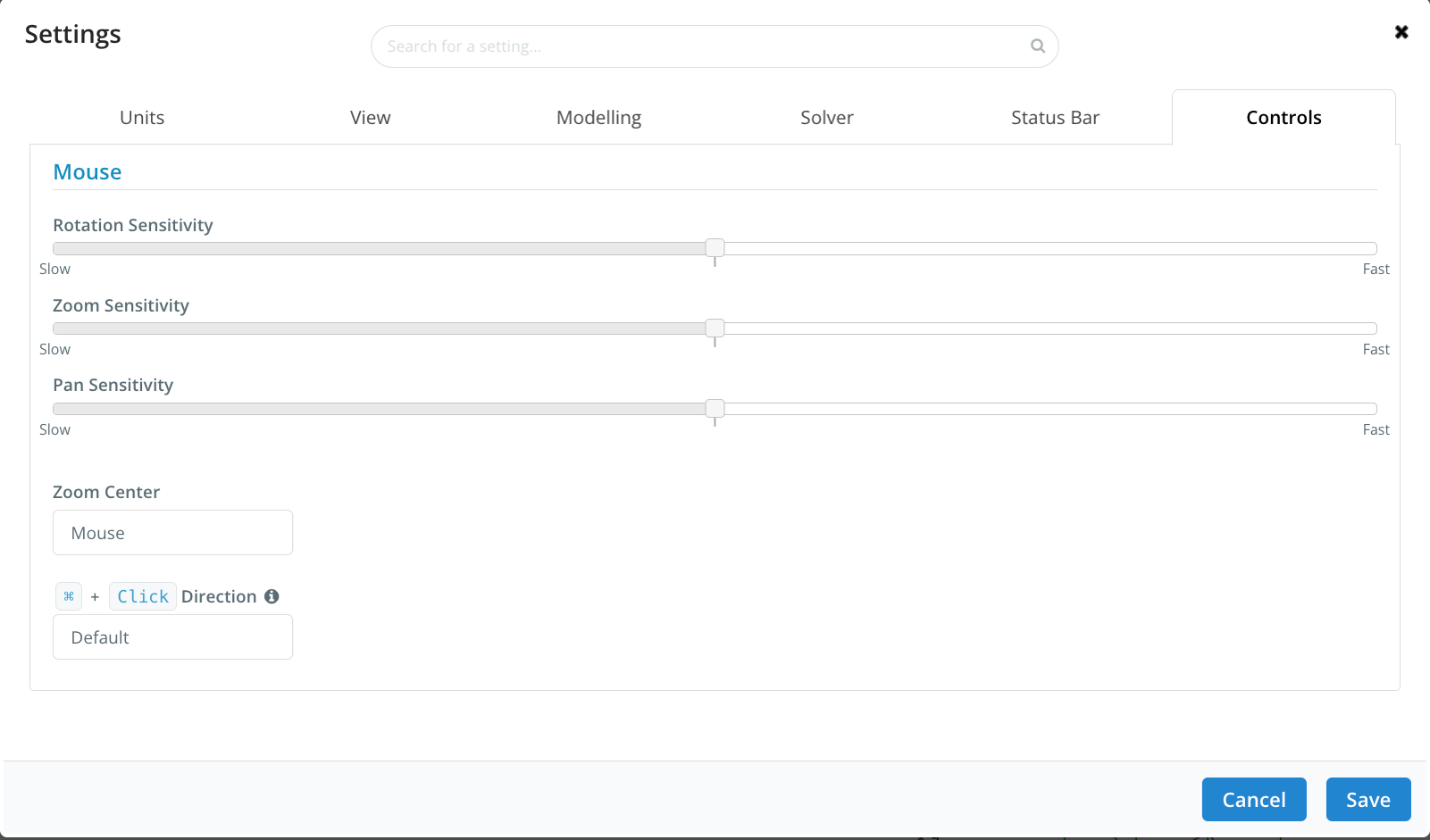
- Rotation Sensitivity, Zoom Sensitivity and Pan Sensitivity: Drag each slider between Slow and Fast.
- Zoom Center: Mouse zooms in and out where your cursor is. Center of Screen zooms on the center of the model space.
- Ctrl + Click Direction: With Default, dragging a selection box from left to right selects anything the box touches, and from right to left selects only what is fully inside the box. Reverse swaps the two. On Mac, the label shows ⌘ instead of Ctrl.
For all the mouse and keyboard controls, see Keyboard and Mouse Controls.
Visibility Settings
Visibility Settings control what is drawn on your structure. As a model grows (more members, plates and loads), the graphics get cluttered: use these options to show only what you need. Open them by clicking the eye icon in the toolbar on the right of the screen.
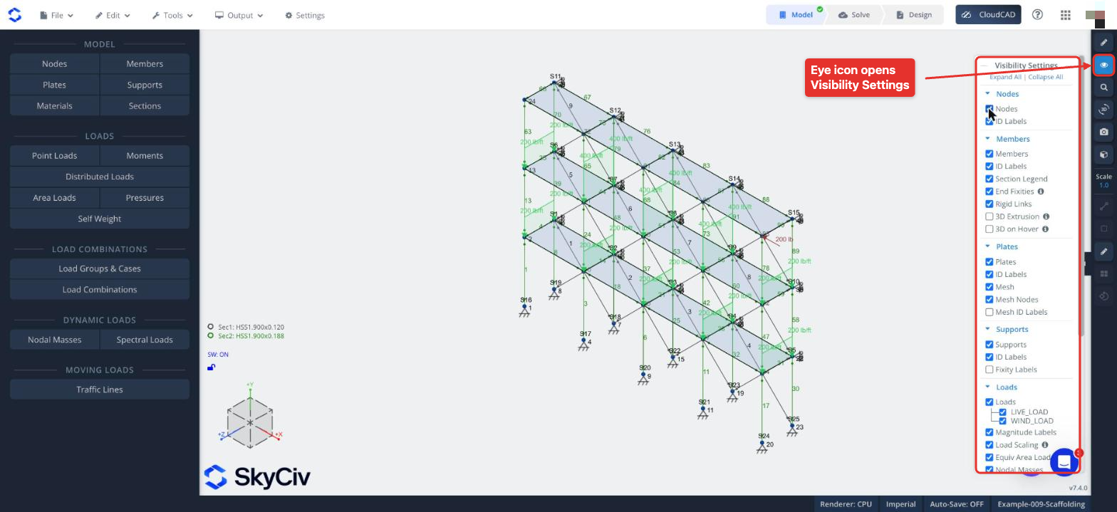
The options are grouped into sections. Click a section name to open or close it, or use Expand All and Collapse All at the top of the panel. Many options also have a keyboard shortcut, shown in brackets below: press it while working in the model (not while typing in an input box) to toggle the option without opening the panel.
Nodes
- Nodes (SHIFT+N): Show the nodes.
- ID Labels: Show the node IDs.
Members
- Members (SHIFT+M): Show the members.
- ID Labels: Show the member IDs.
- Section Legend: Show the legend of the sections, in the bottom left corner of the model space.
- End Fixities: Show the small dots at the ends of members that have a fixity other than FFFFFF (a release). Hover over a dot to see the fixity code.
- Rigid Links: Show rigid link members.
- 3D Extrusion (SHIFT+D): Show a simple extruded cross-section of every member.
- 3D on Hover: Show the extruded cross-section of a member when you hover over it.
Plates
- Plates (SHIFT+P): Show the plates.
- ID Labels: Show the plate IDs.
- Mesh (SHIFT+H): Show the plate meshes.
- Mesh Nodes (SHIFT+K): Show the nodes of the plate meshes.
- Mesh ID Labels: Show the IDs of the mesh elements.
Supports
- Supports (SHIFT+S): Show the supports.
- ID Labels: Show the support IDs.
- Fixity Labels: Show the fixity code of each support.
Loads
- Loads (SHIFT+L): Show the loads. Below it, tick or untick each load group to show or hide its loads.
- Magnitude Labels: Show the value of each load.
- Load Scaling: When on (the default), each load is drawn at a size proportional to its magnitude. When off, all loads are drawn at the same size.
- Equiv Area Loads (SHIFT+E): When on, show the equivalent distributed loads that the area loads apply to the members (these are the loads actually applied to the model), including the cantilevered areas of one-way area loads. When off, area loads are drawn as pressure boxes.
- Nodal Masses: Show the nodal masses.
- Color By: Color the loads by Default (by load type), Group or Case. SHIFT+C toggles the load coloring by load case.
Axis Helpers
- Global Origin Axes: Show the global axes at the origin (0, 0, 0).
- Local Axes (SHIFT+X): Show the local axes of members and plates, to check their orientation in 3D space.
- Mesh Local Axes: Show the local axes of the meshed plate elements.
- Nodal Global Axes: Show global axis helpers at each node and support.
Offsets
- Offset Elements: Draw members and plates at their offset position. This only changes the graphics: offsets are always used by the solver.
- Visual Links: Draw a line from the original node to the offset position of members and plates.
Other
- Faint Structure: Grey out the whole structure, which is useful when you look at solver results.
- Gridlines & Elevations (SHIFT+G): Show the gridlines and elevations.
On large models, a Smart Labels option can appear at the top of the panel. It declutters the screen by showing labels only when you zoom in, and the label options are disabled while it is on.
Click My Views at the bottom of the panel (or press SHIFT+V) to save the current view of your model and return to it at any time. To show again all the elements you have hidden with Hide Selected (Ctrl + H) or Isolate (Ctrl + I), press SHIFT+A (Show All).
You can change or remove these shortcuts in the Shortcuts tab of the Operations Toolbox.
