
Qu'est-ce qu'une connexion momentanée?
Une connexion momentanée est une articulation qui transfère moments de flexion entre un poteau et une poutre, ou entre deux membres. Si une poutre porte un moment interne à son extrémité, la connexion doit transmettre ce moment à travers le joint plutôt que de laisser l'extrémité tourner librement.
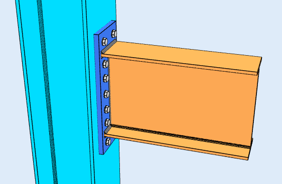
Connexion de plaque d'extrémité étendue, un exemple de connexion momentanée. Les boulons à l'extérieur de la bride de tension donnent au couple un bras de levier plus long.
Le but d'un connexion moment est de maintenir la rotation finale, qui, en termes d'analyse, est le code de fixité FFFFFF: retenu dans les trois traductions et les trois rotations. C'est pourquoi les connexions par moment sont également appelées connexions rigides..
AISC 360-16 La section B3.4 est plus précise à ce sujet, et la distinction compte lorsque vous modélisez le cadre. Une connexion momentanée est soit entièrement retenu (FR), qui maintient l'angle entre les membres et justifie l'hypothèse FFFFFF, ou partiellement retenu (RP), qui transfère le moment mais tourne suffisamment pour que l'analyse doive tenir compte de la rigidité réelle de l'assemblage. Traiter un joint PR comme entièrement rigide surestime la rigidité du cadre et sous-estime sa dérive..
Où un connexion de cisaillement fonctionne principalement à travers l'âme de la poutre, un moment de connexion doit s'engager dans les brides, parce que c'est là que se situe la contrainte de flexion. Plaques à bride, des brides soudées ou une plaque d'extrémité font tous le même travail: ils transforment le moment de la poutre en une force de tension dans une semelle et une force de compression dans l'autre, et emmène ce couple dans la colonne.
Types de connexion Moment
Les connexions de moment transportent beaucoup plus de moment qu'une connexion de cisaillement, et ils coûtent plus cher à fabriquer: plus de matériel, plus de soudure, plus d'aménagement et plus d'inspection. La plupart des cadres les utilisent uniquement lorsque la structure repose sur l'action du cadre pour la stabilité latérale., et utilisez des connexions de cisaillement partout ailleurs.
Les configurations disponibles dépendent du code de conception et de la composition des poutres..
Poutre vers poteau en I (AISC 360-16)
Quatre configurations, charpente à la semelle du poteau ou à l'âme du poteau.
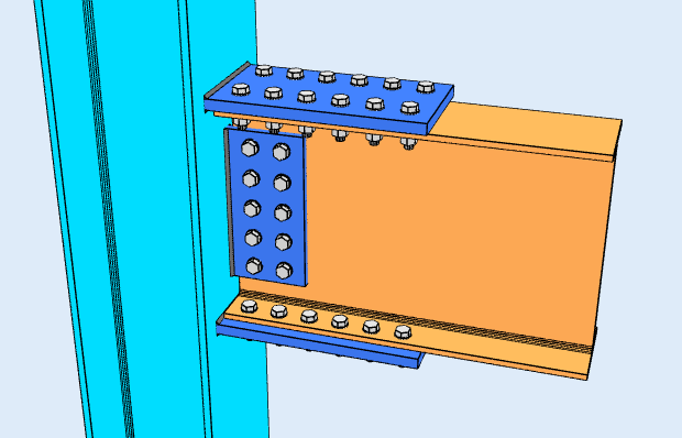
Plaque de bride
Les plaques traversent les ailes supérieure et inférieure de la poutre, boulonné ou soudé à la poutre et au poteau. Alors que la poutre se plie, une plaque passe en tension et l'autre en compression, et ce couple porte le moment. L'âme de la poutre est généralement portée par une plaque de cisaillement séparée, donc la connexion divise le travail: les brides prennent le moment, le web prend le dessus.
Brides soudées
Les ailes de la poutre sont soudées directement à l'aile du poteau., sans plaque intermédiaire, et l'âme est boulonnée à une languette de cisaillement. Cela donne le joint le plus rigide du groupe et le chemin de charge le plus propre, mais il s'agit d'un soudage sur site sur un élément qui doit s'adapter à la tolérance, donc il transporte le préchauffage, des coûts d'accès et d'inspection qu'un détail boulonné ne représente pas.
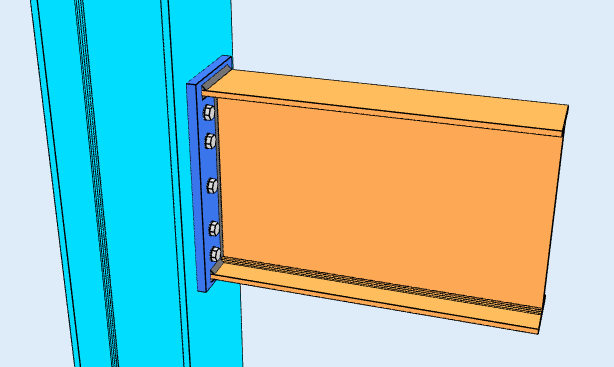
Plaque d'extrémité affleurante
Une plaque soudée à l'extrémité de la poutre et boulonnée au poteau, avec la plaque finissant au ras des ailes de la poutre et tous les boulons placés entre elles. Cela convient aux moments inférieurs, parce que le bras de levier du groupe de boulons est limité par la profondeur de la poutre.
Plaque d'extrémité étendue
La même idée, avec la plaque dépassant de la bride de tension afin que les boulons puissent reposer à l'extérieur. Ces boulons extérieurs ont un bras de levier plus long autour de la bride de compression, c'est ce qui achète la capacité de moment supplémentaire. L'action de levier sur la partie étendue devient un contrôle déterminant. C'est la configuration affichée en haut de cette page.
Les deux configurations de plaque d'extrémité sont couvertes par le calculateur de connexion moment.
Poutre vers colonne HSS (AISC 360-16)
Encadrer un assemblage de moment dans une section creuse est plus difficile, car il n'y a pas de bride à boulonner et pas d'accès au côté éloigné. Une configuration est disponible: a plaque de bride soudé à la face du HSS, sans raidisseurs.
AS 4100:2020
AS 4100 la couverture dans SkyCiv Connection Design est uniquement des connexions de cisaillement, poutre de charpente sur poteau en I ou poutre sur poutre. Connexions momentanées à AS 4100 ne sont pas disponibles. Pour le design momentané, utiliser l'AISC 360-16.
Que vérifie le logiciel?
Les détails s'exécutent en premier: distances entre les bords des boulons, espacement des boulons (pas et jauge), jeux d'outils, dimensions minimales et maximales de la plaque, et détection de collision entre plaques, raidisseurs, boulons et soudures. Une connexion qui ne peut pas être établie n’atteint pas la solution.
Les contrôles de force suivent ensuite le couple à travers l'articulation. Côté bride cela signifie la plaque en traction et en compression, cisaillement des boulons, roulement de boulon et arrachement, rupture par cisaillement du bloc, action de levier sur les boulons, et contrainte de la gorge de soudure. Sur l'élément de support, cela signifie une flexion locale de la bride, Web local productif et Web paralysant, quels sont les états limites qui décident si le poteau a besoin de raidisseurs ou d'une plaque doubleur.
Chaque formule, le contrôle de conception et la référence du code sont affichés dans leur intégralité, avec les numéros de clause de l'AISC 360-16, pour que vous puissiez suivre le calcul plutôt que de vous y fier.
Connexion de moment vs connexion de cisaillement: la différence
La différence est ce qui arrive à l'angle entre les deux membres. Dans un moment de connexion, cet angle est maintenu, donc la flexion d'un membre se répercute sur l'autre. Dans un assemblage par cisaillement, l'assemblage est libre de tourner, de sorte que l'extrémité de la poutre tourne et qu'aucun moment significatif ne traverse le joint.
| Connexion rigide | Connexion rotulé | |
|---|---|---|
| Forces transférées | Cisaillement et moment | Cisaillement seulement |
| Noms alternatifs | Rigide, Fixé, Résistant aux moments | Épinglé, Charnière, Facile |
| AISC 360-16 terme | Connexion instantanée FR ou PR | Connexion simple |
| Rotation | Restreint la rotation | Libre de tourner |
| Code de fixité du logiciel | FFFFFF | FFFFFR |
Logiciel de conception de connexion SkyCiv
Les modèles et chèques ci-dessus proviennent de Conception de connexion SkyCiv. Il couvre 80+ types de connexion préconfigurés, des dessins pour AISC 360-16 en LRFD et ASD et à AS 4100:2020, et montre chaque formule, vérification de la conception et référence du code dans son intégralité.
Vous pouvez modéliser la connexion en 3D, échanger les boulons, soudures ou plaques sans perdre vos données de charge, produire des feuilles de dessin de détail 2D dans CloudCAD, et exporter la géométrie 3D vers IFC pour coordination dans Revit, Tekla ou Navisworks.
Il fonctionne entièrement dans le navigateur, sans téléchargement, mises à jour ou configuration informatique.
