
Extended end plate moment connection design to AISC 360 et Guide de conception AISC 39 comes down to the same three things as any end plate: bolts big enough to carry the flange tension without prying, an end plate thick enough to stay stiff around those bolts, and welds and a column that can deliver the force on both sides. The extended plate adds a bolt row outside the tension flange, which gives the bolts a longer lever arm and the plate more yield lines, so it carries much larger moments than a flush plate.
This page works through one real extended end plate moment connection from start to finish: a W21x166 beam bolted to the flange of a W14x193 column through a 7/8 in end plate with 3/4 in A325-N bolts, carrying a 300 kip-ft moment, a 120 kip shear and 200 kip of axial tension or compression. It is designed to AISC 360-16 LRFD, the AISC Manual 15th Edition and Design Guide 39. Chaque équation est écrite avec ses chiffres, dans le même ordre que la feuille de calcul AISC, le Conception de connexion SkyCiv le module produit pour cela.
What is an extended end plate moment connection?
An end plate moment connection is a plate welded to the end of a beam in the shop and bolted to the column on site. In an extended end plate, the plate projects past the beam flanges and carries a row of bolts outside them. In a flush end plate, the plate stops at the flanges and every bolt sits between them. The outside row is the furthest bolt from the compression flange, so it does the most work, and the extension adds yield lines that make the plate stronger in bending.
It is a connexion moment: the welds and bolts are designed so the joint transfers the full beam moment into the column, rather than letting the beam end rotate. Both the flush and extended versions are covered by the end plate connection calculator, et la connexions moment page compares them with the flange plate moment connection and other details.
The plate in this example extends past both flanges, so the connection works the same way if the moment reverses. Its bolt pattern is the Design Guide 39 multiple-row extended 1/3 four-wide/two-wide configuration: one row outside each flange and three inside, with four bolts across the outside row and the first inside row, and two across the rest.
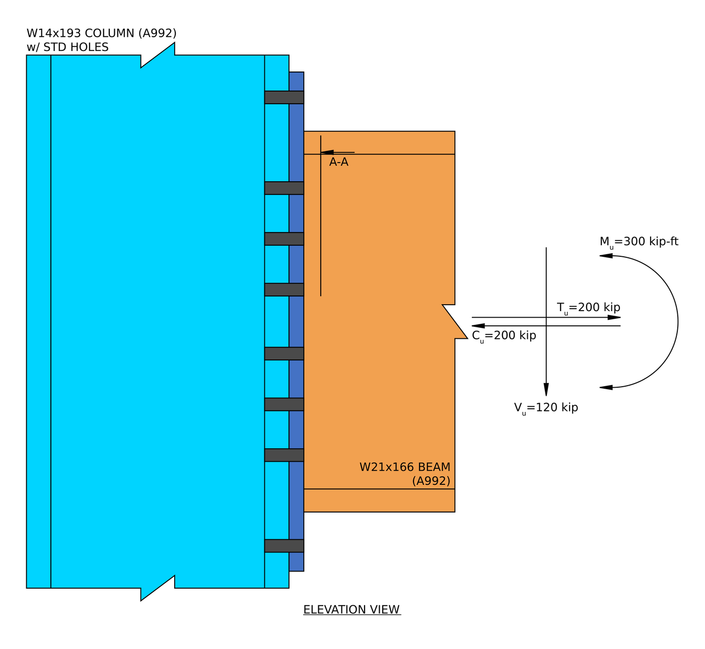
l'élévation. The end plate extends past both flanges of the W21x166 and is bolted to the W14x193 column flange with eight bolt rows.
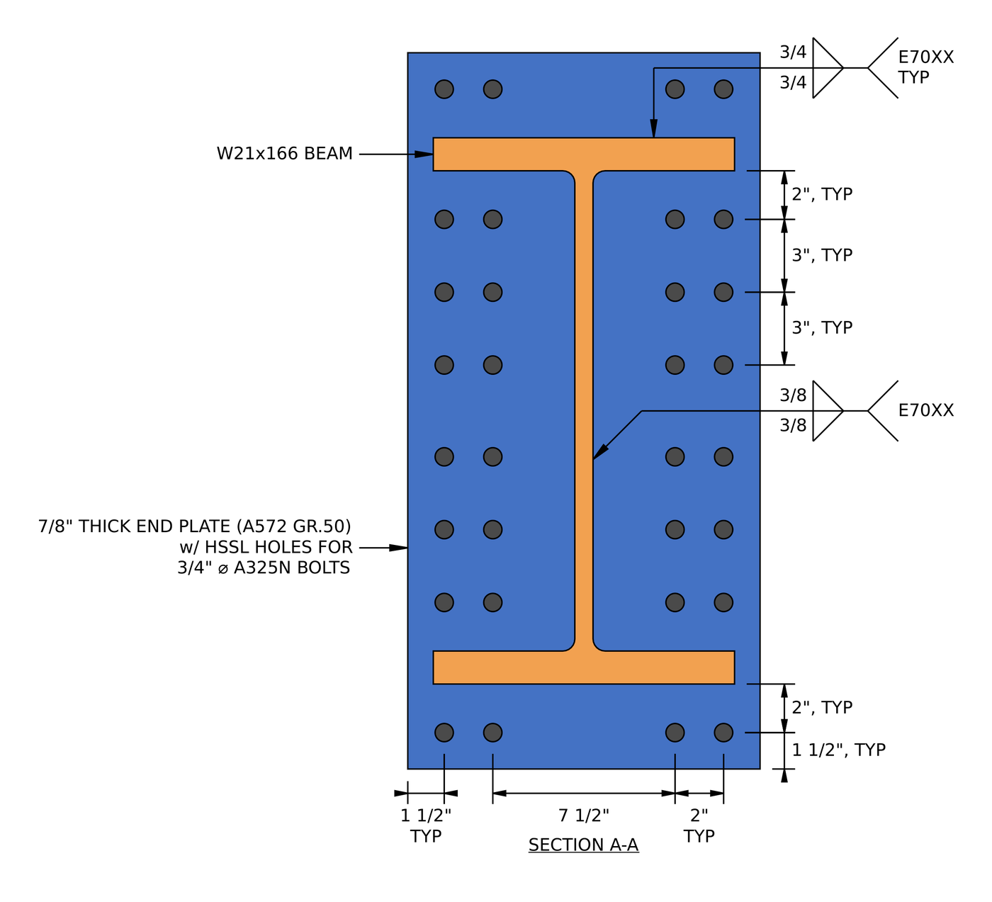
Section A-A. One bolt row outside each flange and three inside, 2 in from the flange faces and 3 in apart. Each row is four bolts wide: a 7 1/2 in gage with a 2 in column spacing outside it.
Extended end plate moment connection design: the steps at a glance
The design follows AISC Design Guide 39: size the bolts and the plate for the moment first, then check the extension, the welds, the bolts in shear and the column.
- Check the detailing limits for the welds, bolts and plate.
- Find the equivalent moment and the required bolt diameter.
- Find the yield line parameter and the required end plate thickness.
- Check the extended portion of the end plate in shear.
- Check the fillet welds at the beam flange.
- Check the beam flange base metal at the weld.
- Check the fillet welds at the beam web for tension.
- Check the beam web base metal at the weld.
- Check the fillet welds at the beam web for shear.
- Check the bolts in shear.
- Check bolt bearing and tear-out on the end plate.
- Check bolt bearing and tear-out on the column flange.
- Check column flange bending at the tension bolts.
- Check the column under the compression flange force.
Entrées de conception pour cet exemple
Le code de conception est AISC 360-16 LRFD, with the end plate procedure from AISC Design Guide 39. Les propriétés de la section proviennent du manuel AISC.
| Charge | Symbole | Valeur |
|---|---|---|
| Cisaillement vertical pondéré | [mathin] V_{u} [mathin] | 120 kip |
| Factored axial tension | [mathin] T_{u} [mathin] | 200 kip |
| Factored axial compression | [mathin] C_{u} [mathin] | 200 kip |
| Factored strong-axis moment | [mathin] M_{ux} [mathin] | 300 kip-ft |
| Member property | Symbole | Beam | Colonne |
|---|---|---|---|
| Section | W21x166, A992 | W14x193, A992 | |
| Profondeur | [mathin] d_{bm},\ d_{sup} [mathin] | 22.5 in | 15.5 in |
| Épaisseur de l'âme | [mathin] t_{wb},\ t_{ws} [mathin] | 0.75 in | 0.89 in |
| Flange width | [mathin] b_{fb},\ b_{fs} [mathin] | 12.4 in | 15.7 in |
| Flange thickness | [mathin] t_{fb},\ t_{fs} [mathin] | 1.36 in | 1.44 in |
| l'aire | [mathin] A [mathin] | 48.8 in² | 56.8 in² |
| Rendement / contrainte de traction | [mathin] F_{y},\ F_{u} [mathin] | 50 KSI / 65 KSI | 50 KSI / 65 KSI |
| Module d'élasticité | [mathin] E [mathin] | 29000 KSI | 29000 KSI |
| Plaque d'extrémité, boulons et soudures | Symbole | Valeur |
|---|---|---|
| End plate width / profondeur / thickness | [mathin] b_{p},\ d_{p},\ t_{p} [mathin] | 14.5 in / 29.5 in / 0.875 in, A572 Gr. 50 |
| Rendement des plaques / contrainte de traction | [mathin] F_{yp},\ F_{up} [mathin] | 50 KSI / 65 KSI |
| Boulons | [mathin] d_{b} [mathin] | 3/4 in A325-N, one shear plane |
| Traction nominale du boulon / contrainte de cisaillement | [mathin] F_{nt},\ F_{nv} [mathin] | 90 KSI / 54 KSI |
| Holes in end plate / bride de colonne | Horizontal à fente courte (CSSS) / nommée (MST) | |
| Bolt rows between the flanges / outside each flange | [mathin] n_{r},\ n_{ro} [mathin] | 6 / 1 |
| Bolt row spacing | [mathin] s_{r} [mathin] | 3 in |
| Colonnes de boulons / outside the beam flange | [mathin] n_{c},\ n_{co} [mathin] | 4 / 4 |
| Bolt gage / espacement des colonnes | [mathin] g,\ s_{c} [mathin] | 7.5 in / 2 in |
| Bolt flange offset (flange face to nearest row, inside and outside) | [mathin] p_{f} [mathin] | 2 in |
| Fillet weld at beam flanges | [mathin] W_{1} [mathin] | 0.75 in (3/4 in), E70XX |
| Fillet weld at beam web | [mathin] W_{2} [mathin] | 0.375 in (3/8 in), E70XX |
Étape 1: Detailing limits (AISC 360-16 J2.2b, J3.3, J3.4, J3.5)
Avant tout contrôle de solidité, the connection has to be buildable and match the assumptions behind the Design Guide 39 équations. The welds must be at least the minimum size for the parts they join, and the bolts must be far enough apart and far enough from the edges.
The minimum fillet weld sizes come from Table J2.4: 5/16 in for the flanges, where the thinner part joined is the 7/8 en assiette, et 1/4 in for the 3/4 in web. L'espacement minimum des boulons est [mathin] 2\tfrac{2}{3} d_{b} [mathin] à partir de J3.3, lequel est 2 in for a 3/4 in bolt, and it applies both between rows and between columns. The edge distances come from Table J3.4. The end plate has horizontal short slots, so Table J3.5 adds 1/8 in to its horizontal edge distance, donner 1.125 in. The maximum gage on the end plate is the beam flange width, 12.4 in.
| Limite de détail | Limite (in) | Réel (in) | DCR | Résultat |
|---|---|---|---|---|
| Minimum weld size at flanges | 0.313 | 0.750 | 0.417 | cdot K_a |
| Minimum weld size at web | 0.250 | 0.375 | 0.667 | cdot K_a |
| Espacement minimum des rangées de boulons | 2.000 | 3.000 | 0.667 | cdot K_a |
| Espacement maximal des rangées de boulons | 6.000 | 3.000 | 0.500 | cdot K_a |
| Minimum bolt column spacing | 2.000 | 2.000 | 1.000 | cdot K_a |
| Maximum bolt column spacing | 6.000 | 2.000 | 0.333 | cdot K_a |
| End plate minimum vertical edge distance | 1.000 | 1.500 | 0.667 | cdot K_a |
| End plate minimum horizontal edge distance | 1.125 | 1.500 | 0.750 | cdot K_a |
| Support minimum horizontal edge distance | 1.000 | 2.100 | 0.476 | cdot K_a |
| Minimum bolt gage at support | 4.875 | 7.500 | 0.650 | cdot K_a |
| Minimum bolt gage at end plate | 3.000 | 7.500 | 0.400 | cdot K_a |
| Maximum bolt gage at end plate | 12.400 | 7.500 | 0.605 | cdot K_a |
| Minimum bolt flange offset | 1.500 | 2.000 | 0.750 | cdot K_a |
Pour une limite minimale, le rapport est la limite sur la valeur réelle, et pour un maximum, c'est un dépassement réel de la limite. The governing row is the bolt column spacing:
[math] DCR = \frac{d}{c} = \frac{(2)}{(2)} = 1 [math]
DCR = 1.000 ≤ 1.0, d'accord
Ce logiciel 2 in column spacing sits exactly on the J3.3 minimum. That passes, but J3.3 prefers a spacing of 3d, so there is no room left for a larger bolt in this pattern without widening it. Ce logiciel 2.1 in support edge distance is what is left of the 15.7 in column flange outside the outer bolts.
Étape 2: Required bolt diameter (Guide de conception AISC 39, Eq. 3-30 and 5-3a)
The bolts near the tension flange carry the moment as tension. Guide de conception 39 sizes them so they reach their tensile strength without any prying force, which is only possible if the end plate is then made thick enough to stay stiff (Étape 3).
Equivalent moment with axial tension
Axial tension pulls on the tension bolts as well. The guide adds it to the moment as half the tension acting over the distance between the flange centroids:
[math] M_{u,eq} = M_{ux} + \frac{T_{u}}{2} \left( d_{bm} – t_{fb} \right) [math]
[math] M_{u,eq} = (300\,kip\text{-}ft) + \frac{(200\,kip)}{2} \times \left( (22.5\,in) – (1.36\,in) \right) = 476.17\,kip\text{-}ft [math]
Bolt lever arms
The tension bolts rotate about the centre of the compression flange. The four tension rows sit at these distances from it:
- [mathin] h_{1} = 23.82\,in [mathin]: the row outside the tension flange, 2 in past its outside face
- [mathin] h_{2} = 18.46\,in [mathin]: the first row inside, 2 in from the inside face of the flange
- [mathin] h_{3} = 15.46\,in [mathin] et [mathin] h_{4} = 12.46\,in [mathin]: the next two rows, 3 in apart
In the four-wide/two-wide pattern, the two rows nearest the tension flange count four bolts each and the other two count only the two bolts at the 7.5 in gage, lequel est 12 tension bolts in all. The outer bolts of rows 3 et 4 are too far from both the flange and the web to pick up much tension, so Design Guide 39 leaves them out:
[math] \sum_{i} n_{i} h_{i} = 4 \left( h_{1} + h_{2} \right) + 2 \left( h_{3} + h_{4} \right) = 224.96\,in [math]
Required bolt diameter
Où [mathin] \phi = 0.75 [mathin] is the resistance factor for bolt tension and [mathin] F_{nt} = 90\,ksi [mathin] is the nominal tensile stress of an A325 bolt:
[math] d_{b,reqd} = \sqrt{\frac{4\, M_{u,eq}}{\pi\, \phi\, F_{nt} \sum_{i} n_{i} h_{i}}} [math]
[math] d_{b,reqd} = \sqrt{\frac{4 \times (476.17\,kip\text{-}ft)}{\pi \times (0.75) \times (90\,ksi) \times (224.96\,in)}} [math]
[math] d_{b,reqd} = 0.69218\,in [math]
[math] DCR = \frac{d_{b,reqd}}{d_{b}} = \frac{(0.69218\,in)}{(0.75\,in)} = 0.92291 [math]
DCR = 0.923 < 1.0, d'accord
The axial tension adds 176.17 kip-ft to the 300 kip-ft moment, so the axial load drives a large share of the bolt size.
Étape 3: Required end plate thickness (Guide de conception AISC 39, Le tableau 5-17 et éq. 5-5a)
The end plate bends around the tension bolts. Guide de conception 39 finds its strength from a yield line pattern: the set of hinge lines that form in the plate when it fails. The plate is then made thick enough that it stays elastic, so the bolts see no prying.
Effective plate width and yield line pitch
Plate wider than the beam flange does little to resist the yield lines, so the guide limits the width it counts to the flange width plus the larger of 1 in and the plate thickness:
[math] b_{pe} = \min\left( b_{p},\, b_{fb} + \max\left( 1\,in,\, t_{p} \right) \right) = \min\left( (14.5\,in),\, (12.4\,in) + \max\left( (1\,in),\, (0.875\,in) \right) \right) = 13.4\,in [math]
The yield line pitch s locates the hinge lines below the inside bolts. The report calculates it from the full plate width:
[math] s = \frac{\sqrt{b_{p}\, g}}{2} = \frac{\sqrt{(14.5\,in)(7.5\,in)}}{2} = 5.2142\,in [math]
Yield line parameter
For the 12-bolt multiple-row extended 1/3 four-wide/two-wide unstiffened end plate, Le tableau 5-17 gives:
[math] Y_{p} = \frac{b_{pe}}{2} \left( \frac{h_{1}}{p_{fo}} + \frac{h_{2}}{p_{fi}} + \frac{h_{4}}{s} – \frac{1}{2} \right) + \frac{2}{g} \left( h_{2} \left( p_{fi} + \frac{3 s_{r}}{2} \right) + h_{4} \left( s + \frac{s_{r}}{2} \right) \right) + \frac{g}{2} [math]
Avec [mathin] b_{pe} = 13.4\,in [mathin], [mathin] g = 7.5\,in [mathin], [mathin] h_{1} = 23.82\,in [mathin], [mathin] h_{2} = 18.46\,in [mathin], [mathin] h_{4} = 12.46\,in [mathin], [mathin] p_{fi} = p_{fo} = 2\,in [mathin], [mathin] s = 5.2142\,in [mathin] et [mathin] s_{r} = 3\,in [mathin]:
[math] Y_{p} = 212.35\,in [math]
A flush plate’s yield line pattern only has the tension rows between the flanges. Here the extension adds the outside row and its yield lines, and that is where the extra strength of an extended plate comes from.
Required plate thickness
Où [mathin] \gamma_{r} = 1 [mathin] is the Design Guide 39 Eq. 5-1 factor for full restraint (an extended plate needs no reduction, unlike the 0.8 used for flush plates), [mathin] \phi = 0.9 [mathin] is the resistance factor for flexure and [mathin] F_{yp} = 50\,ksi [mathin]:
[math] t_{p,reqd} = \sqrt{\frac{1.10\, M_{u,eq}}{\gamma_{r}\, \phi\, F_{yp}\, Y_{p}}} [math]
[math] t_{p,reqd} = \sqrt{\frac{1.10 \times (476.17\,kip\text{-}ft)}{(1) \times (0.9) \times (50\,ksi) \times (212.35\,in)}} [math]
[math] t_{p,reqd} = 0.81102\,in [math]
[math] DCR = \frac{t_{p,reqd}}{t_{p}} = \frac{(0.81102\,in)}{(0.875\,in)} = 0.92687 [math]
DCR = 0.927 < 1.0, d'accord
Ce logiciel 1.10 factor keeps the plate’s yield line strength 10% above the demand, so the plate stays stiff and the no-prying assumption in Step 2 holds.
Étape 4: Shear yielding and rupture of the extended portion of the end plate (AISC 360-16 J4.2)
The bolts outside the tension flange pull on the part of the plate that sticks out past the flange. That force has to cross into the flange as shear through the plate, along a horizontal line at the face of the flange.
Shear on the extension
The outside bolts take their share of the flange force: [mathin] n_{to} = 4 [mathin] de la [mathin] n_{t} = 12 [mathin] tension bolts.
[math] V_{ep} = \frac{n_{to}}{n_{t}} \left( \frac{M_{ux}}{d_{bm} – t_{fb}} + \frac{T_{u}}{2} \right) [math]
[math] V_{ep} = \frac{(4)}{(12)} \left( \frac{(300\,kip\text{-}ft)}{(22.5\,in) – (1.36\,in)} + \frac{(200\,kip)}{2} \right) = 90.098\,kip [math]
Cédant au cisaillement (Eq. J4-3)
The gross shear area is the full plate width times its thickness, et [mathin] \phi = 1.00 [mathin] for shear yielding:
[math] A_{gv} = b_{p}\, t_{p} = (14.5\,in) \times (0.875\,in) = 12.688\,in^{2} [math]
[math] \phi R_{n,sy} = \phi\, 0.6\, F_{yp}\, A_{gv} = (1) \times 0.6 \times (50\,ksi) \times (12.688\,in^{2}) = 380.62\,kip [math]
Rupture par cisaillement (Eq. J4-4)
The net area takes out the four bolt holes in the outside row. The shear line runs horizontally, so it cuts each slot along its 1 in length, plus the 1/16 in AISC adds for hole damage (B4.3b):
[math] A_{nv} = t_{p} \left[ b_{p} – n_{co} \left( d_{h} + 0.0625\,in \right) \right] = (0.875\,in) \times \left[ (14.5\,in) – (4) \times \left( (1\,in) + (0.0625\,in) \right) \right] = 8.9687\,in^{2} [math]
[math] \phi R_{n,sr} = \phi\, 0.6\, F_{up}\, A_{nv} = (0.75) \times 0.6 \times (65\,ksi) \times (8.9687\,in^{2}) = 262.34\,kip [math]
Governing strength
[math] \phi R_{n} = \min\left( \phi R_{n,sy},\, \phi R_{n,sr} \right) = \min\left( (380.62\,kip),\, (262.34\,kip) \right) = 262.34\,kip [math]
[math] DCR = \frac{V_{ep}}{\phi R_{n}} = \frac{(90.098\,kip)}{(262.34\,kip)} = 0.34344 [math]
DCR = 0.343 < 1.0, d'accord
Rupture governs because four slots come out of a single line across the plate. The extension still has plenty of reserve.
Étape 5: Fillet weld at the beam flange (Guide de conception AISC 39 Eq. 3-38a, AISC 360-16 J2.4)
The flange welds carry the flange force from the beam into the end plate. They are fillet welds on both faces of the flange, loaded perpendicular to their length.
Effective weld length
The outside weld runs the full width of the flange. The inside weld stops short of the web on each side, by the distance [mathin] k_{1} = 1.5625\,in [mathin] from the web centreline to the toe of the flange fillet:
[math] L_{w} = 2 \left( \min\left( b_{fb},\, b_{p} \right) \right) – 2 k_{1} [math]
[math] L_{w} = 2 \left( \min\left( (12.4\,in),\, (14.5\,in) \right) \right) – 2 (1.5625\,in) = 21.675\,in [math]
Flange force
The flange force is the moment divided by the distance between flange centroids, plus half the larger axial load. Guide de conception 39 also sets a floor of 60% of the flange’s yield strength, so the welds are never the weak link even when the moment is small:
[math] P_{fl} = \max\left( \frac{M_{ux}}{d_{bm} – t_{fb}} + \frac{\max\left( T_{u},\, C_{u} \right)}{2},\, 0.6\, F_{yb}\, b_{fb}\, t_{fb} \right) [math]
[math] P_{fl} = \max\left( \frac{(300\,kip\text{-}ft)}{(22.5\,in) – (1.36\,in)} + \frac{\max\left( (200\,kip),\, (200\,kip) \right)}{2},\, 0.6\,(50\,ksi)\,(12.4\,in)\,(1.36\,in) \right) [math]
[math] P_{fl} = 505.92\,kip [math]
The moment and axial load give 270.29 kip (the same force Step 14 uses for the column), alors le 60% floor governs. With a flange as heavy as the W21x166’s, the welds end up sized for the flange, not the load.
Force de soudure
Où [mathin] F_{EXX} = 70\,ksi [mathin], [mathin] W_{1} = 0.75\,in [mathin], [mathin] \phi = 0.75 [mathin], and the factor 1.5 is the J2.4 directional strength increase for a weld loaded perpendicular to its axis:
[math] \phi R_{n} = \phi\, 0.6\, F_{EXX} \left( \frac{\sqrt{2}}{2} W_{1} \right) L_{w}\, 1.5 [math]
[math] \phi R_{n} = (0.75)\, 0.6\, (70\,ksi) \left( \frac{\sqrt{2}}{2} (0.75\,in) \right) (21.675\,in)\, 1.5 [math]
[math] \phi R_{n} = 543.13\,kip [math]
[math] DCR = \frac{P_{fl}}{\phi R_{n}} = \frac{(505.92\,kip)}{(543.13\,kip)} = 0.93148 [math]
DCR = 0.931 < 1.0, d'accord
This is the highest strength ratio in the connection. It is driven by the 60% étage, not the applied load.
Étape 6: Beam flange base metal at the weld (AISC 360-16 J4.1)
The flange metal next to the weld has to carry the same force. It is checked as a tension element, yielding and rupture, over the length of one weld line, because the welds on both faces of the flange load the same piece of flange.
Avec [mathin] 0.5 L_{w} = 10.837\,in [mathin] for one weld line:
[math] \phi R_{n,ty} = \phi\, F_{yb}\, t_{fb}\, 0.5 L_{w} = (0.9) \times (50\,ksi) \times (1.36\,in) \times (10.837\,in) = 663.25\,kip [math]
[math] \phi R_{n,tr} = \phi\, F_{ub}\, t_{fb}\, 0.5 L_{w} = (0.75) \times (65\,ksi) \times (1.36\,in) \times (10.837\,in) = 718.53\,kip [math]
[math] \phi R_{n} = \min\left( \phi R_{n,ty},\, \phi R_{n,tr} \right) = \min\left( (663.25\,kip),\, (718.53\,kip) \right) = 663.25\,kip [math]
[math] DCR = \frac{P_{fl}}{\phi R_{n}} = \frac{(505.92\,kip)}{(663.25\,kip)} = 0.76278 [math]
DCR = 0.763 < 1.0, d'accord
Étape 7: Fillet weld at the beam web in tension (Guide de conception AISC 39 Fig. 3-17, Eq. 3-39 to 3-41a)
The inside tension bolts sit close to the beam web, so part of their force goes into the web rather than the flange. The web welds near those bolts have to carry that force into the end plate.
Effective weld length in tension
Only the web weld near the tension bolts counts: from the end of the flange fillet down past the last inside tension row plus 6 in, but no further than mid-depth. Avec [mathin] k_{det} = 2.625\,in [mathin] et [mathin] n_{ti} = 3 [mathin] inside bolt rows in tension:
[math] L_{wt} = 2 \left( \min\left( p_{f} – \left( k_{det} – t_{fb} \right) + s_{r} \left( n_{ti} – 1 \right) + 6\,in,\, 0.5\, d_{bm} – k_{det} \right) \right) [math]
[math] L_{wt} = 2 \left( \min\left( (2\,in) – \left( (2.625\,in) – (1.36\,in) \right) + (3\,in)\left( (4) – 1 \right) + 6\,(1\,in),\, 0.5\,(22.5\,in) – (2.625\,in) \right) \right) [math]
[math] L_{wt} = 17.25\,in [math]
The substituted line prints 4 rows where the inputs list 3. The result is set by the mid-depth limit, the second term, which does not depend on the row count.
Force on the web weld
Du [mathin] n_{t} = 12 [mathin] tension bolts, [mathin] n_{trib} = 6 [mathin] sit next to the web: the inner pair in each of the three inside rows. The outside row is beyond the flange, so it loads the flange rather than the web. There is again a floor, ici 60% of the yield strength of the web over the weld length:
[math] P_{w} = \max\left( \frac{n_{trib}}{n_{t}} \left( \frac{M_{ux}}{d_{bm} – t_{fb}} + \frac{T_{u}}{2} \right),\, 0.6\, F_{yb} \left( 0.5 L_{wt} \right) t_{wb} \right) [math]
[math] P_{w} = \max\left( \frac{(6)}{(12)} \left( \frac{(300\,kip\text{-}ft)}{(22.5\,in) – (1.36\,in)} + \frac{(200\,kip)}{2} \right),\, 0.6\,(50\,ksi)\,(0.5\,(17.25\,in))\,(0.75\,in) \right) [math]
[math] P_{w} = 194.06\,kip [math]
Half of the 270.29 kip flange force is less than 194.06 kip, so the floor governs here too.
Force de soudure
[math] \phi R_{n} = \phi\, 0.6\, F_{EXX} \left( \frac{\sqrt{2}}{2} W_{2} \right) L_{wt}\, 1.5 [math]
[math] \phi R_{n} = (0.75)\, 0.6\, (70\,ksi) \left( \frac{\sqrt{2}}{2} (0.375\,in) \right) (17.25\,in)\, 1.5 = 216.13\,kip [math]
[math] DCR = \frac{P_{w}}{\phi R_{n}} = \frac{(194.06\,kip)}{(216.13\,kip)} = 0.89791 [math]
DCR = 0.898 < 1.0, d'accord
Étape 8: Beam web base metal at the weld (AISC 360-16 J4.1)
The web next to the tension weld has to carry the same 194.06 kip without yielding or rupturing. As with the flange, the length is one weld line, [mathin] 0.5 L_{w} = 8.625\,in [mathin].
[math] \phi R_{n,ty} = \phi\, F_{yb}\, t_{wb}\, 0.5 L_{w} = (0.9) \times (50\,ksi) \times (0.75\,in) \times (8.625\,in) = 291.09\,kip [math]
[math] \phi R_{n,tr} = \phi\, F_{ub}\, t_{wb}\, 0.5 L_{w} = (0.75) \times (65\,ksi) \times (0.75\,in) \times (8.625\,in) = 315.35\,kip [math]
[math] \phi R_{n} = \min\left( (291.09\,kip),\, (315.35\,kip) \right) = 291.09\,kip [math]
[math] DCR = \frac{P_{w}}{\phi R_{n}} = \frac{(194.06\,kip)}{(291.09\,kip)} = 0.66667 [math]
DCR = 0.667 < 1.0, d'accord
The ratio is exactly 0.6 / 0.9: the demand is the 60% floor and the capacity is 90% of the same yield strength over the same length.
Étape 9: Fillet weld at the beam web in shear (AISC 360-16 J2.4, Éq. manuel AISC. 9-2)
The beam shear goes into the end plate through the web welds. Guide de conception 39 assigns it to the web weld outside the tension zone of Step 7.
Effective weld length in shear
[math] L_{wv} = 2 \left( \min\left( d_{bm} – 2 k_{det} – 0.5 L_{wt},\, 0.5\, d_{bm} – k_{det} \right) \right) [math]
[math] L_{wv} = 2 \left( \min\left( (22.5\,in) – 2\,(2.625\,in) – 0.5\,(17.25\,in),\, 0.5\,(22.5\,in) – (2.625\,in) \right) \right) = 17.25\,in [math]
Base metal limit on the weld size
A fillet weld can be no stronger than the metal it is welded to. Manual Eq. 9-2 gives the largest weld size, en seizièmes de pouce, that the base metal can support. The web has welds on both faces, so each weld gets half the web thickness:
[math] D_{max} = \frac{t_{p}\, F_{up} \le \frac{t_{wb}}{2}\, F_{ub}}{3.09\,kip/in \times F_{EXX}/F_{E70XX}} [math]
[math] D_{max} = \frac{(0.875\,in) \times (65\,ksi) \le (0.375\,in) \times (65\,ksi)}{(3.09\,kip/in) \times (1)} = 7.8883 [math]
That is more than the 6 sixteenths of the 3/8 en soudure, so the base metal does not limit the weld and its full size counts.
Force de soudure
The shear runs along the weld, so there is no directional increase:
[math] \phi R_{n} = \phi\, 0.6\, F_{EXX} \frac{\sqrt{2}}{2} \left( W_{2} \le \frac{D_{max}}{16} \right) L_{wv} [math]
[math] \phi R_{n} = (0.75) \times 0.6 \times (70\,ksi) \times \frac{\sqrt{2}}{2} \times \left( (0.375\,in) \le \frac{(7.8883)}{(16)} \right) \times (17.25\,in) [math]
[math] \phi R_{n} = 144.08\,kip [math]
[math] DCR = \frac{V_{u}}{\phi R_{n}} = \frac{(120\,kip)}{(144.08\,kip)} = 0.83285 [math]
DCR = 0.833 < 1.0, d'accord
Étape 10: Cisaille à boulon (AISC 360-16 J3.6)
The bolts also carry the beam shear across the joint between the end plate and the column flange. Guide de conception 39 leaves the 12 tension bolts to carry tension and gives the shear to the rest: l' 16 bolts on the compression side and the 4 outer bolts of rows 3 et 4, which were not counted in tension. C'est [mathin] n_{v} = 20 [mathin] de la 32 boulons.
They are bearing-type A325-N bolts, with threads included in the shear plane, donc [mathin] F_{nv} = 54\,ksi [mathin]. Avec [mathin] \phi = 0.75 [mathin] et [mathin] N_{s} = 1 [mathin] shear plane:
[math] \phi R_{n} = \phi\, F_{nv} \frac{\pi}{4} \left( d_{b} \right)^{2} N_{s}\, h_{f}\, n_{v} [math]
[math] \phi R_{n} = (0.75) \times (54\,ksi) \times \frac{\pi}{4} \times \left( (0.75\,in) \right)^{2} \times (1) \times (1) \times (20) [math]
[math] \phi R_{n} = 357.85\,kip [math]
[math] DCR = \frac{V_{u}}{\phi R_{n}} = \frac{(120\,kip)}{(357.85\,kip)} = 0.33534 [math]
DCR = 0.335 < 1.0, d'accord
Étape 11: Bolt bearing and tear-out on the end plate (AISC 360-16 J3.10)
Each bolt pushes on the edge of its hole in the end plate. La plaque soit se déforme au niveau du trou (palier) or tears a strip out toward the next hole (arrachement). The beam shear pushes the end plate down, so each bolt bears on the top edge of its hole.
The slots run horizontally, so the vertical load meets the 13/16 in slot width:
[math] l_{c2} = s_{r} – d_{h} = (3\,in) – (0.8125\,in) = 2.1875\,in [math]
Avec [mathin] t_{p} = 0.875\,in [mathin], [mathin] F_{up} = 65\,ksi [mathin], [mathin] n_{v} = 20 [mathin] et [mathin] \phi = 0.75 [mathin]:
[math] \phi R_{n,tearout} = \phi\, \min\left( 1.2\, l_{c2},\, 2.4\, d_{b} \right) t_{p}\, F_{up}\, n_{v} [math]
[math] \phi R_{n,tearout} = (0.75) \times \min\left( 1.2 \times (2.1875\,in),\, 2.4 \times (0.75\,in) \right) \times (0.875\,in) \times (65\,ksi) \times (20) [math]
[math] \phi R_{n,tearout} = 1535.6\,kip [math]
[math] DCR = \frac{V_{u}}{\phi R_{n,tearout}} = \frac{(120\,kip)}{(1535.6\,kip)} = 0.078144 [math]
DCR = 0.078 < 1.0, d'accord
Étape 12: Bolt bearing and tear-out on the column flange (AISC 360-16 J3.10)
The same check applies to the column flange, which has standard holes and is 1.44 en épaisseur:
[math] \phi R_{n,tearout} = \phi\, \min\left( 1.2\, l_{c2},\, 2.4\, d_{b} \right) t_{fs}\, F_{us}\, n_{v} [math]
[math] \phi R_{n,tearout} = (0.75) \times \min\left( 1.2 \times (2.1875\,in),\, 2.4 \times (0.75\,in) \right) \times (1.44\,in) \times (65\,ksi) \times (20) [math]
[math] \phi R_{n,tearout} = 2527.2\,kip [math]
[math] DCR = \frac{V_{u}}{\phi R_{n,tearout}} = \frac{(120\,kip)}{(2527.2\,kip)} = 0.047483 [math]
DCR = 0.047 < 1.0, d'accord
Étape 13: Column flange bending at the tension bolts (Guide de conception AISC 39, Table A-7 and Eq. 3-43)
The tension bolts pull on the column flange as well as on the end plate, so the column flange can bend into the same kind of yield line pattern. If it is too thin, the column needs stiffeners or backing plates at the tension bolts.
The yield line pitch for the column flange uses its width:
[math] s = \frac{\sqrt{b_{fs}\, g}}{2} = \frac{\sqrt{(15.7\,in)(7.5\,in)}}{2} = 5.4256\,in [math]
For a 12-bolt four-wide/two-wide pattern on an unstiffened column that continues above and below the connection, Table A-7 gives:
[math] Y_{c} = \frac{b_{fs}}{2} \left( \frac{h_{1}}{s} + \frac{h_{4}}{s} \right) + \frac{2}{g} \left( h_{1} \left( s + \frac{3 s_{r}}{2} + \frac{3c}{4} \right) + h_{4} \left( s + \frac{s_{r}}{2} + \frac{c}{4} \right) \right) + \frac{g}{2} [math]
Avec [mathin] b_{fs} = 15.7\,in [mathin], [mathin] g = 7.5\,in [mathin], [mathin] h_{1} = 23.82\,in [mathin], [mathin] h_{4} = 12.46\,in [mathin], [mathin] s = 5.4256\,in [mathin], [mathin] s_{r} = 3\,in [mathin], et [mathin] c = 5.44\,in [mathin] for the bolt distance across the beam flange:
[math] Y_{c} = 172.74\,in [math]
The flexural strength of the column flange is:
[math] M_{cf} = \phi\, F_{ys}\, t_{fs}^{2}\, Y_{c} = (0.9)\,(50\,ksi)\,(1.44\,in)^{2}\,(172.74\,in) = 1343.2\,kip\text{-}ft [math]
It is compared with the same 1.10 times the equivalent moment used for the end plate:
[math] DCR = \frac{1.1\, M_{u,eq}}{M_{cf}} = \frac{(523.78\,kip\text{-}ft)}{(1343.2\,kip\text{-}ft)} = 0.38995 [math]
DCR = 0.390 < 1.0, d'accord
The W14x193 flange is 1.44 en épaisseur, much thicker than the 7/8 in end plate, and bending strength goes up with the square of the thickness. No stiffeners are needed at the tension bolts.
Étape 14: Column under the compression flange force (AISC 360-16 J10, Guide de conception AISC 39)
The compression flange of the beam pushes the end plate into the column flange. That concentrated force has to be carried by the column flange and web without local failure, and the column web panel has to carry it as shear.
Compression flange force
[math] P_{fc} = \frac{M_{ux}}{d_{bm} – t_{fb}} + \frac{C_{u}}{2} = \frac{(300\,kip\text{-}ft)}{(22.5\,in) – (1.36\,in)} + \frac{(200\,kip)}{2} = 270.29\,kip [math]
Flange local bending (Eq. J10-1)
[math] \phi R_{n,flb} = \phi\, 6.25\, F_{ys} \left( t_{fs} \right)^{2} = (0.9) \times 6.25 \times (50\,ksi) \times \left( (1.44\,in) \right)^{2} = 583.2\,kip [math]
Web compression buckling (Eq. J10-8)
With the column T dimension, [mathin] T_{sup} = 10\,in [mathin], as the web depth and [mathin] Q_{f} = 1 [mathin]:
[math] \phi R_{n,wcb} = \phi \left( \frac{24\, t_{ws}^{3} \sqrt{E\, F_{ys}}}{T_{sup}} \right) Q_{f} = (0.9) \times \left( \frac{24 \times (0.89\,in)^{3} \times \sqrt{(29000\,ksi) \times (50\,ksi)}}{(10\,in)} \right) \times (1) = 1833.6\,kip [math]
Bearing length (Guide de conception 39 Eq. 3-47)
The flange force spreads through the flange welds and the end plate before it reaches the column. On an extended plate, the plate continues past the compression flange, so the force spreads through the full plate thickness on both sides:
[math] l_{b} = t_{fb} + 2 W_{1} + 2 t_{p} [math]
[math] l_{b} = (1.36\,in) + 2\,(0.75\,in) + 2\,(0.875\,in) = 4.61\,in [math]
Web local crippling (Eq. J10-4)
[math] \phi R_{n,wlc} = \phi\, 0.8 \left( t_{ws} \right)^{2} \left[ 1 + 3 \left( \frac{l_{b}}{d_{sup}} \right) \left( \frac{t_{ws}}{t_{fs}} \right)^{1.5} \right] \sqrt{\frac{E\, F_{ys}\, t_{fs}}{t_{ws}}}\, Q_{f} [math]
[math] \phi R_{n,wlc} = (0.75) \times 0.8 \times \left( (0.89\,in) \right)^{2} \times \left[ 1 + 3 \times \left( \frac{(4.61\,in)}{(15.5\,in)} \right) \times \left( \frac{(0.89\,in)}{(1.44\,in)} \right)^{1.5} \right] \times \sqrt{\frac{(29000\,ksi) \times (50\,ksi) \times (1.44\,in)}{(0.89\,in)}} \times (1) = 1043.5\,kip [math]
Web local yielding (Guide de conception 39 Eq. 3-46)
Où [mathin] C_{t} = 1 [mathin] because the connection is far from the end of the column, et [mathin] k_{des} = 2.04\,in [mathin]. Guide de conception 39 uses 6k rather than the 5k in J10.2, because the end plate spreads the load further:
[math] \phi R_{n,wly} = \phi \left( 6\, C_{t}\, k_{des} + l_{b} \right) F_{ys}\, t_{ws} = (1)\,(6\,(1)\,(2.04\,in) + (4.61\,in))\,(50\,ksi)\,(0.89\,in) = 749.83\,kip [math]
Web panel zone shear (Eq. J10-9)
[math] \phi R_{n,wpz} = \phi\, 0.6\, F_{ys}\, d_{sup}\, t_{ws} = (0.9) \times 0.6 \times (50\,ksi) \times (15.5\,in) \times (0.89\,in) = 372.46\,kip [math]
Governing column strength
[math] \phi R_{n} = \min\left( (583.2\,kip),\, (1833.6\,kip),\, (1043.5\,kip),\, (749.83\,kip),\, (372.46\,kip) \right) = 372.46\,kip [math]
[math] DCR = \frac{P_{fc}}{\phi R_{n}} = \frac{(270.29\,kip)}{(372.46\,kip)} = 0.72569 [math]
DCR = 0.726 < 1.0, d'accord
Panel zone shear governs the column, and no stiffeners or doubler plate are needed for this load. Of the column checks, it is the one closest to its limit.
Résumé des contrôles de conception
| Vérification de la conception | Demande | Capacité | DCR | Résultat |
|---|---|---|---|---|
| Connection detailing limitations | 2.000 in | 2.000 in | 1.000 | cdot K_a |
| Required bolt | 0.692 in | 0.750 in | 0.923 | cdot K_a |
| Required end plate thickness | 0.811 in | 0.875 in | 0.927 | cdot K_a |
| Shear yielding and rupture of extended portion of end plate | 90.098 kip | 262.336 kip | 0.343 | cdot K_a |
| Weld at beam flange | 505.920 kip | 543.134 kip | 0.931 | cdot K_a |
| Beam flange (weld base metal) | 505.920 kip | 663.255 kip | 0.763 | cdot K_a |
| Weld at beam web, tension | 194.063 kip | 216.126 kip | 0.898 | cdot K_a |
| Toile de poutre (weld base metal) | 194.063 kip | 291.094 kip | 0.667 | cdot K_a |
| Weld at beam web, de cisaillement | 120.000 kip | 144.084 kip | 0.833 | cdot K_a |
| Cisaille à boulon | 120.000 kip | 357.847 kip | 0.335 | cdot K_a |
| Bolt bearing and tear-out on end plate | 120.000 kip | 1535.625 kip | 0.078 | cdot K_a |
| Bolt bearing and tear-out on column flange | 120.000 kip | 2527.200 kip | 0.047 | cdot K_a |
| Column flange in tension | 523.783 kip-ft | 1343.190 kip-ft | 0.390 | cdot K_a |
| Column in compression | 270.293 kip | 372.465 kip | 0.726 | cdot K_a |
The extended end plate passes every check. The detailing ratio of 1.000 comes from the bolt column spacing sitting exactly on the AISC minimum, which is allowed. Of the strength checks, the flange weld governs at 0.93148, followed by the end plate thickness at 0.92687 and the bolt diameter at 0.92291. Cisaille à boulon, bearing and the extension have a lot of reserve. To carry more moment, the bolts and plate need to grow together, and the column panel zone at 0.726 is the next limit after that.
Que changer si une vérification échoue
- Detailing limits: widen the bolt column spacing or the gage, or use a wider plate if the edge distances run short. The column flange width limits how far the bolts can spread.
- Required bolt diameter: use a larger or higher grade bolt, or a pattern with more bolts in tension. A deeper beam gives every row a longer lever arm.
- Required end plate thickness: Utilisez une plaque plus épaisse, or reduce the gage or the bolt flange offsets to increase the yield line parameter. A stiffened extended end plate gives a much larger yield line parameter.
- Extended portion in shear: Utilisez une plaque plus épaisse, or fewer or smaller holes across the outside row.
- Flange weld: increase the weld size, or use a complete joint penetration weld. Ce logiciel 0.6 Fy floor means the flange weld is sized for the flange, not the moment.
- Web weld or web base metal: increase the web weld size up to what the web can support. A beam with a thicker web also helps.
- Bolt shear or bearing: use a larger bolt or a higher grade, or add bolts on the compression side.
- Column flange bending: add stiffeners at the level of the tension bolts, or use a heavier column with a thicker flange.
- Column in compression: add stiffeners opposite the compression flange for local flange and web checks, or a doubler plate for panel zone shear.
Questions fréquentes
When should you use an extended end plate instead of a flush end plate?
Use an extended end plate when a flush plate cannot carry the moment. The row outside the tension flange has the longest lever arm of any bolt, and the extension adds yield lines, so the same bolts and plate thickness carry far more moment. The trade-off is the projection past the beam, which can clash with a floor slab or a roof deck. A flush plate stays within the beam depth.
What does four-wide/two-wide mean in an end plate connection?
It describes how many bolts across each row Design Guide 39 counts in tension. In this example the outside row and the first inside row each count four bolts, and the next two inside rows count only the two bolts near the web. The outer bolts in those lower rows are too far from both the flange and the web to pick up much tension, so they are left out of the tension calculation and used for shear instead.
Why are the bolts designed for no prying?
Guide de conception 39 uses a thick plate approach for end plates: it sizes the bolts for their tensile strength without prying, then makes the end plate thick enough to stay stiff, so prying forces never develop. That is why the bolt diameter is checked first (Étape 2) and the plate thickness second, avec un 1.10 factor on the moment (Étape 3).
Why is the flange weld sized for more than the flange force?
Guide de conception 39 sets a minimum flange force of 60% of the yield strength of the beam flange, so the weld is never the weak link in the connection. For a heavy flange like the W21x166’s, that minimum is far above the force from the moment and axial load, and it is what sets the 3/4 in weld size here.
Why are short-slotted holes allowed with bearing-type bolts?
AISC 360-16 J3.2 allows short-slotted holes in bearing-type connections when the slot is perpendicular to the direction of the load. The slots in this end plate are horizontal and the shear is vertical, so the bolts can be A325-N rather than slip-critical. The slots give the erector some horizontal fit-up tolerance.
Cet exemple suit-il la 15e édition de l'AISC ou le manuel de la 16e édition de l'AISC?
Il suit l'AISC 360-16 et le manuel AISC 15e édition, qui est écrit autour de cette spécification, with the end plate procedure from Design Guide 39. Le manuel AISC 16e édition s'associe au dernier 360-22 spécification. Clause and equation numbers changed in the newer edition, so check the references against the edition your project uses.
Comment cela changerait-il pour AISC ASD au lieu de LRFD?
The limit states and nominal strengths are the same. With AISC ASD you compare service-level forces against the nominal strength divided by a safety factor instead of multiplying by a resistance factor. Un facteur de résistance de 0.75 devient un facteur de sécurité de 2.00, 0.90 devient 1.67, et 1.00 devient 1.50. Les combinaisons de charges changent également, so the moment, shear and axial load are lower.
Design an extended end plate moment connection for free
Chaque numéro sur cette page provient d'une seule solution. Pick the end plate moment configuration, entrez votre faisceau, colonne, boulons, soudures, moment, cisaillement et charge axiale, et voyez chacune de ces vérifications dans votre navigateur. Il n'y a rien à installer.
Le module SkyCiv Connection Design est le logiciel de conception de connexion derrière cet exemple. Il vous donne le rapport de calcul complet avec chaque équation et vos chiffres, comme les étapes ci-dessus, plus toutes les capacités et DCR, selon AISC 360-16 (LRFD et TSA) et AS 4100:2020. Ce logiciel calculateur de boulons et la calculateur de soudure cover bolt groups and weld groups on their own.
Références
- AISC 360-16, Spécification pour les bâtiments en acier de construction: B4.3b, J2.2b (Table J2.4), J2.4 (Eq. J2-4), J3.2, J3.3, J3.4 (Tableau J3.4), J3.5 (Tableau J3.5), J3.6 (Eq. J3-1), J3.10 (Eq. J3-6a, J3-6c), J4.1 (Eq. J4-1, J4-2), J4.2 (Eq. J4-3, J4-4), J10.1 (Eq. J10-1), J10.3 (Eq. J10-4), J10.5 (Eq. J10-8), J10.6 (Eq. J10-9).
- Guide de conception AISC 39, End-Plate Moment Connections: Eq. 3-30, 3-38a, 3-39 to 3-41a, 3-43, 3-46, 3-47, 5-1, 5-3a, 5-5a; Fig. 3-17; Le tableau 5-17, Table A-7.
- Manuel de construction en acier AISC, 15e édition: Partie 1 propriétés de la section; Partie 9 Eq. 9-2.
- Conception d'assemblages en acier utilisant AISC 360-16
- Boulons et soudures dans la conception de connexion SkyCiv

Harold Munalem
Chef de produit, Conception de connexion
10+ années dans la conception d'assemblages en acier
LinkedIn
