
Shear end plate connection design to AISC 360 covers two sides of one plate. At the beam, you check the fillet welds that join the plate to the beam web and the beam web itself in shear. At the support, you check bolt shear, bolt bearing and tear-out on the end plate and the column flange, cisaillement de bloc, shear yielding and rupture of the plate, flexion de la plaque, and shear and moment interaction. Detailing limits on depth, espacement, edge distance and gage apply on both sides.
This page works one real example from start to finish: a W18x50 beam framing into the flange of a W14x90 column with a 150 kip réaction LRFD. The connection is a 5/16 en x 8 1/2 en x 15 in A36 end plate, welded to the beam web with 1/4 in fillets on both sides and bolted to the column with ten 3/4 in A325-N bolts in two columns of five. The design is to AISC 360-16 et le manuel AISC 15e édition. Chaque équation est écrite avec ses chiffres, in the same order as the AISC calc sheet that the Conception de connexion SkyCiv module produces for this connection.
What is a shear end plate connection?
A shear end plate connection is a single plate shop welded square to the end of the beam web and field bolted to the support. The plate fits within the flat part of the beam web, with one column of bolts on each side of the web. It carries the beam’s end shear and is a simple connection under AISC 360-16 B3.4. The plate is kept thin so it can flex as the beam end rotates, which keeps moment out of the support.
It is different from a moment end plate. A connexion moment such as a flush or extended end plate welds the plate to the beam flanges too and uses a much thicker plate. A shear end plate is welded to the web only. It is one type of connexion de cisaillement, alongside the plaque unique (languette de cisaillement) lien, l' connexion à double angle et la connexion à angle unique. You can check this example directly in the end plate connection calculator.
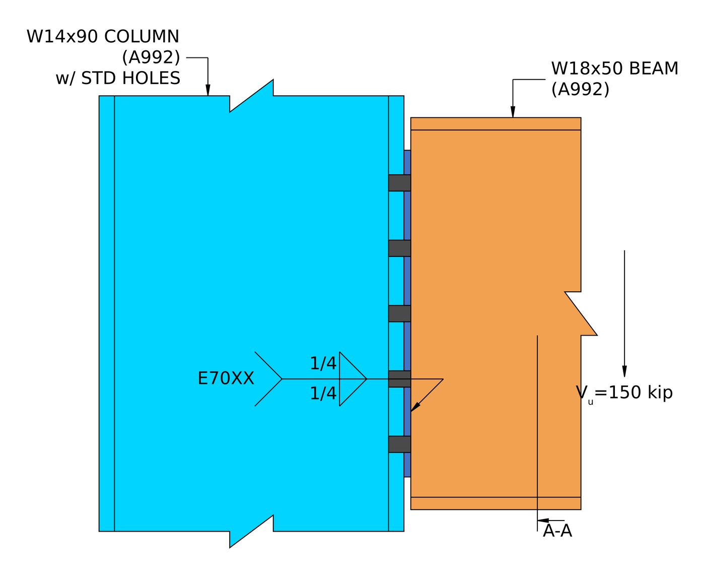
Élévation de l'exemple de connexion. The end plate is welded to the beam web in the shop and bolted to the column flange in the field.
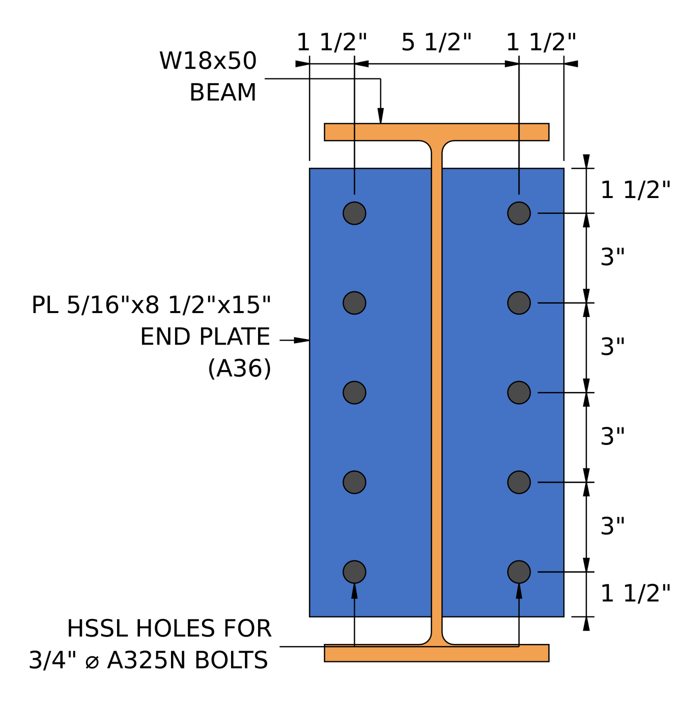
Section A-A. Two columns of five bolts at a 5 1/2 in gage, avec 1 1/2 in edge distances all round the plate.
How do you design a shear end plate connection? Les étapes en un coup d'œil
- Check the detailing limit at the beam side: the minimum plate depth.
- Check the fillet welds from the end plate to the beam web.
- Check the beam web in shear yielding.
- Check the detailing limits at the support side: espacement, edge distances and gage.
- Check the bolt group in shear.
- Check bolt bearing and tear-out on the end plate.
- Check bolt bearing and tear-out on the column flange.
- Combiner le cisaillement, roulement et déchirure par boulon pour une résistance efficace du groupe.
- Check block shear of the end plate.
- Check shear yielding and shear rupture of the end plate.
- Check end plate flexure using the double coped procedure.
- Check shear and moment interaction of the end plate.
Entrées de conception pour cet exemple
Le code de conception est AISC 360-16 LRFD. Les propriétés de la section proviennent du manuel AISC.
| Article | Symbole | Valeur |
|---|---|---|
| Cisaillement vertical pondéré | [mathin] V_{u} [mathin] | 150 kip |
| Beam | L18x50, A992 | |
| Profondeur du faisceau | [mathin] d_{bm} [mathin] | 18 in |
| Épaisseur de l'âme de la poutre | [mathin] t_{wb} [mathin] | 0.355 in |
| Largeur de l'aile de la poutre / thickness | [mathin] b_{fb},\ t_{fb} [mathin] | 7.5 in / 0.57 in |
| Beam T dimension / kdet | [mathin] T_{bm},\ k_{det,bm} [mathin] | 15.5 in / 1.25 in |
| Beam area | [mathin] A_{bm} [mathin] | 14.7 in² |
| Rendement du faisceau / contrainte de traction | [mathin] F_{yb},\ F_{ub} [mathin] | 50 KSI / 65 KSI |
| Colonne | L14x90, A992 | |
| Column depth / web thickness | [mathin] d_{sup},\ t_{ws} [mathin] | 14 in / 0.44 in |
| Column flange width / thickness | [mathin] b_{fs},\ t_{fs} [mathin] | 14.5 in / 0.71 in |
| Zone de colonne | [mathin] A_{sup} [mathin] | 26.5 in² |
| Rendement de la colonne / contrainte de traction | [mathin] F_{ys},\ F_{us} [mathin] | 50 KSI / 65 KSI |
| Module d'élasticité | [mathin] E [mathin] | 29000 KSI |
| Article | Symbole | Valeur |
|---|---|---|
| Plaque d'extrémité | PL 5/16 X 8 1/2 X 15, A36 | |
| End plate width / profondeur / thickness | [mathin] b_{p},\ d_{p},\ t_{p} [mathin] | 8.5 in / 15 in / 0.3125 in |
| End plate yield / contrainte de traction | [mathin] F_{yp},\ F_{up} [mathin] | 36 KSI / 58 KSI |
| Bolts at the column | 3/4 in A325-N, cisaillement simple | |
| Diamètre du boulon | [mathin] d_{b} [mathin] | 0.75 in |
| Traction nominale du boulon / contrainte de cisaillement | [mathin] F_{nt},\ F_{nv} [mathin] | 90 KSI / 54 KSI |
| Plans de cisaillement | [mathin] N_{s} [mathin] | 1 |
| Holes in end plate / colonne | Horizontal à fente courte (CSSS) / nommée (MST) | |
| Weld at the beam | 1/4 en filet, both sides of the web, E70XX | |
| Taille de soudure / force de remplissage | [mathin] W,\ F_{EXX} [mathin] | 0.25 in / 70 KSI |
| Géométrie | Symbole | Valeur |
|---|---|---|
| Rangées de boulons / espacement des rangs | [mathin] n_{r},\ s_{r} [mathin] | 5 / 3 in |
| Colonnes de boulons / gage | [mathin] n_{c},\ g_{s} [mathin] | 2 / 5.5 in |
| Total number of bolts | [mathin] N_{V} [mathin] | 10 |
| Vertical edge distance on end plate | [mathin] L_{ev} [mathin] | 1.5 in |
| Horizontal edge distance on end plate | [mathin] L_{eh} [mathin] | 1.5 in |
The plate dimensions add up from the drawing. The width is the two 1.5 in edge distances plus the 5.5 in gage, 8.5 in. The depth is the two 1.5 in edge distances plus four 3 in spaces, 15 in.
Étape 1: Detailing limit at the beam side
The end plate has to be deep enough to brace the beam end against rotation about its own axis and to give the welds enough length. The minimum is half the beam’s T dimension, so for a W18x50 with T = 15.5 in it is 7.75 in.
| Limite de détail | Limite (in) | Réel (in) | DCR | Résultat |
|---|---|---|---|---|
| Profondeur de connexion minimale | 7.750 | 15.000 | 0.517 | cdot K_a |
[math] DCR = \frac{d}{c} = \frac{(7.75)}{(15)} = 0.51667 [math]
DCR = 0.517 < 1.0, d'accord
Étape 2: Fillet weld from the end plate to the beam web (AISC 360-16 J2.4)
The whole reaction passes from the beam web into the end plate through the two fillet welds, one on each face of the web. Their strength depends on size and length, and the base metal on either side of the weld can limit how much of the weld size counts.
Limite de métal de base sur la taille de la soudure (Éq. manuel AISC. 9-2)
This is the largest weld size, en seizièmes de pouce, that the connected parts can support. Each weld line has the full end plate behind it, but the beam web carries a weld on both of its faces, so only half the web thickness is available to each weld. Avec [mathin] t_{p} = 0.3125\,in [mathin], [mathin] F_{up} = 58\,ksi [mathin], [mathin] t_{wb} = 0.355\,in [mathin] et [mathin] F_{ub} = 65\,ksi [mathin]:
[math] D_{max} = \frac{t_{p} F_{up} \le \frac{t_{wb}}{2} F_{ub}}{3.09\,kip/in \times F_{EXX}/F_{E70XX}} [math]
[math] D_{max} = \frac{(0.3125\,in) \times (58\,ksi) \le (0.1775\,in) \times (65\,ksi)}{(3.09\,kip/in) \times (1)} [math]
[math] D_{max} = 3.7338 [math]
The beam web side gives the smaller value, so only 3.7338/16 in, autour 0.233 in, de la 1/4 in weld can be counted.
Effective weld length
The weld can only run along the flat part of the web, so its length is the least of the plate depth, the beam’s T dimension, and the beam depth less the cope or kdet zone at the top and bottom. There is no cope, so the kdet of 1.25 in applies at each end. Each of the two weld lines is then reduced by 2W for the end returns. Avec [mathin] W = 0.25\,in [mathin], [mathin] d_{p} = 15\,in [mathin], [mathin] T_{bm} = 15.5\,in [mathin], [mathin] d_{bm} = 18\,in [mathin] et [mathin] k_{det,bm} = 1.25\,in [mathin]:
[math] L_{w} = 2 \left[ \min\left( d_{p},\, T_{bm},\, d_{bm} – \max\left(D_{ct}, k_{det,bm}\right) – \max\left(D_{cb}, k_{det,bm}\right) \right) – 2W \right] [math]
[math] L_{w} = 2 \times \left[ \min\left( (15\,in),\, (15.5\,in),\, (18\,in) – \max\left((0\,in), (1.25\,in)\right) – \max\left((0\,in), (1.25\,in)\right) \right) – 2 \times (0.25\,in) \right] [math]
[math] L_{w} = 29\,in [math]
Force de soudure
La charge est parallèle aux soudures, donc [mathin] \theta = 0 [mathin] et il n'y a pas d'augmentation directionnelle. Avec [mathin] F_{EXX} = 70\,ksi [mathin] et [mathin] \phi = 0.75 [mathin]:
[math] \phi R_{n} = \phi\, 0.6\, F_{EXX} \frac{\sqrt{2}}{2} \left( W \le \frac{D_{max}}{16} \right) \left[ 1 + 0.5 \left( \sin\theta \right)^{1.5} \right] L_{w} [math]
[math] \phi R_{n} = (0.75) \times 0.6 \times (70\,ksi) \times \frac{\sqrt{2}}{2} \times \left( (0.25\,in) \le \frac{(3.7338)}{(16)} \right) \times \left[ 1 + 0.5 \times (\sin(0))^{1.5} \right] \times (29\,in) [math]
[math] \phi R_{n} = 150.74\,kip [math]
DCR = 150 kip / 150.74 kip = 0.995 < 1.0, d'accord
This is the governing check. The weld is only just enough, and making it bigger would not help, because the 0.355 in beam web already limits the usable size to 0.233 in.
Étape 3: Beam web in shear yielding (AISC 360-16 J4.2)
The reaction travels along the beam web into the welds, so the web itself has to carry the full shear without yielding. The beam is not coped, so the full depth of the beam acts.
[math] A_{gv} = d_{bm}\, t_{wb} = (18\,in) \times (0.355\,in) = 6.39\,in^{2} [math]
Avec [mathin] F_{yb} = 50\,ksi [mathin] et [mathin] \phi = 1 [mathin]:
[math] \phi R_{n,sy} = \phi\, 0.6\, F_{yb} A_{gv} = (1) \times 0.6 \times (50\,ksi) \times (6.39\,in^{2}) = 191.7\,kip [math]
DCR = 150 kip / 191.7 kip = 0.782 < 1.0, d'accord
Étape 4: Detailing limits at the support side (AISC 360-16 J3.3, J3.4, J3.5)
The bolt layout has to be buildable and match the assumptions behind the strength equations. Les boulons trop serrés se déchirent entre les trous, les bords trop rapprochés se déchirent, and the gage has to leave room for the beam web, the welds and the bolt heads.
Pour un 3/4 in bolt the minimum spacing is [mathin] 2\tfrac{2}{3} d_{b} = 2\,in [mathin] (J3.3) and the minimum edge distance is 1 in (Tableau J3.4). The end plate has horizontal short slots, and its horizontal edge distance is measured from the end of the slot, so the Table J3.5 increment of 1/8 in raises its minimum to 1.125 in. On the column flange, the horizontal edge distance is what is left of the flange outside the bolts, [mathin] (b_{fs} – g_{s})/2 = (14.5 – 5.5)/2 = 4.5\,in [mathin].
| Limite de détail | Limite (in) | Réel (in) | DCR | Résultat |
|---|---|---|---|---|
| Espacement minimum des rangées de boulons | 2.000 | 3.000 | 0.667 | cdot K_a |
| Espacement maximal des rangées de boulons | 6.000 | 3.000 | 0.500 | cdot K_a |
| Distance minimale du bord vertical de la plaque | 1.000 | 1.500 | 0.667 | cdot K_a |
| Distance minimale du bord horizontal de la plaque | 1.125 | 1.500 | 0.750 | cdot K_a |
| Support minimum horizontal edge distance | 1.000 | 4.500 | 0.222 | cdot K_a |
| Minimum bolt gage at support | 4.375 | 5.500 | 0.795 | cdot K_a |
| Minimum bolt gage at end plate | 2.355 | 5.500 | 0.428 | cdot K_a |
Pour une limite minimale, le rapport est la limite sur la valeur réelle, et pour un maximum, c'est un dépassement réel de la limite. The governing row is the minimum bolt gage at the support:
[math] DCR = \frac{d}{c} = \frac{(4.375)}{(5.5)} = 0.79545 [math]
DCR = 0.795 < 1.0, d'accord
Étape 5: Bolt group shear at the support side (AISC 360-16 J3.6)
The bolts sit at the face of the column, in line with the reaction, and the two bolt columns are symmetric about the beam web. So the bolt group carries pure shear with no eccentricity, and every bolt takes an equal share.
Où [mathin] \phi = 0.75 [mathin], [mathin] F_{nv} = 54\,ksi [mathin], [mathin] d_{b} = 0.75\,in [mathin], [mathin] N_{s} = 1 [mathin], [mathin] N_{V} = 10 [mathin] et [mathin] h_{f} = 1 [mathin] parce qu'il n'y a pas de remplissage (J5.2(a)):
[math] \phi R_{n} = \phi\, F_{nv}\, \frac{\pi}{4} \left( d_{b} \right)^{2} N_{s}\, N_{V}\, h_{f} [math]
[math] \phi R_{n} = (0.75) \times (54\,ksi) \times \frac{\pi}{4} \times \left( (0.75\,in) \right)^{2} \times (1) \times (10) \times (1) [math]
[math] \phi R_{n} = 178.92\,kip [math]
DCR = 150 kip / 178.92 kip = 0.838 < 1.0, d'accord
Étape 6: Bolt bearing and tear-out on the end plate (AISC 360-16 J3.10)
Each bolt bears on the edge of its hole in the end plate. La plaque soit se déforme au niveau du trou (palier, plafonné à 2.4 d t Fu) or tears a strip out to the next hole or to the plate’s end (arrachement, 1.2 lc t Fu). The bolt nearest the end of the plate has the shortest clear distance, donc c'est le faible.
The slots run horizontally and the load is vertical, so the hole dimension across the member length is the standard [mathin] d_{h} = 0.8125\,in [mathin]. Distance libre pour le boulon de bord, avec [mathin] L_{ev} = 1.5\,in [mathin]:
[math] l_{c1} = L_{ev} – \frac{d_{h}}{2} = (1.5\,in) – \frac{(0.8125\,in)}{2} = 1.0938\,in [math]
Clear distance between bolts, avec [mathin] s_{r} = 3\,in [mathin]:
[math] l_{c2} = s_{r} – d_{h} = (3\,in) – (0.8125\,in) = 2.1875\,in [math]
Où [mathin] t_{p} = 0.3125\,in [mathin], [mathin] F_{up} = 58\,ksi [mathin], [mathin] N_{V} = 10 [mathin], [mathin] n_{r} = 5 [mathin] et [mathin] \phi = 0.75 [mathin]. The bracket is the strength of one line of five bolts, and the factor N_V / n_r = 2 counts both lines:
[math] \phi R_{n,tearout} = \phi \left[ \min\left(1.2\, l_{c1},\, 2.4\, d_{b}\right) t_{p} F_{up} + \min\left(1.2\, l_{c2},\, 2.4\, d_{b}\right) t_{p} F_{up} \left( n_{r} – 1 \right) \right] \left( \frac{N_{V}}{n_{r}} \right) [math]
[math] \phi R_{n,tearout} = (0.75) \times \left[ \min\left(1.2 \times (1.0938\,in),\, 2.4 \times (0.75\,in)\right) \times (0.3125\,in) \times (58\,ksi) + \min\left(1.2 \times (2.1875\,in),\, 2.4 \times (0.75\,in)\right) \times (0.3125\,in) \times (58\,ksi) \times \left( (5) – 1 \right) \right] \times \left( \frac{(10)}{(5)} \right) [math]
[math] \phi R_{n,tearout} = 231.43\,kip [math]
DCR = 150 kip / 231.43 kip = 0.648 < 1.0, d'accord
Tear-out governs the edge bolt, because 1.2 lc1 is less than 2.4 db. The inner bolts are capped by bearing.
Étape 7: Bolt bearing and tear-out on the column flange (AISC 360-16 J3.10)
The same check applies to the column flange. The bolts are in the middle of a tall column, with no edge above or below them, so every bolt bears like an inner bolt.
[math] l_{c2} = s_{r} – d_{h} = (3\,in) – (0.8125\,in) = 2.1875\,in [math]
Où [mathin] t_{fs} = 0.71\,in [mathin], [mathin] F_{us} = 65\,ksi [mathin] et [mathin] N_{V} = 10 [mathin]:
[math] \phi R_{n,tearout} = \phi\, \min\left(1.2\, l_{c2},\, 2.4\, d_{b}\right) t_{fs} F_{us}\, N_{V} [math]
[math] \phi R_{n,tearout} = (0.75) \times \min\left(1.2 \times (2.1875\,in),\, 2.4 \times (0.75\,in)\right) \times (0.71\,in) \times (65\,ksi) \times (10) [math]
[math] \phi R_{n,tearout} = 623.03\,kip [math]
DCR = 150 kip / 623.03 kip = 0.241 < 1.0, d'accord
Ce logiciel 0.71 in column flange is more than twice as thick as the end plate, so bearing on the column is rarely a concern with a thin shear end plate.
Étape 8: Résistance effective du groupe de boulons (AISC 360-16 J3.6 Commentaire)
Cisaille à boulon, le roulement et l'arrachement ne sont pas vraiment des contrôles séparés. Each bolt carries the least of its shear strength and its bearing or tear-out strength in every ply it passes through, et la force du groupe est la somme de ces valeurs par boulon.
Strength of one bolt in single shear:
[math] \phi r_{v} = \frac{\phi R_{n}}{N_{V}} = \frac{(178.92\,kip)}{(10)} = 17.892\,kip [math]
Bearing and tear-out of one bolt on the end plate, for the edge bolt and an inner bolt:
[math] \phi r_{n1e} = \phi\, \min\left(1.2\, l_{c1},\, 2.4\, d_{b}\right) t_{p} F_{up} = (0.75) \times \min\left(1.2 \times (1.0938\,in),\, 2.4 \times (0.75\,in)\right) \times (0.3125\,in) \times (58\,ksi) = 17.842\,kip [math]
[math] \phi r_{n1i} = \phi\, \min\left(1.2\, l_{c2},\, 2.4\, d_{b}\right) t_{p} F_{up} = (0.75) \times \min\left(1.2 \times (2.1875\,in),\, 2.4 \times (0.75\,in)\right) \times (0.3125\,in) \times (58\,ksi) = 24.469\,kip [math]
Bearing of one bolt on the column flange:
[math] \phi r_{n2} = \phi\, \min\left(1.2\, l_{c2},\, 2.4\, d_{b}\right) t_{fs} F_{us} = (0.75) \times \min\left(1.2 \times (2.1875\,in),\, 2.4 \times (0.75\,in)\right) \times (0.71\,in) \times (65\,ksi) = 62.303\,kip [math]
Bolts are numbered from the top of each line, and the report takes bolt 5 as the edge bolt. The top and bottom edge distances are both 1.5 in, so the edge bolt has the same 1.0938 in clear distance whichever end it is at:
[math] \phi r_{eff,1} = \min\left( \phi r_{v},\, \phi r_{n1i},\, \phi r_{n2} \right) = \min\left( (17.892\,kip),\, (24.469\,kip),\, (62.303\,kip) \right) = 17.892\,kip [math]
[math] \phi r_{eff,2} = \min\left( \phi r_{v},\, \phi r_{n1e},\, \phi r_{n2} \right) = \min\left( (17.892\,kip),\, (17.842\,kip),\, (62.303\,kip) \right) = 17.842\,kip [math]
| Verrouiller | Cisaille à boulon (kip) | Palier / arrachement, plaque d'extrémité (kip) | Palier / arrachement, bride de colonne (kip) | Force efficace (kip) |
|---|---|---|---|---|
| 1 | 17.89 | 24.47 | 62.30 | 17.89 |
| 2 | 17.89 | 24.47 | 62.30 | 17.89 |
| 3 | 17.89 | 24.47 | 62.30 | 17.89 |
| 4 | 17.89 | 24.47 | 62.30 | 17.89 |
| 5 | 17.89 | 17.84 | 62.30 | 17.84 |
Sum over one line, avec [mathin] n_{1} = 4 [mathin] bolts at the inner value and [mathin] n_{2} = 1 [mathin] at the edge value:
[math] \sum \phi r_{eff} = n_{1}\, \phi r_{eff,1} + n_{2}\, \phi r_{eff,2} = (4) \times (17.892\,kip) + (1) \times (17.842\,kip) = 89.411\,kip [math]
[math] \phi R_{n,eff} = \left( \frac{N_{V}}{n_{r}} \right) \sum \phi r_{eff} = \left( \frac{(10)}{(5)} \right) \times (89.411\,kip) = 178.82\,kip [math]
DCR = 150 kip / 178.82 kip = 0.839 < 1.0, d'accord
Bolt shear governs four bolts in each line, and tear-out on the 5/16 in plate governs the edge bolt by 0.05 kip. That is why the effective strength comes out a fraction below the bolt shear strength in Step 5. Vous pouvez exécuter la même connexion dans le calculateur de conception de connexion gratuit and try a larger edge distance to see the two values meet.
Étape 9: Block shear of the end plate (AISC 360-16 J4.3)
A block of the end plate can tear out on each side of the beam web: shear along the bolt line to the end of the plate, plus tension across to the plate’s outer edge. That makes two L-shaped blocks, one per bolt column, so the areas below use [mathin] 2t_{p} = 0.625\,in [mathin] and count one bolt column on each side.
Net area in tension. The tension plane runs horizontally, along the slots, so it uses the slot length [mathin] d_{h} = 1\,in [mathin], avec [mathin] n_{c} = 2 [mathin], [mathin] s_{c} = 0\,in [mathin] et [mathin] L_{eh} = 1.5\,in [mathin]. Chaque trou ajoute 1/16 en cas de dommages lors du poinçonnage (B4.3):
[math] A_{nt} = 2t_{p} \left[ \left( \frac{n_{c}}{2} – 1 \right) s_{c} + L_{eh} – \left( \frac{n_{c}}{2} – 0.5 \right) \left( d_{h} + 0.0625\,in \right) \right] [math]
[math] A_{nt} = (0.625\,in) \times \left[ ((1)-1) \times (0\,in) + (1.5\,in) – ((1) – 0.5) \times ((1\,in) + (0.0625\,in)) \right] = 0.60547\,in^{2} [math]
Gross and net areas in shear. The shear plane runs vertically, across the slots, so the net area uses [mathin] d_{h} = 0.8125\,in [mathin]:
[math] A_{gv} = 2t_{p} \left[ L_{ev} + (n_{r}-1)\, s_{r} \right] = (0.625\,in) \times \left[ (1.5\,in) + ((5)-1) \times (3\,in) \right] = 8.4375\,in^{2} [math]
[math] A_{nv} = 2t_{p} \left[ d_{p} – L_{ev} – (n_{r} – 0.5)\left( d_{h} + 0.0625\,in \right) \right] [math]
[math] A_{nv} = (0.625\,in) \times \left[ (15\,in) – (1.5\,in) – ((5) – 0.5) \times ((0.8125\,in) + (0.0625\,in)) \right] = 5.9766\,in^{2} [math]
Résistance au cisaillement des blocs, avec [mathin] U_{bs} = 1 [mathin] because each block has a single bolt column and the tension is uniform, [mathin] F_{up} = 58\,ksi [mathin], [mathin] F_{yp} = 36\,ksi [mathin] et [mathin] \phi = 0.75 [mathin]:
[math] \phi R_{n} = \phi \left( 0.6\, F_{up} A_{nv} + U_{bs} F_{up} A_{nt} \le 0.6\, F_{yp} A_{gv} + U_{bs} F_{up} A_{nt} \right) [math]
[math] \phi R_{n} = (0.75) \times \left( 0.6 \times (58\,ksi) \times (5.9766\,in^{2}) + (1) \times (58\,ksi) \times (0.60547\,in^{2}) \le 0.6 \times (36\,ksi) \times (8.4375\,in^{2}) + (1) \times (58\,ksi) \times (0.60547\,in^{2}) \right) [math]
[math] \phi R_{n} = 163.03\,kip [math]
DCR = 150 kip / 163.03 kip = 0.920 < 1.0, d'accord
The shear yielding side of the equation governs. A36 has a low yield-to-tensile ratio, so the gross shear plane yields before the net shear plane ruptures. This is the second highest ratio in the connection.
Étape 10: Shear yielding and shear rupture of the end plate (AISC 360-16 J4.2)
The full reaction passes down through the end plate as vertical shear on two planes, un de chaque côté de l'âme de la poutre. La section brute ne doit pas céder, et la section du filet à travers les trous de boulons ne doit pas se rompre.
Cédant au cisaillement (Eq. J4-3)
Avec [mathin] n_{sp} = 2 [mathin] plans de cisaillement:
[math] A_{gv} = d_{p}\, n_{sp}\, t_{p} = (15\,in) \times (0.625\,in) = 9.375\,in^{2} [math]
[math] \phi R_{n,sy} = \phi\, 0.6\, F_{yp} A_{gv} = (1) \times 0.6 \times (36\,ksi) \times (9.375\,in^{2}) = 202.5\,kip [math]
Rupture par cisaillement (Eq. J4-4)
[math] A_{nv} = n_{sp}\, t_{p} \left[ d_{p} – n_{r}\left( d_{h} + 0.0625\,in \right) \right] = (0.625\,in) \times \left[ (15\,in) – (5) \times ((0.8125\,in) + (0.0625\,in)) \right] = 6.6406\,in^{2} [math]
[math] \phi R_{n,sr} = \phi\, 0.6\, F_{up} A_{nv} = (0.75) \times 0.6 \times (58\,ksi) \times (6.6406\,in^{2}) = 173.32\,kip [math]
[math] \phi R_{n} = \min\left( \phi R_{n,sy},\, \phi R_{n,sr} \right) = \min\left( (202.5\,kip),\, (173.32\,kip) \right) = 173.32\,kip [math]
DCR = 150 kip / 173.32 kip = 0.865 < 1.0, d'accord
Étape 11: End plate flexure using the double coped procedure (AISC 360-16 F11.2)
The bolts are 2 3/4 in out from the web on each side, so each half of the end plate bends as a short cantilever from the web to its bolt line. A thin plate can buckle sideways before it yields. The AISC Manual handles this with the procedure for a beam coped at both flanges, treating each half of the plate like a beam web with the flanges cut away. The unbraced length is the distance from the face of the web to the bolt line, [mathin] L_{b} = (g_{s} – t_{wb})/2 = (5.5 – 0.355)/2 = 2.5725\,in [mathin].
Range check
Où [mathin] E = 29000\,ksi [mathin], [mathin] F_{yp} = 36\,ksi [mathin], [mathin] d_{p} = 15\,in [mathin] et [mathin] t_{p} = 0.3125\,in [mathin]:
[math] \frac{L_{b} d}{t^{2}} = \frac{(2.5725\,in) \times (15\,in)}{(0.3125\,in)^{2}} = 395.14 [math]
[math] \frac{0.08 E}{F_{y}} = \frac{0.08 \times (29000\,ksi)}{(36\,ksi)} = 64.444 \qquad \frac{1.9 E}{F_{y}} = \frac{1.9 \times (29000\,ksi)}{(36\,ksi)} = 1530.6 [math]
Donc [mathin] \frac{0.08E}{F_{y}} \lt \frac{L_{b} d}{t^{2}} \le \frac{1.9E}{F_{y}} [mathin], et éq. F11-2 s'applique.
Section moduli of the end plate
[math] Z = \frac{t_{p} \left( d_{p} \right)^{2}}{4} = \frac{(0.3125\,in) \times ((15\,in))^{2}}{4} = 17.578\,in^{3} [math]
[math] S = \frac{t_{p} \left( d_{p} \right)^{2}}{6} = \frac{(0.3125\,in) \times ((15\,in))^{2}}{6} = 11.719\,in^{3} [math]
Facteur de modification du déversement (Éq. manuel AISC. 9-15)
The cope depth is taken as zero, [mathin] d_{ct} = 0\,in [mathin]:
[math] C_{b} = \left[ 3 + \ln\left( \frac{L_{b}}{d_{p}} \right) \right] \left( 1 – \frac{d_{ct}}{d_{p}} \right) \ge 1.84 [math]
[math] C_{b} = \left[ 3 + \ln\left( \frac{(2.5725\,in)}{(15\,in)} \right) \right] \times \left( 1 – \frac{(0\,in)}{(15\,in)} \right) \ge 1.84 [math]
[math] C_{b} = 1.84 [math]
Flexural strength
Avec [mathin] \phi = 0.9 [mathin], and a factor of 2 for the two halves of the plate:
[math] \phi M_{n} = \phi \left[ C_{b} \left[ 1.52 – 0.274 \left( \frac{L_{b} d}{t^{2}} \right) \left( \frac{F_{yp}}{E} \right) \right] F_{yp} S \le F_{yp} Z \right] 2 [math]
[math] \phi M_{n} = (0.9) \times \left[ (1.84) \times \left[ 1.52 – 0.274 \times ((395.14)) \times \left( \frac{(36\,ksi)}{(29000\,ksi)} \right) \right] \times (36\,ksi) \times (11.719\,in^{3}) \le (36\,ksi) \times (17.578\,in^{3}) \right] \times 2 [math]
[math] \phi M_{n} = 94.922\,kip\text{-}ft \;(1139.1\,kip\text{-}in) [math]
The plastic moment cap [mathin] F_{yp} Z [mathin] governs, so buckling does not reduce the strength over this short length.
Equivalent shear capacity
[math] \phi V_{n} = \frac{\phi M_{n}}{L_{b}} = \frac{(94.922\,kip\text{-}ft)}{(2.5725\,in)} = 442.78\,kip [math]
DCR = 150 kip / 442.78 kip = 0.339 < 1.0, d'accord
Étape 12: Shear and moment interaction of the end plate (Éq. manuel AISC. 10-5)
The end plate carries shear and bending at the same section at the same time, donc les deux doivent être vérifiés ensemble. The Manual uses a circular interaction between the shear yielding strength and the flexural strength.
The moment in the plate is the reaction times the unbraced length, avec [mathin] V_{r} = 150\,kip [mathin] et [mathin] L_{b} = 2.5725\,in [mathin]:
[math] M_{r} = V_{r}\, L_{b} = (150\,kip) \times (2.5725\,in) = 32.156\,kip\text{-}ft [math]
Avec [mathin] \phi V_{n} = 202.5\,kip [mathin] from shear yielding in Step 10 et [mathin] \phi M_{n} = 94.922\,kip\text{-}ft [mathin] de l'étape 11:
[math] I_{nt} = \left( \frac{V_{r}}{\phi V_{n}} \right)^{2} + \left( \frac{M_{r}}{\phi M_{n}} \right)^{2} [math]
[math] I_{nt} = \left( \frac{(150\,kip)}{(202.5\,kip)} \right)^{2} + \left( \frac{(32.156\,kip\text{-}ft)}{(94.922\,kip\text{-}ft)} \right)^{2} = 0.66346 [math]
DCR = 0.66346 / 1.0 = 0.663 < 1.0, d'accord
The short lever arm keeps the moment small, so most of the interaction comes from shear.
Summary of the shear end plate connection design checks
| Vérification de la conception | Demande | Capacité | DCR | Résultat |
|---|---|---|---|---|
| Limites de détail côté poutre | 7.750 in | 15.000 in | 0.517 | cdot K_a |
| Weld at beam side | 150.000 kip | 150.739 kip | 0.995 | cdot K_a |
| Beam web in shear | 150.000 kip | 191.700 kip | 0.782 | cdot K_a |
| Limites détaillées côté support | 4.375 in | 5.500 in | 0.795 | cdot K_a |
| Cisaillement de groupe de boulons | 150.000 kip | 178.924 kip | 0.838 | cdot K_a |
| Roulement de boulon et arrachement, plaque d'extrémité | 150.000 kip | 231.434 kip | 0.648 | cdot K_a |
| Roulement de boulon et arrachement, bride de colonne | 150.000 kip | 623.025 kip | 0.241 | cdot K_a |
| Résistance effective du groupe de boulons | 150.000 kip | 178.822 kip | 0.839 | cdot K_a |
| Block shear of end plate | 150.000 kip | 163.025 kip | 0.920 | cdot K_a |
| Shear yielding and rupture of end plate | 150.000 kip | 173.320 kip | 0.865 | cdot K_a |
| End plate flexure (procédure à double face) | 150.000 kip | 442.784 kip | 0.339 | cdot K_a |
| Shear and moment interaction of end plate | 0.663 | 1.000 | 0.663 | cdot K_a |
La connexion passe tous les contrôles. The weld at the beam side governs at 0.995, because the 0.355 in beam web limits the usable weld size to about 0.233 in. Block shear of the end plate is next at 0.920, then shear rupture of the end plate at 0.865. Plate flexure is far from critical at 0.339, which is typical for a shear end plate: the bolts sit close to the web, so the lever arm is short.
Que changer si une vérification échoue
- Weld at the beam side: a longer weld helps, so use a deeper end plate, up to the beam’s T dimension. A bigger fillet adds nothing once the beam web base metal limit governs. A beam with a thicker web raises that limit.
- Beam web shear: pick a beam with a thicker or deeper web. The end plate cannot help this check.
- Bolt shear or effective strength: add a bolt row or use a larger bolt. A325-X (threads excluded) or A490 bolts raise the shear stress.
- Tear-out on the end plate: increase the vertical edge distance, or use a thicker plate.
- Cisaillement de bloc, shear yielding or shear rupture of the end plate: use a thicker or deeper plate. A longer horizontal edge distance also adds to the block shear tension area.
- Plate flexure or interaction: reduce the gage so L_b is shorter, or use a thicker plate. Keep the plate thin enough to stay flexible, because a stiff end plate starts to act like a moment connection.
- Gage or edge distance at the support: adjust the gage within the column flange width. The gage has to clear the beam web and its welds on the plate side and suit the column flange on the support side.
Questions fréquentes
What is the difference between a shear end plate and a moment end plate?
A shear end plate is welded to the beam web only, is thin (5/16 in here), and is designed to flex so the beam end can rotate. A moment end plate, flush or extended, is also welded to the beam flanges, is much thicker, and uses its bolts in tension to resist the beam’s end moment. This example only carries vertical shear, so it is a simple connection.
Why is there no bolt group eccentricity in this example?
The bolts sit at the face of the column, on the line where the reaction is delivered, and the two bolt columns are placed symmetrically on either side of the beam web. So the bolt group carries pure shear and every bolt takes the same share. The bolt group strength is simply the strength of one bolt times the ten bolts.
Why does the beam web, not the end plate, limit the weld?
Éq. manuel AISC. 9-2 limits the weld size to what the base metal next to it can carry. The beam web has a fillet weld on both of its faces, so each weld is backed by only half the 0.355 in web. Each weld line has the full 5/16 in end plate behind it. The web gives the smaller value, 3.7338 sixteenths, or about 0.233 in, which is less than the 1/4 in weld that was specified.
Why does the end plate have short-slotted holes?
Horizontal short slots in the end plate give the erector some fit-up tolerance across the beam, which helps when the column or the beam length is slightly off. Because the slots are horizontal and the load is vertical, bearing and tear-out use the standard hole dimension across the slot. The slot length only appears in the block shear tension area and in the 1/8 in edge distance increment from Table J3.5.
How thick should a shear end plate be?
Thin enough to rotate. Partie du manuel AISC 10 limits end plates in this kind of simple connection to 1/4 dans 3/8 en épaisseur, with a gage of 3 1/2 dans 5 1/2 in, so the plate can bend as the beam end rotates. A thicker plate or a narrower gage makes the connection stiffer and starts to pull moment into the column. This example uses a 5/16 in plate at a 5 1/2 in gage.
Which check usually governs a shear end plate connection?
On a beam with a thin web, the weld to the beam web often governs, because the web base metal limits the weld size and the weld length is capped by the beam’s T dimension. On a thicker web the end plate itself, through block shear or shear rupture, usually takes over. In this example the weld governs at 0.995, with block shear of the end plate next at 0.920.
Cet exemple suit-il la 15e édition de l'AISC ou le manuel de la 16e édition de l'AISC?
Il suit l'AISC 360-16 et le manuel AISC 15e édition, qui est écrit autour de cette spécification. Le manuel AISC 16e édition s'associe au dernier 360-22 spécification. The limit states for a shear end plate connection are the same in both, mais les références aux clauses et aux pages se déplacent, alors vérifiez-les par rapport à l'édition utilisée par votre projet.
Comment cela changerait-il pour AISC ASD au lieu de LRFD?
Les états limites et les résistances nominales sont identiques. Avec AISC ASD, vous comparez la réaction au niveau de service à la résistance nominale divisée par un facteur de sécurité au lieu de la multiplier par un facteur de résistance.. Un facteur de résistance de 0.75 devient un facteur de sécurité de 2.00, shear yielding’s 1.00 devient 1.50, and flexure’s 0.90 devient 1.67. Les combinaisons de charges changent également, donc la demande est plus faible.
Design a shear end plate connection for free
Chaque numéro sur cette page provient d'une seule solution. Pick the end plate configuration, entrez votre faisceau, colonne, assiette, boulons, weld and reaction, et voyez chacune de ces vérifications dans votre navigateur. Il n'y a rien à installer.
Le module SkyCiv Connection Design est le logiciel de conception de connexion derrière cet exemple. Il vous donne le rapport de calcul complet avec chaque équation et vos chiffres, comme les étapes ci-dessus, plus toutes les capacités et DCR, selon AISC 360-16 (LRFD et TSA) et AS 4100:2020. Ce logiciel calculateur de boulons et calculateur de soudure couvrir le groupe de boulons et les contrôles de soudure seuls.
Références
- AISC 360-16, Spécification pour les bâtiments en acier de construction: B3.4, B4.3, F11.2 (Eq. F11-2), J2.4 (Eq. J2-4), J3.3, J3.4 (Tableau J3.4), J3.5 (Tableau J3.5), J3.6 (Eq. J3-1) et commentaire, J3.10 (Eq. J3-6a, J3-6c), J4.2 (Eq. J4-3, J4-4), J4.3 (Eq. J4-5), J5.2(a).
- Manuel de construction en acier AISC, 15e édition: Partie 9, Eq. 9-2 et éq. 9-15 (de SkiCiv 9-9); Partie 10, weld length less 2w at the ends, et éq. 10-5 (de SkiCiv 10-90).
- Conception d'assemblages en acier utilisant AISC 360-16
- Boulons et soudures dans la conception de connexion SkyCiv

Harold Munalem
Chef de produit, Conception de connexion
10+ années dans la conception d'assemblages en acier
LinkedIn
