
Extended single plate connection design to AISC 360 is the shear tab procedure for a plate that reaches well past the support, usually so the beam can frame into a column web and clear the column flanges. You check the bolt group for the full eccentricity, the plate thickness for ductility, bolt bearing and tear-out on the plate and the beam web, cisaillement de bloc, shear yielding and rupture, plate flexure and buckling, shear and flexure interaction, and the weld to the support. The long plate makes the bolt group eccentricity and the plate bending much larger than in a conventional shear tab, and that is what drives the design.
This page works one real example from start to finish: a W24x55 beam framing into the web of a W14x90 column, avec un 100 kip réaction LRFD, through a 3/8 en x 13 en x 21 in A36 plate with fourteen 3/4 in A325-N bolts in two columns of seven. The design is to AISC 360-16 et le manuel AISC 15e édition. Chaque équation est écrite avec ses chiffres, in the same order as the AISC calc sheet that the Conception de connexion SkyCiv module produces for this connection.
What is an extended single plate connection?
An extended single plate connection is a shear tab that is longer than the conventional configuration allows. The plate is shop welded to the support and field bolted to the beam web, as with any single plate, but the bolts sit far enough from the weld that the AISC Manual’s simplified Table 10-9 approach no longer applies. It is still a simple connection under AISC 360-16 B3.4, il est donc détaillé de tourner plutôt que de résister au moment.
The most common use is a beam framing into a column web. The beam end has to sit outside the column flanges, so the plate reaches out from the web to meet it. In this example the beam end is 7 3/4 in from the column web. A plate that long bends a lot more than a short tab, so the bolt group is designed for the full eccentricity and the plate is checked for buckling as well as yielding. It is one type of connexion de cisaillement, alongside the connexion à double angle, l' connexion à angle unique et la cisaille connexion par plaque d'extrémité. You can check this example directly in the calculateur de connexion à plaque unique, which covers both the conventional and extended configurations.
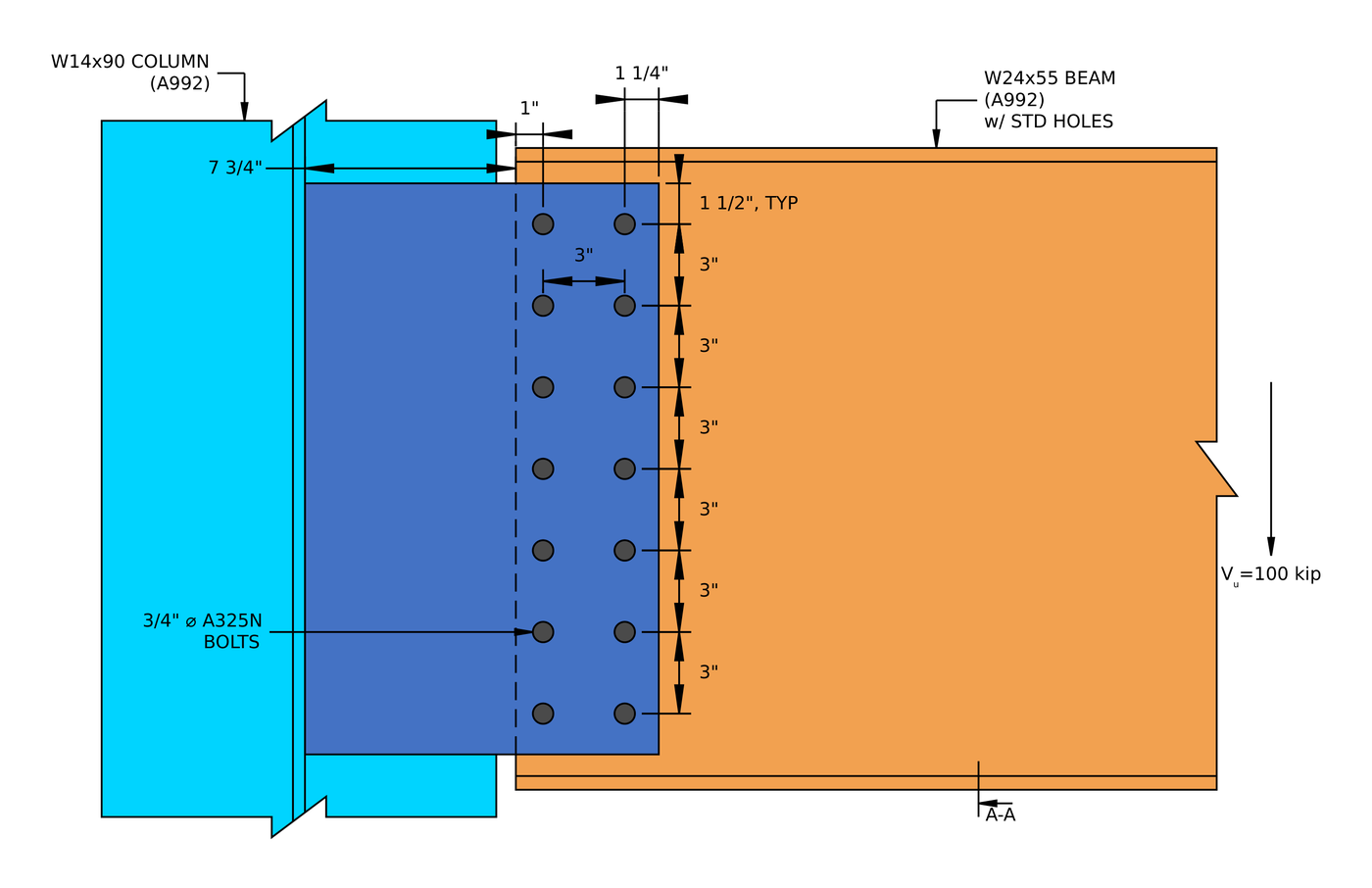
Élévation de l'exemple de connexion. The beam end sits 7 3/4 in from the column web, outside the column flanges, and the first bolt column is 1 in in from the beam end.
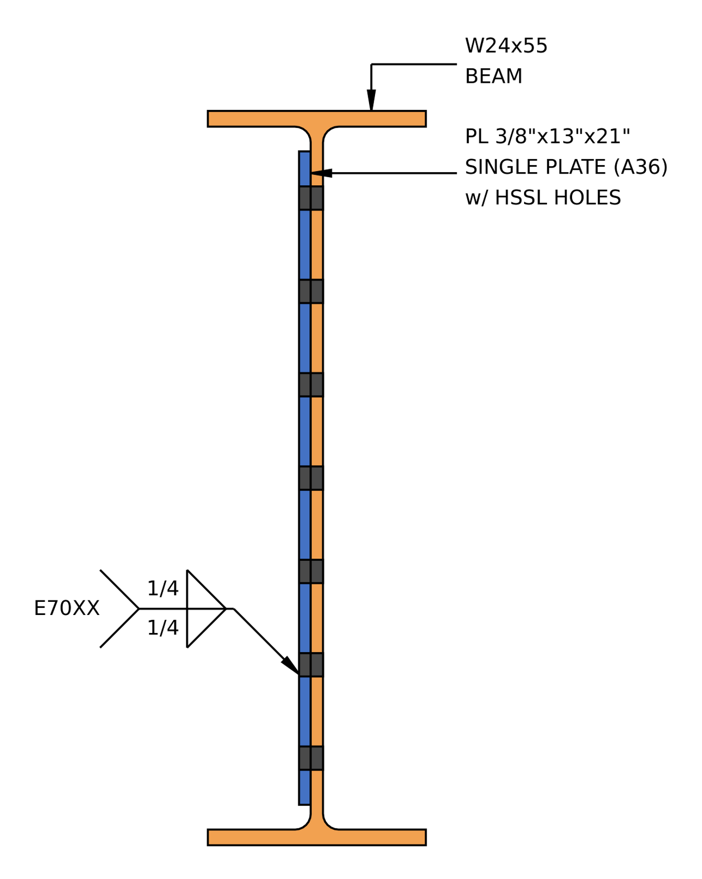
Section A-A. La plaque comporte des trous horizontaux à fentes courtes et un 1/4 in fillet weld on both sides to the column web.
How do you design an extended single plate connection? Les étapes en un coup d'œil
- Vérifiez les limites de détail au niveau de la poutre: espacement des boulons, distances aux bords, profondeur de la plaque.
- Find the bolt group shear strength by the instantaneous center of rotation, for the full eccentricity.
- Vérifier la ductilité de la plaque: the plate must not be stronger in bending than the bolt group.
- Vérifier le roulement du boulon et l'arrachement de la plaque.
- Vérifier le roulement des boulons et l'arrachement de l'âme de la poutre.
- Combiner le cisaillement, roulement et déchirure par boulon pour une résistance efficace du groupe.
- Vérifier le cisaillement du bloc de la plaque.
- Vérifier la résistance au cisaillement et la rupture par cisaillement de la plaque.
- Check plate flexure and buckling using the double coped beam procedure.
- Check shear and flexure interaction for yielding.
- Check shear and flexure interaction for rupture.
- Vérifiez la limite de détail au support.
- Check the weld size needed to develop the plate.
- Check the weld strength to the column web.
Entrées de conception pour cet exemple
Le code de conception est AISC 360-16 LRFD. Les propriétés de la section proviennent du manuel AISC.
| Article | Symbole | Valeur |
|---|---|---|
| Cisaillement vertical pondéré | [mathin] V_{u} [mathin] | 100 kip |
| Beam | W24x55, A992 | |
| Profondeur du faisceau | [mathin] d_{bm} [mathin] | 23.6 in |
| Épaisseur de l'âme de la poutre | [mathin] t_{wb} [mathin] | 0.395 in |
| Largeur de l'aile de la poutre / thickness | [mathin] b_{fb},\ t_{fb} [mathin] | 7.01 in / 0.505 in |
| Beam area | [mathin] A_{bm} [mathin] | 16.2 in² |
| Rendement du faisceau / contrainte de traction | [mathin] F_{yb},\ F_{ub} [mathin] | 50 KSI / 65 KSI |
| Colonne | L14x90, A992 | |
| Column depth / web thickness | [mathin] d_{sup},\ t_{ws} [mathin] | 14 in / 0.44 in |
| Column flange width / thickness | [mathin] b_{fs},\ t_{fs} [mathin] | 14.5 in / 0.71 in |
| Zone de colonne | [mathin] A_{sup} [mathin] | 26.5 in² |
| Rendement de la colonne / contrainte de traction | [mathin] F_{ys},\ F_{us} [mathin] | 50 KSI / 65 KSI |
| Module d'élasticité | [mathin] E [mathin] | 29000 KSI |
| Article | Symbole | Valeur |
|---|---|---|
| assiette (plaque unique) | PL 3/8 X 13 X 21, A36 | |
| Largeur de plaque / profondeur / thickness | [mathin] b_{p},\ d_{p},\ t_{p} [mathin] | 13 in / 21 in / 0.375 in |
| Rendement des plaques / contrainte de traction | [mathin] F_{yp},\ F_{up} [mathin] | 36 KSI / 58 KSI |
| Boulons | 3/4 in A325-N, cisaillement simple | |
| Diamètre du boulon | [mathin] d_{b} [mathin] | 0.75 in |
| Traction nominale du boulon / contrainte de cisaillement | [mathin] F_{nt},\ F_{nv} [mathin] | 90 KSI / 54 KSI |
| Plans de cisaillement | [mathin] N_{s} [mathin] | 1 |
| Trous dans la plaque / poutre | Horizontal à fente courte (CSSS) / nommée (MST) | |
| Souder | 1/4 en filet, les deux côtés, E70XX | |
| Taille de soudure / force de remplissage | [mathin] W,\ F_{EXX} [mathin] | 0.25 in / 70 KSI |
| Géométrie | Symbole | Valeur |
|---|---|---|
| Rangées de boulons / espacement des rangs | [mathin] n_{r},\ s_{r} [mathin] | 7 / 3 in |
| Colonnes de boulons / espacement des colonnes | [mathin] n_{c},\ s_{c} [mathin] | 2 / 3 in |
| Beam web clearance (column web to beam end) | [mathin] clr [mathin] | 7.75 in |
| Distance du bord horizontal sur l'âme de la poutre | [mathin] L_{eh,bm} [mathin] | 1 in |
| Distance du bord horizontal sur la plaque | [mathin] L_{eh,pl} [mathin] | 1.25 in |
| Distance du bord vertical sur la plaque | [mathin] L_{ev,pl} [mathin] | 1.5 in |
| Bolt group eccentricity | [mathin] e [mathin] | 10.25 in |
The plate width adds up from the drawing: 7.75 in to the beam end, 1 in to the first bolt column, 3 in between columns and 1.25 in to the plate edge, 13 in in total. The plate depth is the two 1.5 in edge distances plus six 3 in spaces, 21 in.
Étape 1: Limites de détail côté poutre (AISC 360-16 J3.3, J3.4, J3.5)
Avant tout contrôle de solidité, la disposition des boulons doit être constructible et correspondre aux hypothèses derrière les équations de résistance. Les boulons trop serrés se déchirent entre les trous, les bords trop rapprochés se déchirent, et une plaque trop courte ou trop profonde modifie la façon dont la connexion tourne.
Pour un 3/4 in bolt the minimum spacing is [mathin] 2\tfrac{2}{3} d_{b} = 2\,in [mathin] (J3.3) and the minimum edge distance is 1 in (Tableau J3.4). The plate has horizontal short slots, and its horizontal edge distance is measured from the end of the slot, so the Table J3.5 increment of 1/8 in raises its minimum to 1.125 in. La profondeur de la plaque doit être au moins égale à la moitié de la dimension T de la poutre, 20 3/4 in for a W24x55, la connexion est donc suffisamment rigide pour soutenir l'extrémité de la poutre, and it must also fit within the beam web.
| Limite de détail | Limite (in) | Réel (in) | DCR | Résultat |
|---|---|---|---|---|
| Espacement minimum des rangées de boulons | 2.000 | 3.000 | 0.667 | cdot K_a |
| Espacement maximal des rangées de boulons | 6.000 | 3.000 | 0.500 | cdot K_a |
| Minimum bolt column spacing | 2.000 | 3.000 | 0.667 | cdot K_a |
| Maximum bolt column spacing | 6.000 | 3.000 | 0.500 | cdot K_a |
| Distance minimale du bord vertical de la plaque | 1.000 | 1.500 | 0.667 | cdot K_a |
| Distance minimale du bord horizontal de la plaque | 1.125 | 1.250 | 0.900 | cdot K_a |
| Distance minimale du bord horizontal de la poutre | 1.000 | 1.000 | 1.000 | cdot K_a |
| Profondeur de connexion minimale | 10.375 | 21.000 | 0.494 | cdot K_a |
| Profondeur de connexion maximale | 21.375 | 21.000 | 0.982 | cdot K_a |
Pour une limite minimale, le rapport est la limite sur la valeur réelle, et pour un maximum, c'est un dépassement réel de la limite. The governing row is the horizontal edge distance on the beam web, which sits exactly at the 1 in minimum:
[math] DCR = \frac{d}{c} = \frac{(1)}{(1)} = 1 [math]
DCR = 1.000 ≤ 1.0, d'accord
The plate depth is also close to its upper limit at 0.982. A 21 in plate with seven rows is about as deep as this beam can take.
Étape 2: Résistance au cisaillement du groupe de boulons par le centre de rotation instantané (AISC 360-16 J3.6)
The beam reaction reaches the plate at the bolt group, a long way from the weld, so the bolts carry a large moment as well as the shear. Le centre de rotation instantané (ICOR) La méthode trouve le point autour duquel le groupe de boulons tourne et le transforme en un coefficient C, quel est le nombre de boulons’ valeur de la résistance au cisaillement que le groupe offre réellement.
Excentricité de conception
For a conventional single plate, Tableau manuel AISC 10-9 lets you design the bolts for a reduced eccentricity. That table does not cover the extended configuration, so the bolt group is designed for the full distance from the weld line to the centroid of the bolt group. Here that is the beam clearance, plus the edge distance to the first bolt column, plus half the column spacing:
[math] e = clr + L_{eh,bm} + \frac{s_{c}}{2} = 7.75\,in + 1\,in + \frac{3\,in}{2} = 10.25\,in [math]
Résistance d'un boulon
Avec [mathin] \phi = 0.75 [mathin], [mathin] F_{nv} = 54\,ksi [mathin], [mathin] d_{b} = 0.75\,in [mathin] et [mathin] N_{s} = 1 [mathin]:
[math] \phi r_{v} = \phi\, F_{nv}\, \frac{\pi}{4} \left( d_{b} \right)^{2} N_{s}\, h_{f} = 17.892\,kip [math]
Ici [mathin] h_{f} = 1 [mathin] parce qu'il n'y a pas de remplissage (AISC 360-16 J5.2(a)):
[math] h_{f} = 0.85 \lt 1 – (0.4) \times \left( (0\,in) – (0.25\,in) \right) \le 1 \;\Rightarrow\; h_{f} = 1 [math]
Localisation du centre instantané
Verrouiller 1 is at the bottom-left corner of the group, avec les coordonnées ci-dessous. Le CI est trouvé par itération, en utilisant la courbe charge-déformation de l'équation manuelle AISC (7-1) sur les pages 7-6 à 7-8. Ce logiciel calcul du groupe de boulons à l'aide d'ICOR parcourt cette itération dans son intégralité.
| Verrouiller | X (in) | Y (in) |
|---|---|---|
| 1 | 0.00 | 0.00 |
| 2 | 0.00 | 3.00 |
| 3 | 0.00 | 6.00 |
| 4 | 0.00 | 9.00 |
| 5 | 0.00 | 12.00 |
| 6 | 0.00 | 15.00 |
| 7 | 0.00 | 18.00 |
| 8 | 3.00 | 0.00 |
| 9 | 3.00 | 3.00 |
| 10 | 3.00 | 6.00 |
| 11 | 3.00 | 9.00 |
| 12 | 3.00 | 12.00 |
| 13 | 3.00 | 15.00 |
| 14 | 3.00 | 18.00 |
L'itération converge avec le IC à:
[math] x_{ic} = -1.3636\,in, \qquad y_{ic} = 9\,in [math]
The IC sits level with the middle row and just outside the left bolt column. Les réactions du boulon à cet endroit sont:
| Verrouiller | R (kip) | Rx (kip) | Ry (kip) | Mn (poulet dans) |
|---|---|---|---|---|
| 1 | 17.44 | 17.24 | 2.61 | 158.76 |
| 2 | 16.64 | 16.23 | 3.69 | 102.40 |
| 3 | 14.40 | 13.11 | 5.96 | 47.45 |
| 4 | 10.37 | 0.00 | 10.37 | 14.15 |
| 5 | 14.40 | -13.11 | 5.96 | 47.45 |
| 6 | 16.64 | -16.23 | 3.69 | 102.40 |
| 7 | 17.44 | -17.24 | 2.61 | 158.76 |
| 8 | 17.56 | 15.80 | 7.66 | 175.65 |
| 9 | 17.09 | 13.82 | 10.05 | 126.77 |
| 10 | 16.20 | 9.18 | 13.35 | 85.78 |
| 11 | 15.53 | 0.00 | 15.53 | 67.77 |
| 12 | 16.20 | -9.18 | 13.35 | 85.78 |
| 13 | 17.09 | -13.82 | 10.05 | 126.77 |
| 14 | 17.56 | -15.80 | 7.66 | 175.65 |
Cela donne les deux coefficients utilisés dans le reste du plan:
[math] C = 6.29 \qquad C’ = 72.195\,in [math]
Fourteen bolts deliver only 6.29 boulons’ worth of vertical shear at a 10.25 in eccentricity, so more than half the group’s concentric strength goes into resisting the moment. C’ est le coefficient du moment seul, dont la ductilité est vérifiée à l'étape 3 les usages.
Force du groupe de boulons
[math] \phi R_{n} = \phi\, F_{nv}\, \frac{\pi}{4} \left( d_{b} \right)^{2} N_{s}\, C\, h_{f} [math]
[math] \phi R_{n} = (0.75) \times (54\,ksi) \times \frac{\pi}{4} \times \left( (0.75\,in) \right)^{2} \times (1) \times (6.29) \times (1) [math]
[math] \phi R_{n} = 112.54\,kip [math]
DCR = 100 kip / 112.54 kip = 0.889 < 1.0, d'accord
Étape 3: Ductilité des plaques, épaisseur maximale de la plaque (Éq. manuel AISC. 10-3, 10-4)
Une languette de cisaillement doit tourner lorsque la poutre se dévie. If the plate is stronger in bending than the bolt group is in shear, les boulons se cassent avant que la plaque ne cède, ce qui est soudain, rupture fragile. Le plafonnement de l'épaisseur de la plaque garantit que la plaque cède en premier. In the extended configuration this check is always required.
Première, la force de moment du groupe de boulons, utilisant [mathin] C’ = 72.195\,in [mathin] de l'étape 2 et [mathin] F_{nv} = 54\,ksi [mathin]:
[math] M_{max} = \frac{F_{nv}}{0.9}\, \frac{\pi}{4}\, d_{b}^{2}\, C’ [math]
[math] M_{max} = \frac{(54\,ksi)}{0.9} \times \frac{\pi}{4} \times (0.75\,in)^{2} \times (72.195\,in) = 159.47\,kip\text{-}ft [math]
Alors la plaque la plus épaisse dont le moment plastique ne le dépasse pas, avec [mathin] F_{yp} = 36\,ksi [mathin] et [mathin] d_{p} = 21\,in [mathin]:
[math] t_{max} = \frac{6\, M_{max}}{F_{yp}\, d_{p}^{2}} [math]
[math] t_{max} = \frac{6 \times (159.47\,kip\text{-}ft)}{(36\,ksi) \times (21\,in)^{2}} = 0.72323\,in [math]
DCR = 0.375 in / 0.72323 dans = 0.519 < 1.0, d'accord
Ce logiciel 3/8 in plate is about half the limit. Fourteen bolts give the group a large moment strength, so there is plenty of room here.
Étape 4: Roulement de boulon et arrachement sur la plaque unique (AISC 360-16 J3.10)
Chaque boulon appuie sur le bord de son trou dans la plaque. La plaque soit se déforme au niveau du trou (palier, plafonné à 2.4 d t Fu) ou déchire une bande jusqu'au trou suivant ou jusqu'au bord inférieur (arrachement, 1.2 lc t Fu). The bottom bolt in each column has the shortest clear distance, donc c'est le faible.
The slots run horizontally and the load is vertical, so the hole dimension across the member length is the standard [mathin] d_{h} = 0.8125\,in [mathin]. Distance libre pour le boulon de bord, avec [mathin] L_{ev,pl} = 1.5\,in [mathin]:
[math] l_{c1} = L_{ev,pl} – \frac{d_{h}}{2} = (1.5\,in) – \frac{(0.8125\,in)}{2} = 1.0938\,in [math]
Clear distance between bolts, avec [mathin] s_{r} = 3\,in [mathin]:
[math] l_{c2} = s_{r} – d_{h} = (3\,in) – (0.8125\,in) = 2.1875\,in [math]
Où [mathin] t_{p} = 0.375\,in [mathin], [mathin] F_{up} = 58\,ksi [mathin], [mathin] C = 6.29 [mathin], [mathin] n_{r} = 7 [mathin] et [mathin] \phi = 0.75 [mathin]. The bracket is the strength of one line of seven bolts, and the factor C / n_r scales it for the eccentric group of two lines:
[math] \phi R_{n} = \phi \left[ \min\left(1.2\, l_{c1},\, 2.4\, d_{b}\right) t_{p} F_{up} + \min\left(1.2\, l_{c2},\, 2.4\, d_{b}\right) t_{p} F_{up} \left( n_{r} – 1 \right) \right] \left( \frac{C}{n_{r}} \right) [math]
[math] \phi R_{n} = (0.75) \times \left[ \min\left(1.2 \times (1.0938\,in),\, 2.4 \times (0.75\,in)\right) \times (0.375\,in) \times (58\,ksi) + \min\left(1.2 \times (2.1875\,in),\, 2.4 \times (0.75\,in)\right) \times (0.375\,in) \times (58\,ksi) \times \left( (7) – 1 \right) \right] \times \left( \frac{(6.29)}{(7)} \right) [math]
[math] \phi R_{n} = 177.54\,kip [math]
DCR = 100 kip / 177.54 kip = 0.563 < 1.0, d'accord
Tear-out governs the edge bolt, because 1.2 lc1 is less than 2.4 db. The inner bolts are capped by bearing.
Étape 5: Appui de boulon et arrachement sur l'âme de la poutre (AISC 360-16 J3.10)
Le même contrôle s'applique à l'âme de la poutre. The beam is not coped and its flanges are far from the bolts, donc il n'y a pas de bord à arracher, et chaque boulon porte comme un boulon intérieur.
[math] l_{c2} = s_{r} – d_{h} = (3\,in) – (0.8125\,in) = 2.1875\,in [math]
Où [mathin] t_{wb} = 0.395\,in [mathin], [mathin] F_{ub} = 65\,ksi [mathin] et [mathin] C = 6.29 [mathin]:
[math] \phi R_{n} = \phi\, \min\left(1.2\, l_{c2},\, 2.4\, d_{b}\right) t_{wb} F_{ub}\, C [math]
[math] \phi R_{n} = (0.75) \times \min\left(1.2 \times (2.1875\,in),\, 2.4 \times (0.75\,in)\right) \times (0.395\,in) \times (65\,ksi) \times (6.29) [math]
[math] \phi R_{n} = 218.02\,kip [math]
DCR = 100 kip / 218.02 kip = 0.459 < 1.0, d'accord
Ce logiciel 0.395 in web is thicker than the plate and has a higher tensile strength, so it is the stronger ply in this connection.
Étape 6: Résistance effective du groupe de boulons (AISC 360-16 J3.6 Commentaire)
Cisaille à boulon, le roulement et l'arrachement ne sont pas vraiment des contrôles séparés. Chaque boulon délivre le minimum de sa résistance au cisaillement et de sa résistance au roulement ou à l'arrachement dans chaque pli qu'il traverse, et la force du groupe est la somme de ces valeurs par boulon, scaled for the eccentricity.
Strength of one bolt in single shear:
[math] \phi r_{v} = \phi\, F_{nv}\, \frac{\pi}{4} \left( d_{b} \right)^{2} N_{s}\, h_{f} = (0.75) \times (54\,ksi) \times \frac{\pi}{4} \times \left( (0.75\,in) \right)^{2} \times (1) \times (1) = 17.892\,kip [math]
Bearing and tear-out of one bolt on the plate, for the edge bolt and an inner bolt:
[math] \phi r_{n1e} = \phi\, \min\left(1.2\, l_{c1},\, 2.4\, d_{b}\right) t_{p} F_{up} = (0.75) \times \min\left(1.2 \times (1.0938\,in),\, 2.4 \times (0.75\,in)\right) \times (0.375\,in) \times (58\,ksi) = 21.41\,kip [math]
[math] \phi r_{n1i} = \phi\, \min\left(1.2\, l_{c2},\, 2.4\, d_{b}\right) t_{p} F_{up} = (0.75) \times \min\left(1.2 \times (2.1875\,in),\, 2.4 \times (0.75\,in)\right) \times (0.375\,in) \times (58\,ksi) = 29.363\,kip [math]
Bearing of one bolt on the beam web:
[math] \phi r_{n2} = \phi\, \min\left(1.2\, l_{c2},\, 2.4\, d_{b}\right) t_{wb} F_{ub} = (0.75) \times \min\left(1.2 \times (2.1875\,in),\, 2.4 \times (0.75\,in)\right) \times (0.395\,in) \times (65\,ksi) = 34.661\,kip [math]
Bolts are numbered from the top of each line, alors boulon 7 est le boulon de bord sur la plaque:
[math] \phi r_{eff,1} = \min\left( \phi r_{v},\, \phi r_{n1i},\, \phi r_{n2} \right) = \min\left( (17.892\,kip),\, (29.363\,kip),\, (34.661\,kip) \right) = 17.892\,kip [math]
[math] \phi r_{eff,2} = \min\left( \phi r_{v},\, \phi r_{n1e},\, \phi r_{n2} \right) = \min\left( (17.892\,kip),\, (21.41\,kip),\, (34.661\,kip) \right) = 17.892\,kip [math]
| Verrouiller | Cisaille à boulon (kip) | Palier / arrachement, assiette (kip) | Palier / arrachement, âme de poutre (kip) | Force efficace (kip) |
|---|---|---|---|---|
| 1 | 17.89 | 29.36 | 34.66 | 17.89 |
| 2 | 17.89 | 29.36 | 34.66 | 17.89 |
| 3 | 17.89 | 29.36 | 34.66 | 17.89 |
| 4 | 17.89 | 29.36 | 34.66 | 17.89 |
| 5 | 17.89 | 29.36 | 34.66 | 17.89 |
| 6 | 17.89 | 29.36 | 34.66 | 17.89 |
| 7 | 17.89 | 21.41 | 34.66 | 17.89 |
Sum over one line, avec [mathin] n_{1} = 6 [mathin] bolts at the inner value and [mathin] n_{2} = 1 [mathin] at the edge value:
[math] \sum \phi r_{eff} = n_{1}\, \phi r_{eff,1} + n_{2}\, \phi r_{eff,2} = (6) \times (17.892\,kip) + (1) \times (17.892\,kip) = 125.25\,kip [math]
[math] \phi R_{n,eff} = \left( \frac{C}{n_{r}} \right) \sum \phi r_{eff} = \left( \frac{(6.29)}{(7)} \right) \times (125.25\,kip) = 112.54\,kip [math]
DCR = 100 kip / 112.54 kip = 0.889 < 1.0, d'accord
Bolt shear governs every bolt, so the effective strength equals the bolt group shear strength from Step 2. Vous pouvez exécuter la même connexion dans le calculateur de conception de connexion gratuit and try a larger bolt or a third bolt column to see how C moves.
Étape 7: Cisaillement de bloc de la plaque unique (AISC 360-16 J4.3)
A block of the plate can tear out around the bolt group: shear down the line of holes nearest the beam, plus tension across both bolt columns to the plate’s free edge. This is an L-shaped block.
Net area in tension. The tension plane runs horizontally, along the slots, so it uses the slot length [mathin] d_{h} = 1\,in [mathin], avec [mathin] n_{c} = 2 [mathin], [mathin] s_{c} = 3\,in [mathin] et [mathin] L_{eh,pl} = 1.25\,in [mathin]. Chaque trou ajoute 1/16 en cas de dommages lors du poinçonnage (B4.3):
[math] A_{nt} = t_{p} \left[ (n_{c}-1)\, s_{c} + L_{eh,pl} – (n_{c} – 0.5)\left( d_{h} + 0.0625\,in \right) \right] [math]
[math] A_{nt} = (0.375\,in) \times \left[ ((2)-1) \times (3\,in) + (1.25\,in) – ((2) – 0.5) \times ((1\,in) + (0.0625\,in)) \right] = 0.9961\,in^{2} [math]
Gross and net areas in shear. The shear plane runs vertically, across the slots, so the net area uses [mathin] d_{h} = 0.8125\,in [mathin]:
[math] A_{gv} = t_{p} \left[ L_{ev,pl} + (n_{r}-1)\, s_{r} \right] = (0.375\,in) \times \left[ (1.5\,in) + ((7)-1) \times (3\,in) \right] = 7.3125\,in^{2} [math]
[math] A_{nv} = t_{p} \left[ d_{p} – L_{ev,pl} – (n_{r} – 0.5)\left( d_{h} + 0.0625\,in \right) \right] [math]
[math] A_{nv} = (0.375\,in) \times \left[ (21\,in) – (1.5\,in) – ((7) – 0.5) \times ((0.8125\,in) + (0.0625\,in)) \right] = 5.1797\,in^{2} [math]
Résistance au cisaillement des blocs, avec [mathin] F_{up} = 58\,ksi [mathin], [mathin] F_{yp} = 36\,ksi [mathin] et [mathin] \phi = 0.75 [mathin]. With two bolt columns the tension stress is not uniform, because the column nearest the free edge takes more of it, donc [mathin] U_{bs} = 0.5 [mathin]:
[math] \phi R_{n} = \phi \left( 0.6\, F_{up} A_{nv} + U_{bs} F_{up} A_{nt} \le 0.6\, F_{yp} A_{gv} + U_{bs} F_{up} A_{nt} \right) [math]
[math] \phi R_{n} = (0.75) \times \left( 0.6 \times (58\,ksi) \times (5.1797\,in^{2}) + (0.5) \times (58\,ksi) \times (0.9961\,in^{2}) \le 0.6 \times (36\,ksi) \times (7.3125\,in^{2}) + (0.5) \times (58\,ksi) \times (0.9961\,in^{2}) \right) [math]
[math] \phi R_{n} = 140.13\,kip [math]
DCR = 100 kip / 140.13 kip = 0.714 < 1.0, d'accord
The shear yielding side of the equation governs. A36 has a low yield-to-tensile ratio, so the gross shear plane yields before the net shear plane ruptures.
Étape 8: Déformation en cisaillement et rupture par cisaillement de la plaque unique (AISC 360-16 J4.2)
La réaction complète traverse la plaque sous forme de cisaillement vertical. La section brute ne doit pas céder, et la section du filet à travers les trous de boulons ne doit pas se rompre.
Cédant au cisaillement (Eq. J4-3)
[math] A_{gv} = d_{p}\, t_{p} = (21\,in) \times (0.375\,in) = 7.875\,in^{2} [math]
[math] \phi R_{n,sy} = \phi\, 0.6\, F_{yp} A_{gv} = (1) \times 0.6 \times (36\,ksi) \times (7.875\,in^{2}) = 170.1\,kip [math]
Rupture par cisaillement (Eq. J4-4)
[math] A_{nv} = t_{p} \left[ d_{p} – n_{r}\left( d_{h} + 0.0625\,in \right) \right] = (0.375\,in) \times \left[ (21\,in) – (7) \times ((0.8125\,in) + (0.0625\,in)) \right] = 5.5781\,in^{2} [math]
[math] \phi R_{n,sr} = \phi\, 0.6\, F_{up} A_{nv} = (0.75) \times 0.6 \times (58\,ksi) \times (5.5781\,in^{2}) = 145.59\,kip [math]
[math] \phi R_{n} = \min\left( \phi R_{n,sy},\, \phi R_{n,sr} \right) = \min\left( (170.1\,kip),\, (145.59\,kip) \right) = 145.59\,kip [math]
DCR = 100 kip / 145.59 kip = 0.687 < 1.0, d'accord
The section is cut by the holes of one bolt column only, because the vertical section where shear is checked passes through a single line of holes.
Étape 9: Flexion de la plaque selon la procédure de poutre à double chape (AISC 360-16 F11.2)
This is the check that sets an extended plate apart. The reaction acts at the bolts, 8.75 depuis la soudure, so the plate is a long cantilever in bending. Un profond, thin plate over that length can buckle sideways before it yields. The AISC Manual handles this with the procedure for a beam coped at both flanges, traiter la plaque comme une âme de poutre avec les ailes coupées. The unbraced length is the distance from the weld to the first bolt column, [mathin] L_{b} = clr + L_{eh,bm} = 7.75\,in + 1\,in = 8.75\,in [mathin].
Range check
Où [mathin] E = 29000\,ksi [mathin], [mathin] F_{yp} = 36\,ksi [mathin], [mathin] d_{p} = 21\,in [mathin] et [mathin] t_{p} = 0.375\,in [mathin]:
[math] \frac{L_{b} d}{t^{2}} = \frac{(8.75\,in) \times (21\,in)}{(0.375\,in)^{2}} = 1306.7 [math]
[math] \frac{0.08 E}{F_{y}} = \frac{0.08 \times (29000\,ksi)}{(36\,ksi)} = 64.444 \qquad \frac{1.9 E}{F_{y}} = \frac{1.9 \times (29000\,ksi)}{(36\,ksi)} = 1530.6 [math]
Donc [mathin] \frac{0.08E}{F_{y}} \lt \frac{L_{b} d}{t^{2}} \le \frac{1.9E}{F_{y}} [mathin], et éq. F11-2 s'applique. À 1306.7 the plate is close to the 1530.6 upper limit, beyond which Eq. F11-3 for elastic buckling would take over.
Modules de section de la plaque
[math] Z = \frac{t_{p} \left( d_{p} \right)^{2}}{4} = \frac{(0.375\,in) \times ((21\,in))^{2}}{4} = 41.344\,in^{3} [math]
[math] S = \frac{t_{p} \left( d_{p} \right)^{2}}{6} = \frac{(0.375\,in) \times ((21\,in))^{2}}{6} = 27.563\,in^{3} [math]
Facteur de modification du déversement (Éq. manuel AISC. 9-15)
With no cope on the plate, [mathin] d_{ct} = 0\,in [mathin]:
[math] C_{b} = \left[ 3 + \ln\left( \frac{L_{b}}{d_{p}} \right) \right] \left( 1 – \frac{d_{ct}}{d_{p}} \right) \ge 1.84 [math]
[math] C_{b} = \left[ 3 + \ln\left( \frac{(8.75\,in)}{(21\,in)} \right) \right] \times \left( 1 – \frac{(0\,in)}{(21\,in)} \right) \ge 1.84 [math]
[math] C_{b} = 2.1245 [math]
Flexural yielding and buckling strength
Avec [mathin] \phi = 0.9 [mathin]:
[math] \phi M_{n} = \phi \left[ C_{b} \left[ 1.52 – 0.274 \left( \frac{L_{b} d}{t^{2}} \right) \left( \frac{F_{yp}}{E} \right) \right] F_{yp} S \le F_{yp} Z \right] [math]
[math] \phi M_{n} = (0.9) \times \left[ (2.1245) \times \left[ 1.52 – 0.274 \times ((1306.7)) \times \left( \frac{(36\,ksi)}{(29000\,ksi)} \right) \right] \times (36\,ksi) \times (27.563\,in^{3}) \le (36\,ksi) \times (41.344\,in^{3}) \right] [math]
[math] \phi M_{n} = 111.63\,kip\text{-}ft [math]
Le capuchon moment en plastique gouverne: 111.63 kip-ft is [mathin] \phi F_{yp} Z [mathin]. With C_b above 2, the buckling expression comes out well above the cap, so even at L_b d / t² = 1306.7 the plate reaches its full plastic moment. The equivalent shear capacity at the bolts is:
[math] \phi V_{n,y} = \frac{\phi M_{n}}{L_{b}} = \frac{(111.63\,kip\text{-}ft)}{(8.75\,in)} = 153.09\,kip [math]
Flexural rupture (Partie du manuel AISC 15 Le tableau 15-3, Partie 9 Eq. 9-4)
The net plastic section modulus removes the holes of one bolt column, avec [mathin] d_{h} = 0.8125\,in [mathin], [mathin] s_{r} = 3\,in [mathin] et [mathin] n_{r} = 7 [mathin]. With an odd number of rows the last term applies:
[math] Z_{net} = \frac{t_{p} \left( d_{p} \right)^{2}}{4} – t_{p} \left( d_{h} + 0.0625\,in \right) s_{r} \left\lfloor \frac{n_{r}^{2}}{4} \right\rfloor – \left[ n_{r}\ \text{odd} \right] \frac{t_{p} \left( d_{h} + 0.0625\,in \right)^{2}}{4} [math]
[math] Z_{net} = \frac{(0.375\,in) \times ((21\,in))^{2}}{4} – (0.375\,in) \times ((0.8125\,in) + (0.0625\,in)) \times (3\,in) \times \left\lfloor \frac{(7)^{2}}{4} \right\rfloor – \left[ (7)\ \text{odd} \right] \times \frac{(0.375\,in) \times ((0.8125\,in) + (0.0625\,in))^{2}}{4} = 29.459\,in^{3} [math]
[math] \phi M_{n} = \phi\, F_{up} Z_{net} = (0.75) \times (58\,ksi) \times (29.459\,in^{3}) = 106.79\,kip\text{-}ft [math]
[math] \phi V_{n,r} = \frac{\phi M_{n}}{L_{b}} = \frac{(106.79\,kip\text{-}ft)}{(8.75\,in)} = 146.46\,kip [math]
Governing flexural capacity
[math] \phi V_{n} = \min\left( \phi V_{n,y},\, \phi V_{n,r} \right) = \min\left( (153.09\,kip),\, (146.46\,kip) \right) = 146.46\,kip [math]
DCR = 100 kip / 146.46 kip = 0.683 < 1.0, d'accord
Flexural rupture through the holes governs, by a small margin over yielding and buckling.
Étape 10: Interaction de cisaillement et de flexion de la plaque unique, qui donne (Partie du manuel AISC 10)
La plaque supporte simultanément le cisaillement et la flexion dans la même section, donc les deux doivent être vérifiés ensemble. Le Manuel utilise une interaction circulaire. This one combines the flexural yielding strength from Step 9 with the shear yielding strength from Step 8.
[math] I_{nt} = \left( \frac{V_{u}}{\phi V_{n}} \right)^{2} + \left( \frac{V_{u}}{\phi R_{n,sy}} \right)^{2} [math]
[math] I_{nt} = \left( \frac{(100\,kip)}{(153.09\,kip)} \right)^{2} + \left( \frac{(100\,kip)}{(170.1\,kip)} \right)^{2} = 0.7723 [math]
DCR = 0.7723 / 1.0 = 0.772 < 1.0, d'accord
Étape 11: Interaction de cisaillement et de flexion de la plaque unique, rupture (Partie du manuel AISC 10)
The same interaction, with the flexural rupture strength from Step 9 and the shear rupture strength from Step 8. Both act on the net section through the holes.
[math] I_{nt} = \left( \frac{V_{u}}{\phi V_{n}} \right)^{2} + \left( \frac{V_{u}}{\phi R_{n,sr}} \right)^{2} [math]
[math] I_{nt} = \left( \frac{(100\,kip)}{(146.46\,kip)} \right)^{2} + \left( \frac{(100\,kip)}{(145.59\,kip)} \right)^{2} = 0.938 [math]
DCR = 0.938 / 1.0 = 0.938 < 1.0, d'accord
This is the highest strength ratio in the connection. Each of the two rupture checks on its own is under 0.69, but together they come close to the limit. That is typical of a long plate, where the moment at the bolt line is large compared with the shear.
Étape 12: Limite de détail côté support
The fillet weld sits in the gap between the column web and the end of the beam, so the weld cannot be larger than that clearance. With the beam held 7.75 in off the column web, this check has a lot of room.
[math] DCR = \frac{d}{c} = \frac{(0.25)}{(7.75)} = 0.032258 [math]
DCR = 0.032 < 1.0, d'accord
Étape 13: Soudure nécessaire pour développer la plaque unique (Partie du manuel AISC 10)
Le contrôle de ductilité à l'étape 3 fait céder la plaque en premier. Cela ne fonctionne que si la soudure n'échoue pas avant la plaque.. Deux soudures d'angle, chacun au moins 5/8 de l'épaisseur de la plaque, develop the strength of the plate.
[math] W_{duc} = \frac{5}{8}\, t_{p} = \frac{5}{8} \times (0.375\,in) = 0.23438\,in [math]
DCR = 0.23438 in / 0.25 dans = 0.938 < 1.0, d'accord
The nearest standard size above 0.234 dans est 1/4 in, so this ratio is set by rounding up, not by the load.
Étape 14: Fillet weld capacity to the column web (AISC 360-16 J2.4)
Durer, les soudures doivent réaliser elles-mêmes la réaction. Leur force dépend de leur taille, longueur et direction de la charge. Le métal de base de chaque côté de la soudure, here the plate and the column web, peut également limiter l'importance de la taille de la soudure.
Limite de métal de base sur la taille de la soudure (Éq. manuel AISC. 9-2)
This is the largest weld size, en seizièmes de pouce, que la partie connectée la plus fine peut supporter. The plate is welded on both sides, donc la moitié de son épaisseur est disponible pour chaque soudure. Avec [mathin] t_{p} = 0.375\,in [mathin], [mathin] F_{up} = 58\,ksi [mathin], [mathin] t_{ws} = 0.44\,in [mathin] et [mathin] F_{us} = 65\,ksi [mathin]:
[math] D_{max} = \frac{\frac{t_{p}}{2} F_{up} \le t_{ws} F_{us}}{3.09\,kip/in \times \left( F_{EXX} / 70\,ksi \right)} [math]
[math] D_{max} = \frac{(0.1875\,in) \times (58\,ksi) \le (0.44\,in) \times (65\,ksi)}{(3.09\,kip/in) \times (1)} = 3.5194 [math]
So only 3.52/16 in, autour 0.220 in, de la 1/4 in weld can be counted. Ce logiciel 3/8 in A36 plate cannot develop a full 1/4 in weld on both faces, and the plate rather than the 0.44 in column web sets the limit.
Longueur efficace
Deux lignes de soudure, chacun réduit de 2W aux extrémités:
[math] L_{w} = 2 \left[ d_{p} – 2W \right] = 2 \times \left[ (21\,in) – 2 \times (0.25\,in) \right] = 41\,in [math]
Force de soudure
La charge est parallèle aux soudures, donc [mathin] \theta = 0 [mathin] et il n'y a pas d'augmentation directionnelle. Avec [mathin] F_{EXX} = 70\,ksi [mathin] et [mathin] \phi = 0.75 [mathin]:
[math] \phi R_{n} = \phi\, 0.6\, F_{EXX} \frac{\sqrt{2}}{2} \left( W \le \frac{D_{max}}{16} \right) \left[ 1 + 0.5 \left( \sin\theta \right)^{1.5} \right] L_{w} [math]
[math] \phi R_{n} = (0.75) \times 0.6 \times (70\,ksi) \times \frac{\sqrt{2}}{2} \times \left( (0.25\,in) \le \frac{(3.5194)}{(16)} \right) \times \left[ 1 + 0.5 \times (\sin(0))^{1.5} \right] \times (41\,in) [math]
[math] \phi R_{n} = 200.88\,kip [math]
DCR = 100 kip / 200.88 kip = 0.498 < 1.0, d'accord
Summary of the extended single plate connection design checks
| Vérification de la conception | Demande | Capacité | DCR | Résultat |
|---|---|---|---|---|
| Limites de détail côté poutre | 1.000 in | 1.000 in | 1.000 | cdot K_a |
| Cisaillement de groupe de boulons | 100.000 kip | 112.543 kip | 0.889 | cdot K_a |
| Ductilité (épaisseur maximale de la plaque) | 0.375 in | 0.723 in | 0.519 | cdot K_a |
| Roulement de boulon et arrachement, plaque unique | 100.000 kip | 177.544 kip | 0.563 | cdot K_a |
| Roulement de boulon et arrachement, âme de poutre | 100.000 kip | 218.019 kip | 0.459 | cdot K_a |
| Résistance effective du groupe de boulons | 100.000 kip | 112.543 kip | 0.889 | cdot K_a |
| Cisaillement de bloc d'une seule plaque | 100.000 kip | 140.128 kip | 0.714 | cdot K_a |
| Déformation en cisaillement et rupture d'une seule plaque | 100.000 kip | 145.589 kip | 0.687 | cdot K_a |
| Flexion de la plaque (procédure à double face) | 100.000 kip | 146.456 kip | 0.683 | cdot K_a |
| Interaction de cisaillement et de flexion, qui donne | 0.772 | 1.000 | 0.772 | cdot K_a |
| Interaction de cisaillement et de flexion, rupture | 0.938 | 1.000 | 0.938 | cdot K_a |
| Limites détaillées côté support | 0.250 in | 7.750 in | 0.032 | cdot K_a |
| Souder pour développer une plaque unique | 0.234 in | 0.250 in | 0.938 | cdot K_a |
| Weld to support web | 100.000 kip | 200.877 kip | 0.498 | cdot K_a |
La connexion passe tous les contrôles. The highest ratio, 1.000, is a detailing limit: the bolts are exactly the minimum 1 in from the beam end, et la 21 in plate is at 0.982 of its maximum depth. Des contrôles qui comparent la charge avec la capacité, shear and flexure interaction for rupture governs at 0.938, followed by bolt group shear at 0.889. Both come from the 10.25 in eccentricity, which cuts the 14 bolts to 6.29 effective bolts and puts a large moment into the plate at the bolt line. The weld-to-develop ratio of 0.938 is a sizing rule, not a load check.
Que changer si une vérification échoue
- Cisaillement du groupe de boulons ou résistance effective: use a larger bolt or a stronger grade, such as A325-X (threads excluded) or A490. Adding a bolt row raises C, but here the plate is already near its maximum depth, so a third bolt column is the other option.
- Interaction or plate flexure: Utilisez une plaque plus épaisse, as long as the ductility check in Step 3 still passes. Reducing the beam clearance shortens L_b and the eccentricity, which helps every plate and bolt check.
- Ductilité (t_max): utiliser une assiette plus fine, or add bolts so the group’s moment strength rises. Une plaque plus épaisse aggrave ce contrôle.
- Déchirure sur la plaque: increase the vertical edge distance below the bottom bolt row.
- Cisaillement de bloc, shear yielding or shear rupture of the plate: use a thicker or deeper plate. A longer horizontal edge distance also adds to the block shear tension area.
- Souder: the base metal limit caps the useful weld size at about 0.220 in for a 3/8 in A36 plate, so a bigger weld adds nothing. A thicker or higher-strength plate raises that cap.
- A different connection: if the plate cannot be made to work, a connexion à double angle or a shear end plate with the beam coped to fit between the column flanges avoids the long cantilever altogether.
Questions fréquentes
Quelle est la différence entre une connexion à plaque unique conventionnelle et étendue?
The conventional configuration in AISC Manual Part 10 covers a single vertical row of 2 à 12 boulons, with the bolt line no more than 3 1/2 in from the weld and limits on edge distance and plate thickness. Within those limits you can use Table 10-9, with its reduced bolt eccentricity and no plate buckling check. Tout ce qui est en dehors d'eux, such as this plate with two bolt columns 8.75 in and 11.75 depuis la soudure, is the extended configuration. The bolt group is then designed for the full eccentricity, the plate thickness must pass the ductility check, and the plate is checked for buckling.
Why is the bolt eccentricity 10.25 in?
In the extended configuration the bolt group is designed for the distance from the weld line to the centroid of the bolts. That is the 7.75 in beam clearance, plus the 1 in edge distance to the first bolt column, plus half of the 3 in spacing between the two columns, 10.25 in in total.
Why does a beam framing into a column web need an extended plate?
The column flanges are in the way. A W14x90 flange is 14.5 in wide, so it projects about 7 in from the web on each side, and the beam end has to sit outside that line. The plate is welded to the column web and reaches out past the flange tips to the beam, which is why this example has a 7.75 in clearance and a 13 in wide plate. The other option is to cope the beam flanges so the beam fits between the column flanges, which lets you use a shorter, conventional plate.
Why is the block shear uniformity factor 0.5?
With two bolt columns, the tension across the block is not shared evenly. The bolt column closer to the free edge of the plate takes more of it. AISC 360-16 J4.3 and its Commentary use U_bs = 0.5 for non-uniform tension stress, and the AISC Manual applies that to single plates with more than one bolt column.
Why does only part of the 1/4 in weld count?
Manual Eq. 9-2 limits the weld size to what the base metal can carry. The plate is 3/8 en épaisseur, A36, and welded on both faces, so each weld can only be backed by half of it. That gives 3.52 sixteenths, or about 0.220 in, of usable weld size. Ce logiciel 1/4 in weld is still needed to meet the 5/8 t_p rule in Step 13, but its strength is calculated on the smaller size.
Why does shear and flexure interaction govern?
In a conventional tab the moment at the bolt line is small, so interaction rarely matters. Here the bolts are 8.75 depuis la soudure, so the moment is large. The plate’s flexural rupture strength (146.46 kip as equivalent shear) and its shear rupture strength (145.59 kip) are almost equal. Squaring and adding the two ratios gives 0.938, even though each one on its own is below 0.69.
Cet exemple suit-il la 15e édition de l'AISC ou le manuel de la 16e édition de l'AISC?
Il suit l'AISC 360-16 et le manuel AISC 15e édition, qui est écrit autour de cette spécification. Le manuel AISC 16e édition s'associe au dernier 360-22 spécification. The limit states for an extended single plate connection are the same in both, mais les références aux clauses et aux pages se déplacent, alors vérifiez-les par rapport à l'édition utilisée par votre projet.
Comment cela changerait-il pour AISC ASD au lieu de LRFD?
Les états limites et les résistances nominales sont identiques. Avec AISC ASD, vous comparez la réaction au niveau de service à la résistance nominale divisée par un facteur de sécurité au lieu de la multiplier par un facteur de résistance.. Un facteur de résistance de 0.75 devient un facteur de sécurité de 2.00, shear yielding’s 1.00 devient 1.50, and flexure’s 0.90 devient 1.67. Les combinaisons de charges changent également, donc la demande est plus faible.
Design an extended single plate connection for free
Chaque numéro sur cette page provient d'une seule solution. Choisissez la configuration à plaque unique, entrez votre faisceau, colonne, assiette, boulons et réaction, et voyez chacune de ces vérifications dans votre navigateur. Il n'y a rien à installer.
Le module SkyCiv Connection Design est le logiciel de conception de connexion derrière cet exemple. Il vous donne le rapport de calcul complet avec chaque équation et vos chiffres, comme les étapes ci-dessus, plus toutes les capacités et DCR, selon AISC 360-16 (LRFD et TSA) et AS 4100:2020. Ce logiciel calculateur de boulons et calculateur de soudure couvrir le groupe de boulons et les contrôles de soudure seuls.
Références
- AISC 360-16, Spécification pour les bâtiments en acier de construction: B3.4, B4.3, F11.2 (Eq. F11-2), J2.4 (Eq. J2-4), J3.3, J3.4 (Tableau J3.4), J3.5 (Tableau J3.5), J3.6 (Eq. J3-1) et commentaire, J3.10 (Eq. J3-6a, J3-6c), J4.2 (Eq. J4-3, J4-4), J4.3 (Eq. J4-5), J5.2(a).
- Manuel de construction en acier AISC, 15e édition: Partie 7, des pages 7-6 à 7-8 (Eq. 7-1); Partie 9, Eq. 9-2, 9-4 et 9-15; Partie 10, Le tableau 10-9, de SkiCiv 10-87 et la page 10-89 (Eq. 10-3, 10-4); Partie 15, Le tableau 15-3.
- Calcul du groupe de boulons à l'aide d'ICOR
- Conception d'assemblages en acier utilisant AISC 360-16
- Boulons et soudures dans la conception de connexion SkyCiv

Harold Munalem
Chef de produit, Conception de connexion
10+ années dans la conception d'assemblages en acier
LinkedIn
