
Che cos'è una connessione momentanea?
Una seconda connessione è un giunto che si trasferisce momento flettente tra una colonna e una trave, o tra due membri qualsiasi. Se una trave porta momento interno alla sua estremità, la connessione deve trasportare quel momento attraverso il giunto anziché lasciare che l'estremità ruoti liberamente.
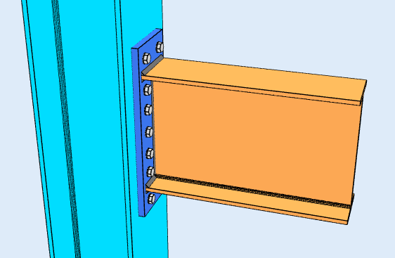
Collegamento della piastra terminale estesa, un esempio di connessione momentanea. I bulloni all'esterno della flangia di tensione conferiscono alla coppia un braccio di leva più lungo.
Lo scopo di a momento di connessione è mantenere la rotazione finale, che in termini di analisi è il codice di fissità FFFFFF: trattenuto in tutte e tre le traduzioni e in tutte e tre le rotazioni. Ecco perché le connessioni momento sono anche chiamate connessioni rigide.
AISC 360-16 La sezione B3.4 è più precisa al riguardo, e la distinzione conta quando modelli la cornice. Neanche un secondo collegamento completamente trattenuto (FR), che mantiene l'angolo tra i membri e giustifica l'ipotesi FFFFFF, o parzialmente trattenuto (PR), che trasferisce il momento ma ruota abbastanza da far sì che l’analisi debba tenere conto della reale rigidezza del giunto. Trattare un giunto PR come completamente rigido sovrastima la rigidità del telaio e ne sottovaluta la deriva.
Dove a connessione a taglio funziona principalmente attraverso l'anima della trave, una connessione momentanea deve impegnare le flange, perché è lì che si trova lo stress da flessione. Piastre flangiate, le flange saldate o una piastra terminale svolgono tutte lo stesso lavoro: trasformano il momento della trave in una forza di tensione in una flangia e in una forza di compressione nell'altra, e porta quella coppia nella colonna.
Tipi di connessione del momento
Le connessioni momento portano molto più momento di una connessione a taglio, e costano di più da realizzare: più materiale, più saldature, più adattamento e più ispezione. La maggior parte dei telai li utilizza solo laddove la struttura si affida all'azione del telaio per la stabilità laterale, e utilizzare connessioni a taglio ovunque.
Le configurazioni disponibili dipendono dal codice di progettazione e dal tipo di struttura della trave.
Trave su colonna con sezione a I (AISC 360-16)
Quattro configurazioni, intelaiatura alla flangia della colonna o all'anima della colonna.
Flangia Piastra
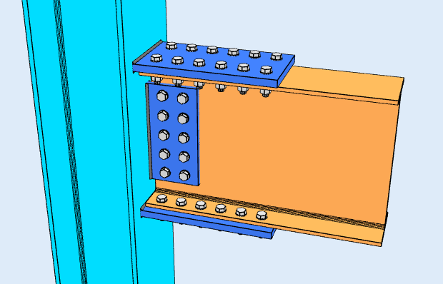
Le piastre corrono attraverso le ali superiore e inferiore della trave, imbullonati o saldati alla trave e alla colonna. Mentre la trave si piega, una piastra va in tensione e l'altra in compressione, e quella coppia porta il momento. L'anima della trave è solitamente sostenuta da una piastra di taglio separata, quindi la connessione divide il lavoro: le flange prendono il momento, il web prende il taglio.
Flange saldate
Le flange della trave sono saldate direttamente alla flangia della colonna, senza piastra intermedia, e l'anima è imbullonata a un piatto di taglio. Ciò garantisce la giunzione più rigida del gruppo e il percorso di carico più pulito, ma è la saldatura sul campo su un membro che deve rientrare nella tolleranza, quindi trasporta il preriscaldamento, costi di accesso e ispezione che un dettaglio imbullonato non comporta.
Piastra terminale a filo
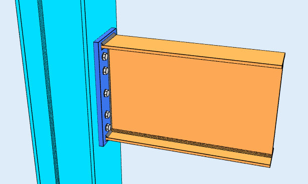
Una piastra saldata all'estremità della trave e imbullonata alla colonna, con la piastra che termina a filo con le flange della trave e tutti i bulloni che si trovano tra di loro. Si adatta ai momenti più bassi, perché il braccio di leva del gruppo otturatore è limitato dalla profondità della trave.
Piastra terminale estesa
La stessa idea, con la piastra estesa oltre la flangia di tensione in modo che i bulloni possano posizionarsi all'esterno di essa. Quei bulloni esterni hanno un braccio di leva più lungo attorno alla flangia di compressione, che è ciò che acquista la capacità del momento extra. L'azione di leva sulla parte estesa diventa un controllo governativo. È la configurazione mostrata nella parte superiore di questa pagina.
Entrambe le configurazioni della piastra terminale sono coperte da calcolatore della connessione momento.
Trave su colonna HSS (AISC 360-16)
Inquadrare una connessione momento in una sezione cava è più difficile, perché non c'è alcuna flangia da imbullonare e nessun accesso al lato opposto. È disponibile una configurazione: un carico piastra flangiata saldato alla faccia dell'HSS, senza irrigidimenti.
AS 4100:2020
AS 4100 la copertura in SkyCiv Connection Design è solo connessioni a taglio, trave d'intelaiatura su colonna con sezione a I o trave su trave. Connessioni momentanee ad AS 4100 non sono disponibili. Per il momento di progettazione, utilizzare AISC 360-16.
Cosa controlla il software?
I dettagli vengono eseguiti per primi: distanze dal bordo dei bulloni, distanza tra i bulloni (passo e calibro), giochi degli strumenti, dimensioni minime e massime della piastra, e rilevamento delle collisioni tra le piastre, rinforzi, bulloni e saldature. Una connessione che non può essere costruita non raggiunge la soluzione.
I controlli di forza seguono poi la coppia attraverso l'articolazione. Sul lato flangia ciò significa la piastra in tensione e in compressione, taglio dei bulloni, cuscinetto e strappo del bullone, rottura per taglio del blocco, azione di leva sui bulloni, e saldare lo stress della gola. Sull'elemento portante significa flessione locale della flangia, cedevolezza del web locale e paralizzante del web, quali sono gli stati limite che decidono se la colonna necessita di irrigidimenti o di una piastra raddoppiatrice.
Ogni formula, il controllo del progetto e il riferimento al codice sono mostrati per intero, con i numeri delle clausole dell'AISC 360-16, in modo da poter seguire il calcolo anziché fidarsi.
Connessione Moment vs Connessione Shear: la differenza
La differenza è ciò che accade all'angolo tra i due membri. In una connessione momentanea quell'angolo viene mantenuto, quindi piegarsi in un membro porta nell'altro. In una connessione a taglio il giunto è libero di ruotare, quindi l'estremità della trave gira e nessun momento significativo attraversa il giunto.
| Connessione momentanea | Connessione a taglio | |
|---|---|---|
| Forze trasferite | Taglio e momento | Solo taglio |
| Nomi alternativi | Rigido, Fisso, Resistente al momento | Appuntato, Cerniera, Semplice |
| AISC 360-16 termine | Connessione a momento FR o PR | Connessione semplice |
| Rotazione | Limita la rotazione | Libero di ruotare |
| Codice di fissità del software | FFFFFF | FFFFFR |
Software di progettazione della connessione SkyCiv
I modelli e i controlli di cui sopra provengono da Progettazione di connessioni SkyCiv. Copre 80+ tipi di connessione preconfigurati, progetta a AISC 360-16 in LRFD e ASD e a AS 4100:2020, e mostra ogni formula, controllo del progetto e riferimento del codice completo.
È possibile modellare la connessione in 3D, scambiare i bulloni, saldature o piastre senza perdere i dati di carico, produrre fogli di disegno di dettaglio 2D in CloudCAD, ed esportare la geometria 3D in IFC per il coordinamento in Revit, Tekla o Navisworks.
Funziona interamente nel browser, senza download, aggiornamenti o configurazione IT.
