
Single angle connection design to AISC 360 means checking one angle, two bolt groups and the beam end against the beam reaction. On the beam side you check bolt shear, bearing and tear-out on the angle and the beam web, blokschaar, shear yielding and rupture of the angle, and angle flexure. If the beam is coped, you also check the coped web for block shear, afschuiving en buiging. On the support side you repeat the bolt and angle checks for the leg bolted to the girder, where the bolt group has to carry the eccentricity of the reaction. Detailing limits on spacing, rand afstand, gage, cope depth and connection depth apply throughout.
This page works one real example from start to finish: a W12x14 beam, coped at the top flange, framing into the web of a W18x35 girder with a 20 kip LRFD reaction, through a single L4x3x3/8 angle with two rows of 3/4 in A325-N bolts on each leg. The design is to AISC 360-16 and the AISC Manual 15th Edition. Every equation is written out with its numbers, in the same order as the AISC calc sheet that the SkyCiv-verbindingsontwerp module produces for this connection.
What is a single angle connection?
A single angle connection is one steel angle on one side of the beam web, with one leg bolted (or welded) to the web and the other leg bolted to the supporting member. It transfers the beam’s end shear and is classified as a simple connection under AISC 360-16 B3.4, so the angle is detailed to flex rather than resist moment.
It is a afschuifverbinding used for lighter reactions, and where only one side of the beam web can be reached, such as beams framing into a girder web next to another member. Because there is only one angle, the beam-side bolts are in single shear and the load reaches the support off to one side of the beam web, so the support bolts have to carry that eccentricity. The other options for the same job are the double angle connection, de enkele plaat (shear tab) verbinding and the shear end plate connection. You can check this example directly in the single angle connection calculator.
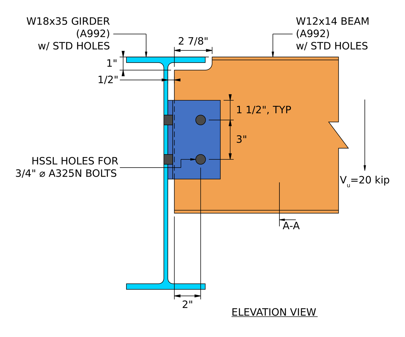
Elevation of the example connection. The beam is coped 2 7/8 in long and 1 in deep at the top to clear the girder flange, met een 1/2 in clearance between the beam end and the girder web.
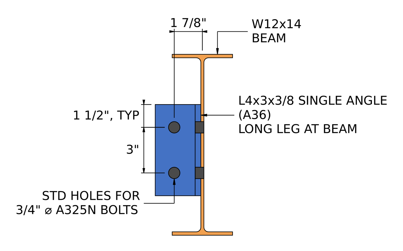
Section A-A. The long leg is bolted to the beam web, als de 3 in outstanding leg is bolted to the girder web.
How do you design a single angle connection? The steps at a glance
- Check the detailing limits at the beam side: spatiëring, randafstanden, diepte, gage, omgaan met.
- Check the beam-side bolt group in single shear.
- Check bolt bearing and tear-out on the angle at the beam side.
- Check bolt bearing and tear-out on the beam web.
- Combine shear, bearing and tear-out per bolt at the beam side.
- Check block shear of the angle at the beam side.
- Check shear yielding and shear rupture of the angle at the beam side.
- Check angle flexure at the beam side using the double coped procedure.
- Check shear and moment interaction of the angle at the beam side.
- Check block shear of the coped beam web.
- Check shear yielding and shear rupture of the coped beam.
- Check flexure of the coped beam.
- Check the detailing limits at the support side.
- Check the support-side bolt group with ICOR for its eccentricity.
- Check bolt bearing and tear-out on the angle at the support side.
- Check bolt bearing on the girder web.
- Combine shear, bearing and tear-out per bolt at the support side.
- Check block shear of the angle at the support side.
- Check shear yielding and shear rupture of the angle at the support side.
- Check angle flexure at the support side using the double coped procedure.
- Check shear and moment interaction of the angle at the support side.
Design inputs for this example
The design code is AISC 360-16 LRFD. Section properties are from the AISC Manual.
| Item | Symbool | Waarde |
|---|---|---|
| Factored vertical shear | [mathin] V_{u} [mathin] | 20 kip |
| Straal | B12x14, A992 | |
| Beam depth | [mathin] d_{bm} [mathin] | 11.9 in |
| Beam web thickness | [mathin] t_{wb} [mathin] | 0.2 in |
| Beam flange width / dikte | [mathin] b_{fb},\ t_{fb} [mathin] | 3.97 in / 0.225 in |
| Beam area | [mathin] A_{bm} [mathin] | 4.16 in² |
| Beam yield / trekspanning | [mathin] F_{yb},\ F_{ub} [mathin] | 50 KSI / 65 KSI |
| Top cope length / diepte | [mathin] L_{ct},\ D_{ct} [mathin] | 2.875 in / 1 in |
| Girder | W18x35, A992 | |
| Girder depth / web thickness | [mathin] d_{sup},\ t_{ws} [mathin] | 17.7 in / 0.3 in |
| Girder flange width / dikte | [mathin] b_{fs},\ t_{fs} [mathin] | 6 in / 0.425 in |
| Girder area | [mathin] A_{sup} [mathin] | 10.3 in² |
| Girder yield / trekspanning | [mathin] F_{ys},\ F_{us} [mathin] | 50 KSI / 65 KSI |
| Modulus of elasticity | [mathin] E [mathin] | 29000 KSI |
| Item | Symbool | Waarde |
|---|---|---|
| Hoek | L4x3x3/8, A36, long leg at beam | |
| Angle depth | [mathin] d_{a} [mathin] | 6 in |
| Angle thickness | [mathin] t_{a} [mathin] | 0.375 in |
| Leg width at beam / at support | [mathin] b_{a,NSL},\ b_{a,OSL} [mathin] | 4 in / 3 in |
| Angle yield / trekspanning | [mathin] F_{ya},\ F_{ua} [mathin] | 36 KSI / 58 KSI |
| Bouten (both sides) | 3/4 in A325-N | |
| Diameter bout | [mathin] d_{b} [mathin] | 0.75 in |
| Bolt nominal tensile / schuifspanning | [mathin] F_{nt},\ F_{nv} [mathin] | 90 KSI / 54 KSI |
| Shear planes, beam side / support side | [mathin] N_{s} [mathin] | 1 / 1 |
| Holes at beam side (hoek / balk) | Short-slotted horizontal (HSSL) / Slankheidsverhouding voor Axial (soa) | |
| Holes at support side (hoek / girder) | Standaard (soa) / Slankheidsverhouding voor Axial (soa) |
| Geometrie | Symbool | Beam side | Support side |
|---|---|---|---|
| Bolt rows / row spacing | [mathin] n_{r},\ s_{r} [mathin] | 2 / 3 in | 2 / 3 in |
| Bolt columns / column spacing | [mathin] n_{c},\ s_{c} [mathin] | 1 / 0 in | 1 / 0 in |
| Gage | [mathin] g [mathin] | 2.5 in | 1.75 in |
| Vertical edge distance on angle | [mathin] L_{ev,a} [mathin] | 1.5 in | 1.5 in |
| Horizontal edge distance on angle | [mathin] L_{eh,a} [mathin] | 1.5 in | 1.25 in |
| Vertical edge distance at beam web | [mathin] L_{ev,bm} [mathin] | 3.575 in | |
| Bolt eccentricity | [mathin] e [mathin] | 2.5 in | 1.85 in |
| Beam web clearance to girder | [mathin] clr [mathin] | 0.5 in |
Stap 1: Detailing limits at the beam side (AISC 360-16 J3.3, J3.4, J3.5)
Before any strength check, the bolt layout has to be buildable and match the assumptions behind the strength equations. Bolts that are too close tear between the holes, edges that are too close tear out, and an angle that is too short or too deep changes how the connection rotates. The cope has to be deep enough to clear the girder flange.
Voor een 3/4 in bolt the minimum spacing is [mathin] 2\tfrac{2}{3} d_{b} = 2\,in [mathin] (J3.3) and the minimum edge distance is 1 in (Table J3.4). The beam-side leg has horizontal short-slotted holes, and the horizontal edge distance on the angle is measured across the end of the slot, so the Table J3.5 increment of 1/8 in for a short slot raises its minimum to 1.125 in. The horizontal edge distance on the beam web is the gage less the clearance, [mathin] 2.5\,in – 0.5\,in = 2\,in [mathin]. The angle has to be at least half as deep as the beam’s T dimension, so it is stiff enough to brace the beam end, and no deeper than the beam web can take. The bolt gage on the beam-side leg has to leave room to enter and tighten the bolts.
| Detailing limit | Limit (in) | Werkelijk (in) | DCR | Resultaat |
|---|---|---|---|---|
| Minimum bolt row spacing | 2.000 | 3.000 | 0.667 | DOORGANG |
| Maximum bolt row spacing | 6.000 | 3.000 | 0.500 | DOORGANG |
| Angle minimum vertical edge distance | 1.000 | 1.500 | 0.667 | DOORGANG |
| Angle minimum horizontal edge distance | 1.125 | 1.500 | 0.750 | DOORGANG |
| Beam minimum vertical edge distance | 1.000 | 3.575 | 0.280 | DOORGANG |
| Beam minimum horizontal edge distance | 1.000 | 2.000 | 0.500 | DOORGANG |
| Minimum connection depth | 5.188 | 6.000 | 0.865 | DOORGANG |
| Maximum connection depth | 10.000 | 6.000 | 0.600 | DOORGANG |
| Minimum bolt gage for single angle | 1.500 | 2.500 | 0.600 | DOORGANG |
| Minimum top cope depth | 0.750 | 1.000 | 0.750 | DOORGANG |
For a minimum limit the ratio is limit over actual, and for a maximum it is actual over limit. The governing row is the minimum connection depth, half the 10 3/8 in T dimension of the W12x14:
[math] DCR = \frac{d}{c} = \frac{(5.1875)}{(6)} = 0.86458 [math]
DCR = 0.865 < 1.0, OK
Stap 2: Bolt group shear at the beam side (AISC 360-16 J3.6)
Each beam-side bolt passes through the angle and the beam web only, so it has one shear plane. The two bolts have to carry the full reaction between them.
Bolt group coefficient
The beam-side bolt line is 2.5 in from the angle heel, but the eccentricity is ignored here. AISC Manual page 10-116 allows this for a single vertical row of bolts with an eccentricity of no more than 3 in, so the bolt group coefficient is simply the number of bolts:
[math] C = 2 [math]
Bolt group strength
Waarbij [mathin] \phi = 0.75 [mathin], [mathin] d_{b} = 0.75\,in [mathin], [mathin] F_{nv} = 54\,ksi [mathin] for an A325-N bolt with threads included, [mathin] N_{s} = 1 [mathin] en [mathin] h_{f} = 1 [mathin] because there are no fillers (J5.2(een)):
[math] \phi R_{n} = \phi\, F_{nv}\, \frac{\pi}{4} \left( d_{b} \right)^{2} N_{s}\, C\, h_{f} [math]
[math] \phi R_{n} = (0.75) \times (54\,ksi) \times \frac{\pi}{4} \times \left( (0.75\,in) \right)^{2} \times (1) \times (2) \times (1) [math]
[math] \phi R_{n} = 35.785\,kip [math]
DCR = 20 kip / 35.785 kip = 0.559 < 1.0, OK
Stap 3: Bolt bearing and tear-out on the single angle at the beam side (AISC 360-16 J3.10)
Each beam-side bolt pushes on the edge of its hole in the angle. The angle either deforms at the hole (lager, capped at 2.4 d t Fu) or tears a strip out to the next hole or to its lower edge (tear-out, 1.2 lc t Fu). The beam pushes the bolts down on the angle, so the bottom bolt, nearest the angle’s lower edge, is the weak one.
The holes are short slots running horizontally and the load is vertical, so the hole dimension in the direction of the load is the standard [mathin] d_{h} = 0.8125\,in [mathin]. Clear distance for the edge bolt, met [mathin] L_{ev,a} = 1.5\,in [mathin]:
[math] l_{c1} = L_{ev,a} – \frac{d_{h}}{2} = (1.5\,in) – \frac{(0.8125\,in)}{2} = 1.0938\,in [math]
Clear distance between bolts, met [mathin] s_{r} = 3\,in [mathin]:
[math] l_{c2} = s_{r} – d_{h} = (3\,in) – (0.8125\,in) = 2.1875\,in [math]
Waarbij [mathin] t_{a} = 0.375\,in [mathin], [mathin] F_{ua} = 58\,ksi [mathin], [mathin] C = 2 [mathin] en [mathin] n_{r} = 2 [mathin]:
[math] \phi R_{n} = \phi \left[ \min\left(1.2\, l_{c1},\, 2.4\, d_{b}\right) t_{a} F_{ua} + \min\left(1.2\, l_{c2},\, 2.4\, d_{b}\right) t_{a} F_{ua} \left( n_{r} – 1 \right) \right] \left( \frac{C}{n_{r}} \right) [math]
[math] \phi R_{n} = (0.75) \times \left[ \min\left(1.2 \times (1.0938\,in),\, 2.4 \times (0.75\,in)\right) \times (0.375\,in) \times (58\,ksi) + \min\left(1.2 \times (2.1875\,in),\, 2.4 \times (0.75\,in)\right) \times (0.375\,in) \times (58\,ksi) \times \left( (2) – 1 \right) \right] \times \left( \frac{(2)}{(2)} \right) [math]
[math] \phi R_{n} = 50.773\,kip [math]
DCR = 20 kip / 50.773 kip = 0.394 < 1.0, OK
Tear-out governs the edge bolt, because 1.2 lc1 is less than 2.4 db. The other bolt is limited by bearing.
Stap 4: Bolt bearing and tear-out on the beam web (AISC 360-16 J3.10)
The same check applies to the beam web. Here the web moves down against bolts held by the angle, so the bolts bear on the top of the web holes, and the edge bolt is the top one, 3.575 in below the cut edge of the cope.
Clear distance for the top bolt, met [mathin] L_{ev,bm} = 3.575\,in [mathin] en [mathin] d_{h} = 0.8125\,in [mathin]:
[math] l_{c1} = L_{ev,bm} – \frac{d_{h}}{2} = (3.575\,in) – \frac{(0.8125\,in)}{2} = 3.1688\,in [math]
[math] l_{c2} = s_{r} – d_{h} = (3\,in) – (0.8125\,in) = 2.1875\,in [math]
Waarbij [mathin] t_{wb} = 0.2\,in [mathin], [mathin] F_{ub} = 65\,ksi [mathin], [mathin] C = 2 [mathin] en [mathin] n_{r} = 2 [mathin]:
[math] \phi R_{n} = \phi \left[ \min\left(1.2\, l_{c1},\, 2.4\, d_{b}\right) t_{wb} F_{ub} + \min\left(1.2\, l_{c2},\, 2.4\, d_{b}\right) t_{wb} F_{ub} \left( n_{r} – 1 \right) \right] \left( \frac{C}{n_{r}} \right) [math]
[math] \phi R_{n} = (0.75) \times \left[ \min\left(1.2 \times (3.1688\,in),\, 2.4 \times (0.75\,in)\right) \times (0.2\,in) \times (65\,ksi) + \min\left(1.2 \times (2.1875\,in),\, 2.4 \times (0.75\,in)\right) \times (0.2\,in) \times (65\,ksi) \times \left( (2) – 1 \right) \right] \times \left( \frac{(2)}{(2)} \right) [math]
[math] \phi R_{n} = 35.1\,kip [math]
DCR = 20 kip / 35.1 kip = 0.570 < 1.0, OK
Both bolts are capped by bearing at 2.4 db, because the long edge distance below the cope keeps tear-out out of play. De 0.2 in web is thinner than the 3/8 in angle, so it is the weaker ply on the beam side.
Stap 5: Effective strength of the bolt group at the beam side (AISC 360-16 J3.6 Commentary)
Bout afschuiving, bearing and tear-out are not really separate checks. Each bolt carries the least of its shear strength and its bearing or tear-out strength in every ply it passes through, and the group strength is the sum of those per-bolt values.
Strength of one bolt in single shear:
[math] \phi r_{v} = \phi\, F_{nv}\, \frac{\pi}{4} \left( d_{b} \right)^{2} N_{s}\, h_{f} = (0.75) \times (54\,ksi) \times \frac{\pi}{4} \times \left( (0.75\,in) \right)^{2} \times (1) \times (1) = 17.892\,kip [math]
Bearing and tear-out of one bolt on the angle, for the edge bolt and the inner bolt:
[math] \phi r_{n1e} = \phi\, \min\left(1.2\, l_{c1},\, 2.4\, d_{b}\right) t_{a} F_{ua} = (0.75) \times \min\left(1.2 \times (1.0938\,in),\, 2.4 \times (0.75\,in)\right) \times (0.375\,in) \times (58\,ksi) = 21.41\,kip [math]
[math] \phi r_{n1i} = \phi\, \min\left(1.2\, l_{c2},\, 2.4\, d_{b}\right) t_{a} F_{ua} = (0.75) \times \min\left(1.2 \times (2.1875\,in),\, 2.4 \times (0.75\,in)\right) \times (0.375\,in) \times (58\,ksi) = 29.363\,kip [math]
Bearing and tear-out of one bolt on the beam web, for the edge bolt and the inner bolt:
[math] \phi r_{n2e} = \phi\, \min\left(1.2\, l_{c1},\, 2.4\, d_{b}\right) t_{wb} F_{ub} = (0.75) \times \min\left(1.2 \times (3.1688\,in),\, 2.4 \times (0.75\,in)\right) \times (0.2\,in) \times (65\,ksi) = 17.55\,kip [math]
[math] \phi r_{n2i} = \phi\, \min\left(1.2\, l_{c2},\, 2.4\, d_{b}\right) t_{wb} F_{ub} = (0.75) \times \min\left(1.2 \times (2.1875\,in),\, 2.4 \times (0.75\,in)\right) \times (0.2\,in) \times (65\,ksi) = 17.55\,kip [math]
Bolts are numbered from the top of the line. Bout 1 is the edge bolt on the beam web and an inner bolt on the angle; Bout 2 is the edge bolt on the angle:
[math] \phi r_{eff,1} = \min\left( \phi r_{v},\, \phi r_{n1i},\, \phi r_{n2e} \right) = \min\left( (17.892\,kip),\, (29.363\,kip),\, (17.55\,kip) \right) = 17.55\,kip [math]
[math] \phi r_{eff,2} = \min\left( \phi r_{v},\, \phi r_{n1e},\, \phi r_{n2i} \right) = \min\left( (17.892\,kip),\, (21.41\,kip),\, (17.55\,kip) \right) = 17.55\,kip [math]
| Bout | Bout afschuiving (kip) | Met de laatste knop in het menu aan de linkerkant kunt u de waarde van de toeslag wijzigen / tear-out, enkele hoek (kip) | Met de laatste knop in het menu aan de linkerkant kunt u de waarde van de toeslag wijzigen / tear-out, beam web (kip) | Effective strength (kip) |
|---|---|---|---|---|
| 1 | 17.89 | 29.36 | 17.55 | 17.55 |
| 2 | 17.89 | 21.41 | 17.55 | 17.55 |
[math] \sum \phi r_{eff} = n_{1}\, \phi r_{eff,1} + n_{2}\, \phi r_{eff,2} = (1) \times (17.55\,kip) + (1) \times (17.55\,kip) = 35.1\,kip [math]
[math] \phi R_{n,eff} = \left( \frac{C}{n_{r}} \right) \sum \phi r_{eff} = \left( \frac{(2)}{(2)} \right) \times (35.1\,kip) = 35.1\,kip [math]
DCR = 20 kip / 35.1 kip = 0.570 < 1.0, OK
Bearing on the beam web governs both bolts, though bolt shear is only 2% higher. You can run the same connection in the free connection design calculator and try a third bolt row to see how the ratio moves.
Stap 6: Block shear of the single angle at the beam side (AISC 360-16 J4.3)
A block of the angle can tear out along the bolt line: shear down the line of holes, plus tension across to the angle’s free edge. With one bolt column this is an L-shaped block.
Net area in tension. The tension plane runs horizontally, along the slots, so it uses the slot length [mathin] d_{h} = 1\,in [mathin], met [mathin] t_{a} = 0.375\,in [mathin], [mathin] n_{c} = 1 [mathin], [mathin] s_{c} = 0\,in [mathin] en [mathin] L_{eh,a} = 1.5\,in [mathin]. Each hole adds 1/16 in for damage during punching (B4.3):
[math] A_{nt} = t_{a} \left[ (n_{c}-1)\, s_{c} + L_{eh,a} – (n_{c} – 0.5)\left( d_{h} + 0.0625\,in \right) \right] [math]
[math] A_{nt} = (0.375\,in) \times \left[ ((1)-1) \times (0\,in) + (1.5\,in) – ((1) – 0.5) \times ((1\,in) + (0.0625\,in)) \right] = 0.36328\,in^{2} [math]
Gross and net areas in shear. The shear plane runs vertically, across the slots, so it uses [mathin] d_{h} = 0.8125\,in [mathin]:
[math] A_{gv} = t_{a} \left[ L_{ev,a} + (n_{r}-1)\, s_{r} \right] = (0.375\,in) \times \left[ (1.5\,in) + ((2)-1) \times (3\,in) \right] = 1.6875\,in^{2} [math]
[math] A_{nv} = t_{a} \left[ d_{a} – L_{ev,a} – (n_{r} – 0.5)\left( d_{h} + 0.0625\,in \right) \right] [math]
[math] A_{nv} = (0.375\,in) \times \left[ (6\,in) – (1.5\,in) – ((2) – 0.5) \times ((0.8125\,in) + (0.0625\,in)) \right] = 1.1953\,in^{2} [math]
Block shear strength, met [mathin] U_{bs} = 1 [mathin] for uniform tension, [mathin] F_{ua} = 58\,ksi [mathin], [mathin] F_{ya} = 36\,ksi [mathin] en [mathin] \phi = 0.75 [mathin]:
[math] \phi R_{n} = \phi \left( 0.6\, F_{ua} A_{nv} + U_{bs} F_{ua} A_{nt} \le 0.6\, F_{ya} A_{gv} + U_{bs} F_{ua} A_{nt} \right) [math]
[math] \phi R_{n} = (0.75) \times \left( 0.6 \times (58\,ksi) \times (1.1953\,in^{2}) + (1) \times (58\,ksi) \times (0.36328\,in^{2}) \le 0.6 \times (36\,ksi) \times (1.6875\,in^{2}) + (1) \times (58\,ksi) \times (0.36328\,in^{2}) \right) [math]
[math] \phi R_{n} = 43.14\,kip [math]
DCR = 20 kip / 43.14 kip = 0.464 < 1.0, OK
The shear yielding side of the equation governs. A36 has a low yield-to-tensile ratio, so the gross shear plane yields before the net shear plane ruptures.
Stap 7: Shear yielding and shear rupture of the single angle at the beam side (AISC 360-16 J4.2)
The full reaction passes down through the angle leg as vertical shear. The gross section must not yield, and the net section through the bolt holes must not rupture.
Shear yielding (Eq. J4-3)
[math] A_{gv} = d_{a}\, t_{a} = (6\,in) \times (0.375\,in) = 2.25\,in^{2} [math]
[math] \phi R_{n,sy} = \phi\, 0.6\, F_{ya} A_{gv} = (1) \times 0.6 \times (36\,ksi) \times (2.25\,in^{2}) = 48.6\,kip [math]
Shear rupture (Eq. J4-4)
[math] A_{nv} = t_{a} \left[ d_{a} – n_{r}\left( d_{h} + 0.0625\,in \right) \right] = (0.375\,in) \times \left[ (6\,in) – (2) \times ((0.8125\,in) + (0.0625\,in)) \right] = 1.5938\,in^{2} [math]
[math] \phi R_{n,sr} = \phi\, 0.6\, F_{ua} A_{nv} = (0.75) \times 0.6 \times (58\,ksi) \times (1.5938\,in^{2}) = 41.597\,kip [math]
[math] \phi R_{n} = \min\left( \phi R_{n,sy},\, \phi R_{n,sr} \right) = \min\left( (48.6\,kip),\, (41.597\,kip) \right) = 41.597\,kip [math]
DCR = 20 kip / 41.597 kip = 0.481 < 1.0, OK
Stap 8: Flexure of the single angle at the beam side, double coped procedure (AISC 360-16 F11.2)
The reaction is carried from the beam-side bolt line to the heel of the angle, so the leg acts as a short cantilever plate in bending. Een diep, thin leg can buckle sideways before it yields. The AISC Manual handles this with the procedure for a beam coped at both flanges, treating the leg like a beam web with the flanges cut away. The unbraced length is the beam-side gage, [mathin] L_{b} = 2.5\,in [mathin]. The leg is also checked for flexural rupture through the bolt holes.
Range check
Waarbij [mathin] E = 29000\,ksi [mathin], [mathin] F_{ya} = 36\,ksi [mathin], [mathin] d_{a} = 6\,in [mathin] en [mathin] t_{a} = 0.375\,in [mathin]:
[math] \frac{L_{b} d}{t^{2}} = \frac{(2.5\,in) \times (6\,in)}{(0.375\,in)^{2}} = 106.67 [math]
[math] \frac{0.08 E}{F_{y}} = \frac{0.08 \times (29000\,ksi)}{(36\,ksi)} = 64.444 \qquad \frac{1.9 E}{F_{y}} = \frac{1.9 \times (29000\,ksi)}{(36\,ksi)} = 1530.6 [math]
Dus [mathin] \frac{0.08E}{F_{y}} \lt \frac{L_{b} d}{t^{2}} \le \frac{1.9E}{F_{y}} [mathin], Stapelcapaciteit schatten. F11-2 applies.
Section moduli of the angle leg
[math] Z = \frac{t_{a} \left( d_{a} \right)^{2}}{4} = \frac{(0.375\,in) \times ((6\,in))^{2}}{4} = 3.375\,in^{3} [math]
[math] S = \frac{t_{a} \left( d_{a} \right)^{2}}{6} = \frac{(0.375\,in) \times ((6\,in))^{2}}{6} = 2.25\,in^{3} [math]
Lateral-torsional buckling modification factor (AISC Manual Eq. 9-15)
With no cope on the angle, [mathin] d_{ct} = 0\,in [mathin]:
[math] C_{b} = \left[ 3 + \ln\left( \frac{L_{b}}{d_{a}} \right) \right] \left( 1 – \frac{d_{ct}}{d_{a}} \right) \ge 1.84 [math]
[math] C_{b} = \left[ 3 + \ln\left( \frac{(2.5\,in)}{(6\,in)} \right) \right] \times \left( 1 – \frac{(0\,in)}{(6\,in)} \right) \ge 1.84 [math]
[math] C_{b} = 2.1245 [math]
Flexural yielding and buckling strength
Met [mathin] \phi = 0.9 [mathin]:
[math] \phi M_{n} = \phi \left[ C_{b} \left[ 1.52 – 0.274 \left( \frac{L_{b} d}{t^{2}} \right) \left( \frac{F_{ya}}{E} \right) \right] F_{ya} S \le F_{ya} Z \right] [math]
[math] \phi M_{n} = (0.9) \times \left[ (2.1245) \times \left[ 1.52 – 0.274 \times ((106.67)) \times \left( \frac{(36\,ksi)}{(29000\,ksi)} \right) \right] \times (36\,ksi) \times (2.25\,in^{3}) \le (36\,ksi) \times (3.375\,in^{3}) \right] [math]
[math] \phi M_{n} = 9.1125\,kip\text{-}ft \;(109.35\,kip\text{-}in) [math]
The plastic moment cap [mathin] F_{ya} Z [mathin] governs, so the leg is not prone to buckling at this depth and thickness. The equivalent shear capacity is:
[math] \phi V_{n,y} = \frac{\phi M_{n}}{L_{b}} = \frac{(9.1125\,kip\text{-}ft)}{(2.5\,in)} = 43.74\,kip [math]
Flexural rupture (AISC Manual Part 15 Tafel 15-3, Een deel 9 Eq. 9-4)
The net plastic section modulus removes the bolt holes, met [mathin] d_{h} = 0.8125\,in [mathin] en [mathin] s_{r} = 3\,in [mathin]. With an even number of rows the last term is zero:
[math] Z_{net} = \frac{t_{a} \left( d_{a} \right)^{2}}{4} – t_{a} \left( d_{h} + 0.0625\,in \right) s_{r} \left\lfloor \frac{n_{r}^{2}}{4} \right\rfloor – \left[ n_{r}\ \text{odd} \right] \frac{t_{a} \left( d_{h} + 0.0625\,in \right)^{2}}{4} [math]
[math] Z_{net} = \frac{(0.375\,in) \times ((6\,in))^{2}}{4} – (0.375\,in) \times ((0.8125\,in) + (0.0625\,in)) \times (3\,in) \times \left\lfloor \frac{(2)^{2}}{4} \right\rfloor – \left[ (2)\ \text{odd} \right] \times \frac{(0.375\,in) \times ((0.8125\,in) + (0.0625\,in))^{2}}{4} = 2.3906\,in^{3} [math]
[math] \phi M_{n} = \phi\, F_{ua} Z_{net} = (0.75) \times (58\,ksi) \times (2.3906\,in^{3}) = 8.666\,kip\text{-}ft [math]
[math] \phi V_{n,r} = \frac{\phi M_{n}}{L_{b}} = \frac{(8.666\,kip\text{-}ft)}{(2.5\,in)} = 41.597\,kip [math]
Governing flexural capacity
[math] \phi V_{n} = \min\left( \phi V_{n,y},\, \phi V_{n,r} \right) = \min\left( (43.74\,kip),\, (41.597\,kip) \right) = 41.597\,kip [math]
DCR = 20 kip / 41.597 kip = 0.481 < 1.0, OK
Flexural rupture governs. It happens to give the same 41.597 kip as shear rupture in Step 7.
Stap 9: Shear and moment interaction of the single angle at the beam side (AISC Manual Eq. 10-5)
The angle leg carries shear and bending at the same section at the same time, so the two have to be checked together. The Manual uses a circular interaction between the shear yielding strength and the flexural strength.
The moment at the angle is the reaction times the unbraced length, met [mathin] V_{r} = 20\,kip [mathin] en [mathin] L_{b} = 2.5\,in [mathin]:
[math] M_{r} = V_{r}\, L_{b} = (20\,kip) \times (2.5\,in) = 4.1667\,kip\text{-}ft [math]
Met [mathin] \phi V_{n} = 48.6\,kip [mathin] from shear yielding in Step 7 en [mathin] \phi M_{n} = 9.1125\,kip\text{-}ft [mathin] from Step 8:
[math] I_{nt} = \left( \frac{V_{r}}{\phi V_{n}} \right)^{2} + \left( \frac{M_{r}}{\phi M_{n}} \right)^{2} [math]
[math] I_{nt} = \left( \frac{(20\,kip)}{(48.6\,kip)} \right)^{2} + \left( \frac{(4.1667\,kip\text{-}ft)}{(9.1125\,kip\text{-}ft)} \right)^{2} = 0.37843 [math]
DCR = 0.37843 / 1.0 = 0.378 < 1.0, OK
Stap 10: Block shear of the coped beam web (AISC 360-16 J4.3)
The top cope removes the beam’s top flange at the connection, so a block of the web can tear out along the bolt line: shear up the line of holes to the cut edge of the cope, plus tension across to the beam end.
Net area in tension, met [mathin] t_{wb} = 0.2\,in [mathin], [mathin] L_{eh,bm} = 2\,in [mathin] and the standard hole [mathin] d_{h} = 0.8125\,in [mathin]:
[math] A_{nt} = t_{wb} \left[ (n_{c}-1)\, s_{c} + L_{eh,bm} – (n_{c} – 0.5)\left( d_{h} + 0.0625\,in \right) \right] [math]
[math] A_{nt} = (0.2\,in) \times \left[ ((1)-1) \times (0\,in) + (2\,in) – ((1) – 0.5) \times ((0.8125\,in) + (0.0625\,in)) \right] = 0.3125\,in^{2} [math]
Gross area in shear, from the cope edge down to the bottom bolt, met [mathin] L_{ev,bm} = 3.575\,in [mathin]:
[math] A_{gv} = t_{wb} \left[ L_{ev,bm} + (n_{r}-1)\, s_{r} \right] = (0.2\,in) \times \left[ (3.575\,in) + ((2)-1) \times (3\,in) \right] = 1.315\,in^{2} [math]
Net area in shear. The report writes it with a depth term [mathin] d_{coped} = 10.15\,in [mathin]; the bracket [mathin] d_{coped} – L_{ev,bm} = 6.575\,in [mathin] is the same shear plane length as in the gross area:
[math] A_{nv} = t_{wb} \left[ d_{coped} – L_{ev,bm} – (n_{r} – 0.5)\left( d_{h} + 0.0625\,in \right) \right] [math]
[math] A_{nv} = (0.2\,in) \times \left[ (10.15\,in) – (3.575\,in) – ((2) – 0.5) \times ((0.8125\,in) + (0.0625\,in)) \right] = 1.0525\,in^{2} [math]
Met [mathin] F_{ub} = 65\,ksi [mathin], [mathin] F_{yb} = 50\,ksi [mathin], [mathin] U_{bs} = 1 [mathin] en [mathin] \phi = 0.75 [mathin]:
[math] \phi R_{n} = \phi \left( 0.6\, F_{ub} A_{nv} + U_{bs} F_{ub} A_{nt} \le 0.6\, F_{yb} A_{gv} + U_{bs} F_{ub} A_{nt} \right) [math]
[math] \phi R_{n} = (0.75) \times \left( 0.6 \times (65\,ksi) \times (1.0525\,in^{2}) + (1) \times (65\,ksi) \times (0.3125\,in^{2}) \le 0.6 \times (50\,ksi) \times (1.315\,in^{2}) + (1) \times (65\,ksi) \times (0.3125\,in^{2}) \right) [math]
[math] \phi R_{n} = 44.822\,kip [math]
DCR = 20 kip / 44.822 kip = 0.446 < 1.0, OK
Stap 11: Shear yielding and shear rupture of the coped beam (AISC 360-16 J4.2)
At the cope, the full reaction passes through the web that is left below the cut, without the top flange. That reduced web is checked for shear yielding on its gross area and shear rupture through the bolt holes.
The depth of web remaining is the beam depth less the cope depth, [mathin] d_{coped} = 11.9\,in – 1\,in = 10.9\,in [mathin].
Shear yielding (Eq. J4-3)
[math] A_{gv} = d_{coped}\, t_{wb} = (10.9\,in) \times (0.2\,in) = 2.18\,in^{2} [math]
[math] \phi R_{n,sy} = \phi\, 0.6\, F_{yb} A_{gv} = (1) \times 0.6 \times (50\,ksi) \times (2.18\,in^{2}) = 65.4\,kip [math]
Shear rupture (Eq. J4-4)
[math] A_{nv} = t_{wb} \left[ d_{coped} – n_{r}\left( d_{h} + 0.0625\,in \right) \right] = (0.2\,in) \times \left[ (10.9\,in) – (2) \times ((0.8125\,in) + (0.0625\,in)) \right] = 1.83\,in^{2} [math]
[math] \phi R_{n,sr} = \phi\, 0.6\, F_{ub} A_{nv} = (0.75) \times 0.6 \times (65\,ksi) \times (1.83\,in^{2}) = 53.528\,kip [math]
[math] \phi R_{n} = \min\left( (65.4\,kip),\, (53.528\,kip) \right) = 53.528\,kip [math]
DCR = 20 kip / 53.528 kip = 0.374 < 1.0, OK
Stap 12: Flexure of the coped beam (AISC Manual Part 9, Eq. 9-7)
The reaction acts at the beam end, so the coped section at the inside face of the cope carries a moment equal to the reaction times its distance from the bolts. Without its top flange the web there is a tee with an unbraced top edge in compression, which can buckle locally. The Manual’s coped beam procedure checks the web slenderness against a limit that depends on the cope geometry.
Ingangen: [mathin] F_{yb} = 50\,ksi [mathin], [mathin] D_{ct} = 1\,in [mathin], [mathin] c = L_{ct} = 2.875\,in [mathin], no bottom cope, [mathin] \phi = 0.9 [mathin]. The section moduli of the tee remaining at the cope are [mathin] S_{x} = 5.6132\,in^{3} [mathin] en [mathin] Z_{x} = 9.5686\,in^{3} [mathin].
Web slenderness (Eq. 9-11)
[math] \lambda = \frac{h_{o}}{t_{wb}} = \frac{(10.9\,in)}{(0.2\,in)} = 54.5 [math]
Buckling adjustment factor (Eq. 9-14een) and plate buckling coefficient (Eq. 9-13een)
Sinds [mathin] c \le d_{bm} [mathin] en [mathin] c \le h_{o} [mathin]:
[math] f = 2 \left( \frac{c}{d_{bm}} \right) = 2 \times \left( \frac{(2.875\,in)}{(11.9\,in)} \right) = 0.48319 [math]
[math] k = 2.2 \left( \frac{h_{o}}{c} \right)^{1.65} = 2.2 \times \left( \frac{(10.9\,in)}{(2.875\,in)} \right)^{1.65} = 19.835 [math]
Limiting slenderness for a compact web (Eq. 9-12)
[math] \lambda_{p} = 0.475 \sqrt{\frac{\left( f k \ge 1.61 \right) E}{F_{yb}}} [math]
[math] \lambda_{p} = 0.475 \times \sqrt{\frac{\left( (0.48319) \times (19.835) \ge 1.61 \right) \times (29000\,ksi)}{(50\,ksi)}} = 35.414 [math]
Flexural strength (Eq. 9-7)
Sinds [mathin] \lambda_{p} \lt \lambda \le 2\lambda_{p} [mathin], the web is noncompact and the strength is interpolated between the plastic and elastic moments:
[math] \phi M_{n} = \phi \left[ F_{yb} Z_{x} – \left( F_{yb} Z_{x} – F_{yb} S_{x} \right) \left( \frac{\lambda}{\lambda_{p}} – 1 \right) \right] [math]
[math] \phi M_{n} = (0.9) \times \left[ (50\,ksi) \times (9.5686\,in^{3}) – \left( (50\,ksi) \times (9.5686\,in^{3}) – (50\,ksi) \times (5.6132\,in^{3}) \right) \times \left( \frac{(54.5)}{(35.414)} – 1 \right) \right] [math]
[math] \phi M_{n} = 27.889\,kip\text{-}ft [math]
Equivalent shear capacity
The lever arm is the cope eccentricity, the cope length plus the beam end clearance, [mathin] e_{c} = 2.875\,in + 0.5\,in = 3.375\,in [mathin]:
[math] \phi V_{n} = \frac{\phi M_{n}}{e_{c}} = \frac{(27.889\,kip\text{-}ft)}{(3.375\,in)} = 99.16\,kip [math]
DCR = 20 kip / 99.16 kip = 0.202 < 1.0, OK
Stap 13: Detailing limits at the support side (AISC 360-16 J3.3, J3.4, J3.5)
The outstanding leg is bolted to the girder web, so the same spacing and edge rules apply, plus a gage limit that keeps the bolts far enough out from the beam web to be entered and tightened. The angle holes here are standard, so the horizontal edge distance minimum is the plain 1 in from Table J3.4. The actual edge distance is what is left of the 3 in leg outside the 1.75 in gage, 1.25 in.
| Detailing limit | Limit (in) | Werkelijk (in) | DCR | Resultaat |
|---|---|---|---|---|
| Minimum bolt row spacing | 2.000 | 3.000 | 0.667 | DOORGANG |
| Maximum bolt row spacing | 6.000 | 3.000 | 0.500 | DOORGANG |
| Angle minimum vertical edge distance | 1.000 | 1.500 | 0.667 | DOORGANG |
| Angle minimum horizontal edge distance | 1.000 | 1.250 | 0.800 | DOORGANG |
| Minimum bolt gage for single angle | 1.500 | 1.750 | 0.857 | DOORGANG |
The governing row is the minimum bolt gage:
[math] DCR = \frac{d}{c} = \frac{(1.5)}{(1.75)} = 0.85714 [math]
DCR = 0.857 < 1.0, OK
Stap 14: Bolt group shear at the support side by the instantaneous center of rotation (AISC 360-16 J3.6)
This is where a single angle differs most from a double angle. The beam web sits to one side of the support bolt line, so the reaction reaches the girder bolts 1.85 in off their line, and the two bolts carry a moment as well as the shear. The instantaneous center of rotation (ICOR) method finds the point the bolt group rotates about and turns that into a coefficient C, the number of bolts’ worth of shear strength the group actually delivers.
Design eccentricity
The eccentricity is the support gage plus half the beam web, measured to the beam web centreline:
[math] e = g + \frac{t_{wb}}{2} = 1.75\,in + \frac{0.2\,in}{2} = 1.85\,in [math]
Strength of one bolt
[math] \phi r_{v} = \phi\, F_{nv}\, \frac{\pi}{4} \left( d_{b} \right)^{2} N_{s}\, h_{f} = 17.892\,kip [math]
Locating the instantaneous center
Bout 1 is at the bottom of the line, with the coordinates below. The IC is found by iteration, using the load-deformation curve of AISC Manual Equation (7-1) op pagina's 7-6 naar 7-8. De bolt group calculation using ICOR walks through that iteration in full.
| Bout | X (in) | j (in) |
|---|---|---|
| 1 | 0.00 | 0.00 |
| 2 | 0.00 | 3.00 |
The iteration converges with the IC at:
[math] x_{ic} = -1.2162\,in, \qquad y_{ic} = 1.5\,in [math]
The bolt reactions at that location are:
| Bout | R (kip) | Rx (kip) | Ry (kip) | Mn (kip-in) |
|---|---|---|---|---|
| 1 | 17.56 | 13.64 | 11.06 | 33.91 |
| 2 | 17.56 | -13.64 | 11.06 | 33.91 |
That gives the bolt group coefficient:
[math] C = 1.24 [math]
Bolt group strength
Met [mathin] N_{s} = 1 [mathin], [mathin] h_{f} = 1 [mathin] (J5.2(een)) en [mathin] \phi = 0.75 [mathin]:
[math] \phi R_{n} = \phi\, F_{nv}\, \frac{\pi}{4} \left( d_{b} \right)^{2} N_{s}\, C\, h_{f} [math]
[math] \phi R_{n} = (0.75) \times (54\,ksi) \times \frac{\pi}{4} \times \left( (0.75\,in) \right)^{2} \times (1) \times (1.24) \times (1) [math]
[math] \phi R_{n} = 22.187\,kip [math]
DCR = 20 kip / 22.187 kip = 0.901 < 1.0, OK
This is the governing check in the connection. With only two bolts 3 in apart, een 1.85 in eccentricity cuts the group from 2 bouten’ worth of strength to 1.24, een 38% verlies.
Stap 15: Bolt bearing and tear-out on the single angle at the support side (AISC 360-16 J3.10)
On the support side the angle is pushed down while the girder web holds the bolts in place, so the bolts bear upward on the angle holes. The top bolt, nearest the angle’s upper edge, is the edge bolt here. The group strength is scaled by C/n to account for the eccentricity.
[math] l_{c1} = L_{ev,a} – \frac{d_{h}}{2} = (1.5\,in) – \frac{(0.8125\,in)}{2} = 1.0938\,in [math]
[math] l_{c2} = s_{r} – d_{h} = (3\,in) – (0.8125\,in) = 2.1875\,in [math]
Waarbij [mathin] t_{a} = 0.375\,in [mathin], [mathin] F_{ua} = 58\,ksi [mathin], [mathin] C = 1.24 [mathin] en [mathin] n_{r} = 2 [mathin]:
[math] \phi R_{n} = \phi \left[ \min\left(1.2\, l_{c1},\, 2.4\, d_{b}\right) t_{a} F_{ua} + \min\left(1.2\, l_{c2},\, 2.4\, d_{b}\right) t_{a} F_{ua} \left( n_{r} – 1 \right) \right] \left( \frac{C}{n_{r}} \right) [math]
[math] \phi R_{n} = (0.75) \times \left[ \min\left(1.2 \times (1.0938\,in),\, 2.4 \times (0.75\,in)\right) \times (0.375\,in) \times (58\,ksi) + \min\left(1.2 \times (2.1875\,in),\, 2.4 \times (0.75\,in)\right) \times (0.375\,in) \times (58\,ksi) \times \left( (2) – 1 \right) \right] \times \left( \frac{(1.24)}{(2)} \right) [math]
[math] \phi R_{n} = 31.479\,kip [math]
DCR = 20 kip / 31.479 kip = 0.635 < 1.0, OK
Stap 16: Bolt bearing on the girder web (AISC 360-16 J3.10)
The bolts also bear on the girder web. The girder runs past the connection in both directions, so there is no edge to tear out to and every bolt bears like an inner bolt.
[math] l_{c2} = s_{r} – d_{h} = (3\,in) – (0.8125\,in) = 2.1875\,in [math]
Waarbij [mathin] t_{ws} = 0.3\,in [mathin], [mathin] F_{us} = 65\,ksi [mathin] en [mathin] C = 1.24 [mathin]:
[math] \phi R_{n} = \phi\, \min\left(1.2\, l_{c2},\, 2.4\, d_{b}\right) t_{ws} F_{us}\, C [math]
[math] \phi R_{n} = (0.75) \times \min\left(1.2 \times (2.1875\,in),\, 2.4 \times (0.75\,in)\right) \times (0.3\,in) \times (65\,ksi) \times (1.24) [math]
[math] \phi R_{n} = 32.643\,kip [math]
DCR = 20 kip / 32.643 kip = 0.613 < 1.0, OK
Stap 17: Effective strength of the bolt group at the support side (AISC 360-16 J3.6 Commentary)
As at the beam side, each bolt delivers the least of its shear strength and its bearing or tear-out strength in each ply, and the group strength is the sum, scaled here by C/n for the eccentricity.
[math] \phi r_{v} = \phi\, F_{nv}\, \frac{\pi}{4} \left( d_{b} \right)^{2} N_{s}\, h_{f} = (0.75) \times (54\,ksi) \times \frac{\pi}{4} \times \left( (0.75\,in) \right)^{2} \times (1) \times (1) = 17.892\,kip [math]
Bearing and tear-out of one bolt on the angle, for the edge bolt and the inner bolt:
[math] \phi r_{n1e} = (0.75) \times \min\left(1.2 \times (1.0938\,in),\, 2.4 \times (0.75\,in)\right) \times (0.375\,in) \times (58\,ksi) = 21.41\,kip [math]
[math] \phi r_{n1i} = (0.75) \times \min\left(1.2 \times (2.1875\,in),\, 2.4 \times (0.75\,in)\right) \times (0.375\,in) \times (58\,ksi) = 29.363\,kip [math]
Bearing of one bolt on the girder web:
[math] \phi r_{n2} = \phi\, \min\left(1.2\, l_{c2},\, 2.4\, d_{b}\right) t_{ws} F_{us} = (0.75) \times \min\left(1.2 \times (2.1875\,in),\, 2.4 \times (0.75\,in)\right) \times (0.3\,in) \times (65\,ksi) = 26.325\,kip [math]
Bolts are numbered from the top of the line, so bolt 1 is the edge bolt on the support side:
[math] \phi r_{eff,1} = \min\left( \phi r_{v},\, \phi r_{n1e},\, \phi r_{n2} \right) = \min\left( (17.892\,kip),\, (21.41\,kip),\, (26.325\,kip) \right) = 17.892\,kip [math]
[math] \phi r_{eff,2} = \min\left( \phi r_{v},\, \phi r_{n1i},\, \phi r_{n2} \right) = \min\left( (17.892\,kip),\, (29.363\,kip),\, (26.325\,kip) \right) = 17.892\,kip [math]
| Bout | Bout afschuiving (kip) | Met de laatste knop in het menu aan de linkerkant kunt u de waarde van de toeslag wijzigen / tear-out, enkele hoek (kip) | Met de laatste knop in het menu aan de linkerkant kunt u de waarde van de toeslag wijzigen / tear-out, ondersteuning (kip) | Effective strength (kip) |
|---|---|---|---|---|
| 1 | 17.89 | 21.41 | 26.32 | 17.89 |
| 2 | 17.89 | 29.36 | 26.32 | 17.89 |
[math] \sum \phi r_{eff} = n_{1}\, \phi r_{eff,1} + n_{2}\, \phi r_{eff,2} = (1) \times (17.892\,kip) + (1) \times (17.892\,kip) = 35.785\,kip [math]
[math] \phi R_{n,eff} = \left( \frac{C}{n_{r}} \right) \sum \phi r_{eff} = \left( \frac{(1.24)}{(2)} \right) \times (35.785\,kip) = 22.187\,kip [math]
DCR = 20 kip / 22.187 kip = 0.901 < 1.0, OK
Bolt shear governs both bolts, so the effective strength equals the bolt group shear strength from Step 14.
Stap 18: Block shear of the single angle at the support side (AISC 360-16 J4.3)
The same L-shaped block can tear out of the outstanding leg. The holes here are standard, so both the tension and shear planes use [mathin] d_{h} = 0.8125\,in [mathin], and the tension leg is the 1.25 in horizontal edge distance.
[math] A_{nt} = t_{a} \left[ (n_{c}-1)\, s_{c} + L_{eh,a} – (n_{c} – 0.5)\left( d_{h} + 0.0625\,in \right) \right] [math]
[math] A_{nt} = (0.375\,in) \times \left[ ((1)-1) \times (0\,in) + (1.25\,in) – ((1) – 0.5) \times ((0.8125\,in) + (0.0625\,in)) \right] = 0.30469\,in^{2} [math]
[math] A_{gv} = t_{a} \left[ L_{ev,a} + (n_{r}-1)\, s_{r} \right] = (0.375\,in) \times \left[ (1.5\,in) + ((2)-1) \times (3\,in) \right] = 1.6875\,in^{2} [math]
[math] A_{nv} = (0.375\,in) \times \left[ (6\,in) – (1.5\,in) – ((2) – 0.5) \times ((0.8125\,in) + (0.0625\,in)) \right] = 1.1953\,in^{2} [math]
[math] \phi R_{n} = \phi \left( 0.6\, F_{ua} A_{nv} + U_{bs} F_{ua} A_{nt} \le 0.6\, F_{ya} A_{gv} + U_{bs} F_{ua} A_{nt} \right) [math]
[math] \phi R_{n} = (0.75) \times \left( 0.6 \times (58\,ksi) \times (1.1953\,in^{2}) + (1) \times (58\,ksi) \times (0.30469\,in^{2}) \le 0.6 \times (36\,ksi) \times (1.6875\,in^{2}) + (1) \times (58\,ksi) \times (0.30469\,in^{2}) \right) [math]
[math] \phi R_{n} = 40.591\,kip [math]
DCR = 20 kip / 40.591 kip = 0.493 < 1.0, OK
Stap 19: Shear yielding and shear rupture of the single angle at the support side (AISC 360-16 J4.2)
The outstanding leg carries the reaction into the girder as vertical shear, so it gets the same gross and net section checks as the beam-side leg. Both legs are 6 in long with two standard-width holes across the load, so the numbers match Step 7.
[math] \phi R_{n,sy} = \phi\, 0.6\, F_{ya} A_{gv} = (1) \times 0.6 \times (36\,ksi) \times (2.25\,in^{2}) = 48.6\,kip [math]
[math] \phi R_{n,sr} = \phi\, 0.6\, F_{ua} A_{nv} = (0.75) \times 0.6 \times (58\,ksi) \times (1.5938\,in^{2}) = 41.597\,kip [math]
[math] \phi R_{n} = \min\left( (48.6\,kip),\, (41.597\,kip) \right) = 41.597\,kip [math]
DCR = 20 kip / 41.597 kip = 0.481 < 1.0, OK
Stap 20: Flexure of the single angle at the support side, double coped procedure (AISC 360-16 F11.2)
The outstanding leg bends between the support bolt line and the beam web. The lever arm is the support eccentricity from Step 14, [mathin] L_{b} = 1.85\,in [mathin].
Range check
[math] \frac{L_{b} d}{t^{2}} = \frac{(1.85\,in) \times (6\,in)}{(0.375\,in)^{2}} = 78.933 [math]
The limits are the same as Step 8, 64.444 en 1530.6, so Eq. F11-2 applies. The section moduli are also the same: [mathin] Z = 3.375\,in^{3} [mathin] en [mathin] S = 2.25\,in^{3} [mathin].
Lateral-torsional buckling modification factor (AISC Manual Eq. 9-15)
[math] C_{b} = \left[ 3 + \ln\left( \frac{(1.85\,in)}{(6\,in)} \right) \right] \times \left( 1 – \frac{(0\,in)}{(6\,in)} \right) \ge 1.84 [math]
[math] C_{b} = 1.84 [math]
Flexural yielding and buckling strength
[math] \phi M_{n} = (0.9) \times \left[ (1.84) \times \left[ 1.52 – 0.274 \times ((78.933)) \times \left( \frac{(36\,ksi)}{(29000\,ksi)} \right) \right] \times (36\,ksi) \times (2.25\,in^{3}) \le (36\,ksi) \times (3.375\,in^{3}) \right] [math]
[math] \phi M_{n} = 9.1125\,kip\text{-}ft [math]
[math] \phi V_{n,y} = \frac{\phi M_{n}}{L_{b}} = \frac{(9.1125\,kip\text{-}ft)}{(1.85\,in)} = 59.108\,kip [math]
Flexural rupture
The net plastic section modulus is the same as Step 8, [mathin] Z_{net} = 2.3906\,in^{3} [mathin]:
[math] \phi M_{n} = \phi\, F_{ua} Z_{net} = (0.75) \times (58\,ksi) \times (2.3906\,in^{3}) = 8.666\,kip\text{-}ft [math]
[math] \phi V_{n,r} = \frac{\phi M_{n}}{L_{b}} = \frac{(8.666\,kip\text{-}ft)}{(1.85\,in)} = 56.212\,kip [math]
Governing flexural capacity
[math] \phi V_{n} = \min\left( (59.108\,kip),\, (56.212\,kip) \right) = 56.212\,kip [math]
DCR = 20 kip / 56.212 kip = 0.356 < 1.0, OK
The moment capacities match the beam side. Only the lever arm is shorter, 1.85 in against 2.5 in, so the equivalent shear capacity is higher.
Stap 21: Shear and moment interaction of the single angle at the support side (AISC Manual Eq. 10-5)
The support side uses the same circular interaction as Step 9, with the shorter 1.85 in lever arm.
[math] M_{r} = V_{r}\, L_{b} = (20\,kip) \times (1.85\,in) = 3.0833\,kip\text{-}ft [math]
[math] I_{nt} = \left( \frac{V_{r}}{\phi V_{n}} \right)^{2} + \left( \frac{M_{r}}{\phi M_{n}} \right)^{2} [math]
[math] I_{nt} = \left( \frac{(20\,kip)}{(48.6\,kip)} \right)^{2} + \left( \frac{(3.0833\,kip\text{-}ft)}{(9.1125\,kip\text{-}ft)} \right)^{2} = 0.28384 [math]
DCR = 0.28384 / 1.0 = 0.284 < 1.0, OK
Summary of the single angle connection design checks
| Design check | Vraag naar | Capaciteit | DCR | Resultaat |
|---|---|---|---|---|
| Detailing limits at beam side | 5.188 in | 6.000 in | 0.865 | DOORGANG |
| Bolt group shear at beam side | 20.000 kip | 35.785 kip | 0.559 | DOORGANG |
| Bolt bearing and tear-out on single angle at beam side | 20.000 kip | 50.773 kip | 0.394 | DOORGANG |
| Bolt bearing and tear-out on beam web | 20.000 kip | 35.100 kip | 0.570 | DOORGANG |
| Effective strength of bolt group at beam side | 20.000 kip | 35.100 kip | 0.570 | DOORGANG |
| Block shear of single angle at beam side | 20.000 kip | 43.140 kip | 0.464 | DOORGANG |
| Shear yielding and rupture of single angle at beam side | 20.000 kip | 41.597 kip | 0.481 | DOORGANG |
| Flexure of single angle at beam side | 20.000 kip | 41.597 kip | 0.481 | DOORGANG |
| Shear and moment interaction at beam side | 0.378 | 1.000 | 0.378 | DOORGANG |
| Block shear of coped beam | 20.000 kip | 44.822 kip | 0.446 | DOORGANG |
| Shear yielding and rupture of coped beam | 20.000 kip | 53.528 kip | 0.374 | DOORGANG |
| Flexure of coped beam | 20.000 kip | 99.159 kip | 0.202 | DOORGANG |
| Detailing limits at support side | 1.500 in | 1.750 in | 0.857 | DOORGANG |
| Bolt group shear at support side | 20.000 kip | 22.187 kip | 0.901 | DOORGANG |
| Bolt bearing and tear-out on single angle at support side | 20.000 kip | 31.479 kip | 0.635 | DOORGANG |
| Bolt bearing and tear-out on girder web | 20.000 kip | 32.643 kip | 0.613 | DOORGANG |
| Effective strength of bolt group at support side | 20.000 kip | 22.187 kip | 0.901 | DOORGANG |
| Block shear of single angle at support side | 20.000 kip | 40.591 kip | 0.493 | DOORGANG |
| Shear yielding and rupture of single angle at support side | 20.000 kip | 41.597 kip | 0.481 | DOORGANG |
| Flexure of single angle at support side | 20.000 kip | 56.212 kip | 0.356 | DOORGANG |
| Shear and moment interaction at support side | 0.284 | 1.000 | 0.284 | DOORGANG |
The connection passes every check. The highest ratio, 0.901, is bolt shear at the girder, where the two bolts carry the reaction at a 1.85 in eccentricity and deliver only 1.24 bouten’ worth of strength. The effective strength check at the support gives the same 0.901, because bolt shear is the lowest value for both bolts. The next highest are the two detailing limits, 0.865 for the minimum angle depth and 0.857 for the support gage. On the beam side, bearing on the 0.2 in web governs at 0.570, and the coped beam has plenty of reserve.
What to change if a check fails
- Bolt shear or effective strength at the support: add a bolt row, which means a deeper angle and a higher C, or use a larger bolt. A325-X (threads excluded) or A490 bolts raise the shear stress. Reducing the support gage shortens the eccentricity, within the minimum gage limit.
- Bearing on the beam web: add a bolt row or use a larger bolt, which raises the 2.4 d cap on bearing.
- Tear-out on the angle: increase the vertical edge distance at the top or bottom of the angle, or use a thicker angle.
- Blokschaar, shear rupture or shear yielding of the angle: use a thicker or deeper angle. A longer horizontal edge distance also raises the block shear tension area.
- Angle flexure or interaction: reduce the gage so the lever arm L_b is shorter, or use a thicker angle.
- Coped beam block shear, shear or flexure: make the cope shorter or shallower, move the bolts further from the cope, or add a bolt row. A deeper beam or a heavier web helps all three.
- A double angle instead: if the support bolts cannot be made to work, een double angle connection removes the eccentricity at the support and doubles the beam-side shear planes.
Veel Gestelde Vragen
Why is the eccentricity ignored at the beam but not at the girder?
AISC Manual page 10-116 lets you neglect the eccentricity of a single vertical row of bolts when it is no more than 3 in, dus de 2.5 in eccentricity at the beam-side bolts is ignored and C equals the bolt count, 2. At the girder, the bolt line sits 1.85 in to one side of the beam web, and the report designs those bolts by the instantaneous center of rotation method, which gives C = 1.24.
Why does the support bolt group govern a single angle connection?
There is only one line of bolts at the support, each in single shear, and the reaction arrives off to one side of that line. The eccentricity makes the bolts resist a moment as well as the shear, which reduces the group to 1.24 bouten’ worth of strength in this example. A double angle avoids this because the two angles sit symmetrically about the beam web.
Why is the beam coped, and what does the cope change?
The beam’s top flange is at the same level as the girder’s top flange, so it is cut back 2 7/8 in long and 1 in deep to clear the girder flange. Without its top flange the beam end is weaker, so the coped web gets its own checks for block shear to the cut edge, shear on the reduced depth, and local buckling of the web under the moment at the cope.
Why use short-slotted holes in the leg on the beam web?
Horizontal short slots in the beam-side leg give the erector fit-up tolerance along the beam, which helps when the beam length or the girder position is slightly off. Because the slots are horizontal and the load is vertical, bearing and tear-out use the standard hole dimension. The slot length only appears in the block shear tension area and in the edge distance increment from Table J3.5.
Why does the edge bolt switch between the beam web and the angle?
At the beam side the beam web moves down against the bolts, so the bolts bear on the top of the web holes and the top bolt, nearest the cope, is the edge bolt in the web. The angle resists that load, so the bolts bear on the bottom of its holes and the bottom bolt is its edge bolt. At the girder the angle is pushed down against bolts held by the girder, so the top bolt is the edge bolt on the angle.
When should you use a single angle instead of a double angle?
A single angle suits lighter reactions and places where only one side of the beam web can be reached, for example when another beam frames into the opposite side of the girder at the same point. It uses less material and fewer bolts, but its eccentricity at the support costs bolt capacity, and the beam-side bolts are in single shear instead of double shear.
Does this example follow the AISC 15th edition or the AISC 16th edition Manual?
It follows AISC 360-16 and the AISC Manual 15th Edition, which is written around that Specification. The AISC 16th Edition Manual pairs with the later 360-22 Specificatie. The limit states for a single angle connection are the same in both, but clause and page references move, so check them against the edition your project uses.
How would this change for AISC ASD instead of LRFD?
The limit states and nominal strengths are identical. With AISC ASD you compare the service-level reaction against the nominal strength divided by a safety factor instead of multiplying by a resistance factor. A resistance factor of 0.75 becomes a safety factor of 2.00, shear yielding’s 1.00 becomes 1.50, and flexure’s 0.90 becomes 1.67. The load combinations change too, so the demand is lower.
Design a single angle connection for free
Every number on this page comes from one solve. Pick the single angle configuration, kom je straal binnen, ondersteuning, hoek, bouten, cope and reaction, and see each of these checks in your browser. Er valt niets te installeren.
The SkyCiv Connection Design module is the connection design software behind this example. It gives you the full calculation report with every equation and your numbers in it, like the steps above, plus every capacity and DCR, voor AISC 360-16 (LRFD and ASD) en AS 4100:2020. De bout rekenmachine covers the bolt group checks on their own.
Referenties
- AISC 360-16, Specificatie voor constructieve stalen gebouwen: B3.4, B4.3, F11.2 (Eq. F11-2), J3.3, J3.4 (Table J3.4), J3.5 (Table J3.5), J3.6 (Eq. J3-1) and Commentary, J3.10 (Eq. J3-6a, J3-6c), J4.2 (Eq. J4-3, J4-4), J4.3 (Eq. J4-5), J5.2(een).
- AISC-handleiding voor staalconstructie, 15e editie: Een deel 7, Eq. 7-1 (Pagina's 7-6 naar 7-8); Een deel 9, Eq. 9-4, 9-7, 9-11, 9-12, 9-13een, 9-14a and 9-15; Een deel 10, pagina 10-116 Stapelcapaciteit schatten. 10-5 (pagina 10-90); Een deel 15, Tafel 15-3.
- Boutgroepberekening met ICOR
- Design of steel connections using AISC 360-16
- Bouten in SkyCiv Connection Design

Harold Munalem
Productmanager, Verbindingsontwerp
10+ years in steel connection design
LinkedIn
