
To design a single plate shear connection (a shear tab) an AISC 360, you check the bolts, the plate and the weld against the beam end reaction. That means bolt shear, Bolzenlager und Ausreißer, Blockschere, plate shear yielding and rupture, Plattenbiegung, and weld strength, plus the detailing and ductility limits that keep the connection flexible enough to act as a simple support.
This page works through one real example from start to finish: a W18x35 beam framing into the flange of a W14x90 column, mit einem 50 kip LRFD-Reaktion, drei 1 in A490-N bolts and a 1/2 in plate, Entwickelt für AISC 360-16 und das AISC-Handbuch, 15. Auflage. Jede Gleichung wird mit ihren Zahlen ausgeschrieben, in the same order as the AISC calc sheet the SkyCiv-Verbindungsdesign module produces for it.
What is a single plate shear connection?
A single plate shear connection is a steel plate shop-welded to the supporting member and field-bolted to the web of the supported beam. It transfers the beam’s end shear, and it is classified as a simple connection under AISC 360-16 B3.4, Es geht also darum, sich zu drehen, anstatt dem Moment standzuhalten. It is also called a shear tab or shear plate.
It is the most common Scherverbindung in US steel buildings because it needs one plate, one weld and one line of bolts, and the beam can be swung into place from the side during erection. The alternatives for the same job are the Doppelwinkelanschluss, bleibt die Einzelwinkelverbindung und die Schere Endplattenanschluss. You can check this one directly in the Rechner für Einzelplattenverbindungen.
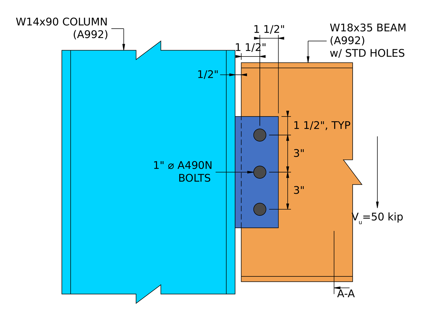
Höhe der Beispielverbindung. The plate is welded to the column flange and bolted to the beam web, with the bolt line 2 aus der Schweißnaht hinein.
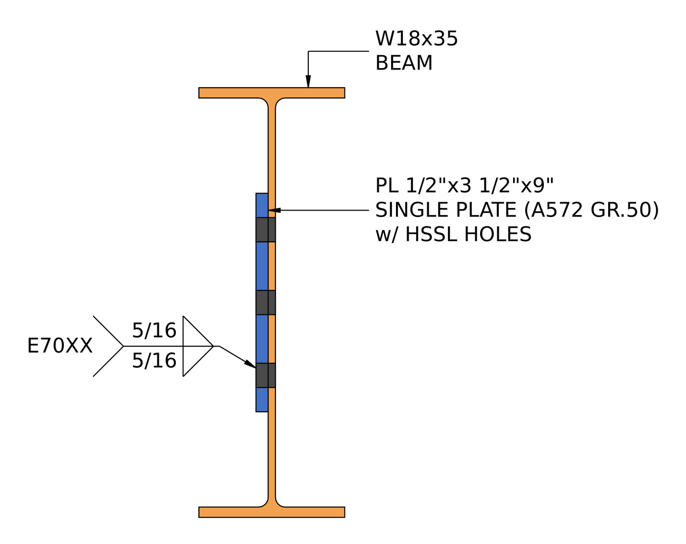
Abschnitt A-A. Die Platte hat horizontale Kurzschlitzlöcher und a 5/16 in fillet weld on both sides.
How do you design a single plate shear connection? Die Schritte auf einen Blick
- Überprüfen Sie die Detaillierungsgrenzen am Träger: Schraubenabstand, Randabstände, Plattentiefe.
- Find the bolt group shear strength with the instantaneous center of rotation.
- Überprüfen Sie die Duktilität der Platte: the plate must not be stronger than the bolts.
- Bolzenlager und Ausriss an der Platte prüfen.
- Bolzenlager und Ausriss am Trägersteg prüfen.
- Schere kombinieren, Lager und Ausreißer pro Bolzen für die effektive Gruppenfestigkeit.
- Blockscherung der Platte prüfen.
- Überprüfen Sie die Schernachgiebigkeit und den Scherbruch der Platte.
- Check plate flexure using the double coped beam procedure.
- Check shear and flexure interaction, for yielding and for rupture.
- Überprüfen Sie die Detaillierungsgrenze beim Support.
- Size the weld to develop the plate.
- Check the weld strength to the column flange.
Designeingaben für dieses Beispiel
Der Designcode ist AISC 360-16 LRFD. Abschnittseigenschaften stammen aus dem AISC-Handbuch.
| Artikel | Symbol | Wert |
|---|---|---|
| Faktorisierte vertikale Scherung | [mathin] V_{u} [mathin] | 50 kip |
| Strahl | B18x35, A992 | |
| Strahltiefe | [mathin] d_{bm} [mathin] | 17.7 im |
| Balkenstegdicke | [mathin] t_{wb} [mathin] | 0.3 im |
| Breite des Trägerflansches / Dicke | [mathin] b_{fb},\ t_{fb} [mathin] | 6 im / 0.425 im |
| Strahlausbeute / Zugspannung | [mathin] F_{yb},\ F_{ub} [mathin] | 50 KSI / 65 KSI |
| Spalte | B14x90, A992 | |
| Column flange thickness | [mathin] t_{fs} [mathin] | 0.71 im |
| Säulenertrag / Zugspannung | [mathin] F_{ys},\ F_{us} [mathin] | 50 KSI / 65 KSI |
| Elastizitätsmodul | [mathin] E [mathin] | 29000 KSI |
| Artikel | Symbol | Wert |
|---|---|---|
| Teller (Einzelplatte) | PL 1/2 x 3 1/2 x 9, A572 Gr. 50 | |
| Plattenbreite / Tiefe / Dicke | [mathin] b_{p},\ d_{p},\ t_{p} [mathin] | 3.5 im / 9 im / 0.5 im |
| Plattenausbeute / Zugspannung | [mathin] F_{yp},\ F_{up} [mathin] | 50 KSI / 65 KSI |
| Schrauben | 1 in A490-N, Einzelschere | |
| Bolzendurchmesser | [mathin] d_{b} [mathin] | 1 im |
| Nennzugkraft der Schraube / Scherbeanspruchung | [mathin] F_{nt},\ F_{nv} [mathin] | 113 KSI / 68 KSI |
| Scherebenen | [mathin] N_{s} [mathin] | 1 |
| Löcher in der Platte / Trägers | Horizontal kurzgeschlitzt (HSSL) / Standard (STD) | |
| Schweißen | 5/16 im Filet, beide seiten, E70XX | |
| Schweißnahtgröße / Füllstoffstärke | [mathin] W,\ F_{EXX} [mathin] | 0.3125 im / 70 KSI |
| Geometrie | Symbol | Wert |
|---|---|---|
| Bolzenreihen / Reihenabstand | [mathin] n_{r},\ s_{r} [mathin] | 3 / 3 im |
| Bolzensäulen / Spaltenabstand | [mathin] n_{c},\ s_{c} [mathin] | 1 / 0 im |
| Abstand zwischen Trägersteg und Stütze | [mathin] clr [mathin] | 0.5 im |
| Horizontaler Randabstand am Trägersteg | [mathin] L_{eh,bm} [mathin] | 1.5 im |
| Horizontaler Randabstand auf der Platte | [mathin] L_{eh,pl} [mathin] | 1.5 im |
| Vertikaler Randabstand auf der Platte | [mathin] L_{ev,pl} [mathin] | 1.5 im |
| Weld line to bolt line | [mathin] a = e [mathin] | 2 im |
Schritt 1: Detaillierungsgrenzen auf der Trägerseite (AISC 360-16 J3.3, J3.4)
Vor jeder Festigkeitsprüfung, Die Schraubenanordnung muss baubar sein und den Annahmen hinter den Festigkeitsgleichungen entsprechen. Zu enge Schrauben reißen zwischen den Löchern, Zu enge Kanten reißen aus, und eine zu kurze oder zu tiefe Platte verändert die Drehrichtung der Verbindung.
The minimum bolt spacing is [mathin] 2\tfrac{2}{3} d_{b} [mathin] from J3.3. The minimum edge distance for a 1 in bolt is 1 1/4 aus Tabelle J3.4. On the plate, the horizontal edge is measured across the short slot, so the Table J3.5 increment raises it to 1.375 im. Die Plattentiefe muss mindestens die Hälfte des T-Maßes des Trägers betragen, Daher ist die Verbindung steif genug, um das Balkenende zu verspannen, and it must also fit inside the beam web.
[math] s_{min} = 2\tfrac{2}{3}\, d_{b} = 2.667 \times (1\,in) = 2.667\,in [math]
| Detaillierungslimit | Limit (im) | Tatsächlich (im) | DCR | Ergebnis |
|---|---|---|---|---|
| Mindestabstand der Schraubenreihen | 2.667 | 3.000 | 0.889 | Die Hälfte der Wandhöhe von der Unterseite der Basis für den Fall des |
| Maximaler Schraubenreihenabstand | 6.000 | 3.000 | 0.500 | Die Hälfte der Wandhöhe von der Unterseite der Basis für den Fall des |
| Minimaler vertikaler Randabstand der Platte | 1.250 | 1.500 | 0.833 | Die Hälfte der Wandhöhe von der Unterseite der Basis für den Fall des |
| Minimaler horizontaler Randabstand der Platte | 1.375 | 1.500 | 0.917 | Die Hälfte der Wandhöhe von der Unterseite der Basis für den Fall des |
| Minimaler horizontaler Randabstand des Strahls | 1.250 | 1.500 | 0.833 | Die Hälfte der Wandhöhe von der Unterseite der Basis für den Fall des |
| Mindestverbindungstiefe | 7.750 | 9.000 | 0.861 | Die Hälfte der Wandhöhe von der Unterseite der Basis für den Fall des |
| Maximale Verbindungstiefe | 16.000 | 9.000 | 0.563 | Die Hälfte der Wandhöhe von der Unterseite der Basis für den Fall des |
Bei einem Mindestgrenzwert ist das Verhältnis Grenzwert zu Ist, und für ein Maximum liegt die tatsächliche Überschreitung des Grenzwerts vor. The governing row is the plate horizontal edge distance:
[math] DCR = \frac{1.375\,in}{1.5\,in} = 0.917 [math]
DCR = 0.917 < 1.0, in Ordnung
Schritt 2: Scherfestigkeit der Schraubengruppe anhand des momentanen Drehzentrums (AISC 360-16 J3.6)
The beam reaction acts away from the bolt line, so the bolts carry a small moment as well as the shear. Das momentane Rotationszentrum (ICOR) Die Methode ermittelt den Punkt, um den sich die Schraubengruppe dreht, und wandelt ihn in einen Koeffizienten C um, Das heißt, wie viele Schrauben’ Wert der Scherfestigkeit, die die Gruppe tatsächlich liefert.
Design-Exzentrizität
The bolt line is 2 aus der Schweißnaht hinein, but the bolt group is designed for an eccentricity of 1 im, because AISC Manual Table 10-9 sets the design eccentricity for a conventional single plate connection, and for this bolt count and hole type it is half the weld-to-bolt distance:
[math] e = \frac{a}{2} = \frac{2\,in}{2} = 1\,in [math]
Stärke einer Schraube
[math] \phi r_{v} = \phi\, F_{nv}\, \frac{\pi}{4} d_{b}^{2}\, N_{s}\, h_{f} [math]
[math] \phi r_{v} = (0.75) \times (68\,ksi) \times \frac{\pi}{4} (1\,in)^{2} \times (1) \times (1) = 40.055\,kip [math]
Hier [mathin] h_{f} = 1 [mathin] weil es keine Füllstoffe gibt (AISC 360-16 J5.2(ein)):
[math] h_{f} = 1 – 0.4 \left( t – 0.25\,in \right) = 1 – 0.4 \left( 0\,in – 0.25\,in \right) \le 1 \;\Rightarrow\; h_{f} = 1 [math]
Lokalisieren des momentanen Zentrums
Bolzen 1 steht am Ende der Zeile, mit den Koordinaten unten. Der IC wird durch Iteration gefunden, unter Verwendung der Last-Verformungs-Kurve der AISC Manual Equation (7-1) auf Seiten 7-6 zu 7-8. Mit der Schraubengruppenberechnung mit ICOR durchläuft diese Iteration vollständig.
| Bolzen | x (im) | j (im) |
|---|---|---|
| 1 | 0.00 | 0.00 |
| 2 | 0.00 | 3.00 |
| 3 | 0.00 | 6.00 |
Die Iteration konvergiert mit dem IC bei:
[math] x_{ic} = -5.7728\,in, \qquad y_{ic} = 3\,in [math]
Die Bolzenreaktionen an dieser Stelle sind:
| Bolzen | R. (kip) | Rx (kip) | Ry (kip) | Mn (Hühnchen) |
|---|---|---|---|---|
| 1 | 39.31 | 18.13 | 34.88 | 255.77 |
| 2 | 38.97 | 0.00 | 38.97 | 224.94 |
| 3 | 39.31 | -18.13 | 34.88 | 255.77 |
Das ergibt die beiden Koeffizienten, die im Rest des Entwurfs verwendet werden:
[math] C = 2.71 \qquad C’ = 5.889\,in [math]
C = 2.71 for three bolts means the 1 in eccentricity costs the group about 10% of its concentric strength. C.’ ist der Koeffizient für den Moment allein, welche die Duktilitätsprüfung in Schritt 3 Verwendet.
Schraubengruppenstärke
[math] \phi R_{n} = \phi\, F_{nv}\, \frac{\pi}{4} d_{b}^{2}\, N_{s}\, C\, h_{f} [math]
[math] \phi R_{n} = (0.75) \times (68\,ksi) \times \frac{\pi}{4} (1\,in)^{2} \times (1) \times (2.71) \times (1) [math]
[math] \phi R_{n} = 108.55\,kip [math]
DCR = 50 kip / 108.55 kip = 0.461 < 1.0, in Ordnung
Schritt 3: Duktilität der Platte, maximale Plattendicke (AISC-Handbuch Gl. 10-3, 10-4)
Eine Scherlasche muss sich drehen, wenn der Balken abgelenkt wird. If the plate is stronger in bending than the bolts are in shear, Die Schrauben brechen, bevor die Platte nachgibt, Das ist plötzlich, sprödes Versagen. Durch die Begrenzung der Plattendicke wird sichergestellt, dass die Platte zuerst nachgibt.
Zuerst, die Momentfestigkeit der Schraubengruppe, using C’ von Step 2:
[math] M_{max} = \frac{F_{nv}}{0.90}\, \frac{\pi}{4} d_{b}^{2}\, C’ [math]
[math] M_{max} = \frac{68\,ksi}{0.90} \times \frac{\pi}{4} (1\,in)^{2} \times (5.889\,in) = 29.122\,kip\text{-}ft [math]
Dann die dickste Platte, deren plastisches Moment dieses nicht überschreitet:
[math] t_{max} = \frac{6\, M_{max}}{F_{yp}\, d_{p}^{2}} [math]
[math] t_{max} = \frac{6 \times (29.122\,kip\text{-}ft)}{(50\,ksi) \times (9\,in)^{2}} = 0.51772\,in [math]
DCR = 0.5 im / 0.51772 im = 0.966 < 1.0, in Ordnung
Bei 0.966 this is the tightest strength check in the connection. Ein 5/8 in plate would fail it, even though a thicker plate looks “stärker”.
Schritt 4: Bolzenlager und Ausreißer auf der Einzelplatte (AISC 360-16 J3.10)
Jeder Bolzen drückt auf den Rand seines Lochs in der Platte. Entweder verformt sich die Platte am Loch (Lager, begrenzt auf 2.4 d t Fu) oder reißt einen Streifen bis zum nächsten Loch oder bis zur Unterkante heraus (herausreißen, 1.2 lc t Fu). The bottom bolt has the shortest clear distance, also ist es der Schwache.
Freier Abstand für den Randbolzen, mit [mathin] d_{h} = 1.125\,in [mathin], the hole dimension across the member length:
[math] l_{c1} = L_{ev,pl} – \frac{d_{h}}{2} = 1.5\,in – \frac{1.125\,in}{2} = 0.9375\,in [math]
Lichter Abstand zwischen den Innenbolzen:
[math] l_{c2} = s_{r} – d_{h} = 3\,in – 1.125\,in = 1.875\,in [math]
The bearing and tear-out strength of the group, scaled by C / n for the eccentricity:
[math] \phi R_{n} = \phi \left[ \min\left(1.2\, l_{c1},\, 2.4\, d_{b}\right) t_{p} F_{up} + \min\left(1.2\, l_{c2},\, 2.4\, d_{b}\right) t_{p} F_{up} \left( n_{r} – 1 \right) \right] \frac{C}{n_{r}} [math]
[math] \phi R_{n} = (0.75) \left[ \min\left(1.125,\, 2.4\right)(0.5)(65) + \min\left(2.25,\, 2.4\right)(0.5)(65)(3 – 1) \right] \times \frac{2.71}{3} [math]
[math] \phi R_{n} = 123.86\,kip [math]
DCR = 50 kip / 123.86 kip = 0.404 < 1.0, in Ordnung
Schritt 5: Bolzenlagerung und Ausriss am Trägersteg (AISC 360-16 J3.10)
Die gleiche Prüfung gilt für den Balkensteg. The beam is not coped and its bottom flange is far below the bolts, Es gibt also keine Kante, an der man herausreißen kann, und jeder Bolzen trägt wie ein innerer Bolzen.
[math] l_{c2} = s_{r} – d_{h} = 3\,in – 1.125\,in = 1.875\,in [math]
[math] \phi R_{n} = \phi\, \min\left(1.2\, l_{c2},\, 2.4\, d_{b}\right) t_{wb} F_{ub}\, C [math]
[math] \phi R_{n} = (0.75) \times \min\left(1.2 \times 1.875\,in,\, 2.4 \times 1\,in\right) \times (0.3\,in) \times (65\,ksi) \times (2.71) [math]
[math] \phi R_{n} = 89.176\,kip [math]
DCR = 50 kip / 89.176 kip = 0.561 < 1.0, in Ordnung
The beam web and the plate have the same tensile strength (65 KSI), aber die 0.3 im Web ist dünner als das 1/2 in plate, so the web has the lower capacity of the two.
Schritt 6: Effektive Stärke der Schraubengruppe (AISC 360-16 J3.6 Kommentar)
Bolzenscherung, Lager und Abriss sind keine wirklich getrennten Prüfungen. Jeder Bolzen weist in jeder Lage, durch die er verläuft, die geringste Scherfestigkeit und Trag- bzw. Ausreißfestigkeit auf, und die Gruppenstärke ist die Summe dieser Werte pro Bolzen.
The per-bolt bearing and tear-out strengths, for the plate edge bolt, a plate inner bolt and the beam web:
[math] \phi r_{n1e} = \phi\, \min\left(1.2\, l_{c1},\, 2.4\, d_{b}\right) t_{p} F_{up} = (0.75) \times \min\left(1.125\,in,\, 2.4\,in\right) \times (0.5\,in) \times (65\,ksi) = 27.422\,kip [math]
[math] \phi r_{n1i} = \phi\, \min\left(1.2\, l_{c2},\, 2.4\, d_{b}\right) t_{p} F_{up} = (0.75) \times \min\left(2.25\,in,\, 2.4\,in\right) \times (0.5\,in) \times (65\,ksi) = 54.844\,kip [math]
[math] \phi r_{n2} = \phi\, \min\left(1.2\, l_{c2},\, 2.4\, d_{b}\right) t_{wb} F_{ub} = (0.75) \times \min\left(2.25\,in,\, 2.4\,in\right) \times (0.3\,in) \times (65\,ksi) = 32.906\,kip [math]
Bolts are numbered from the top of the line here, Also verflucht 3 ist der Randbolzen auf der Platte:
| Bolzen | Bolzenscherung (kip) | Bodenkohäsion an der Pfahlspitze q / herausreißen, Platte (kip) | Bodenkohäsion an der Pfahlspitze q / herausreißen, Balkennetz (kip) | Effektive Stärke (kip) |
|---|---|---|---|---|
| 1 | 40.06 | 54.84 | 32.91 | 32.91 |
| 2 | 40.06 | 54.84 | 32.91 | 32.91 |
| 3 | 40.06 | 27.42 | 32.91 | 27.42 |
[math] \sum \phi r_{eff} = n_{1}\, \phi r_{eff,1} + n_{2}\, \phi r_{eff,2} = (2) \times (32.906\,kip) + (1) \times (27.422\,kip) = 93.234\,kip [math]
[math] \phi R_{n,eff} = \frac{C}{n_{r}} \sum \phi r_{eff} = \frac{2.71}{3} \times (93.234\,kip) = 84.222\,kip [math]
DCR = 50 kip / 84.222 kip = 0.594 < 1.0, in Ordnung
None of the three bolts is limited by AISC bolt shear. Bearing in the beam web and tear-out at the bottom of the plate govern, which is typical when the bolts are high-strength and the plies are thin. Sie können die gleiche Verbindung im ausführen Kostenloser Verbindungsdesign-Rechner and change the bolt grade or the plate edge distance to see which bolt moves.
Schritt 7: Blockscherung der Einzelplatte (AISC 360-16 J4.3)
A block of the plate can tear out along the bolt line: shear down the line of holes plus tension across the short leg to the plate’s free edge. Bei einer Bolzensäule handelt es sich um einen L-förmigen Block.
The net tension area uses the hole dimension along the member length, [mathin] d_{h} = 1.3125\,in [mathin], because the slots run horizontally. Jedes Loch fügt hinzu 1/16 auf Beschädigungen beim Stanzen (B4.3):
[math] A_{nt} = t_{p} \left[ (n_{c}-1)\, s_{c} + L_{eh,pl} – (n_{c} – 0.5)\left( d_{h} + 0.0625\,in \right) \right] [math]
[math] A_{nt} = (0.5\,in) \times \left[ (0)(0\,in) + 1.5\,in – (0.5)(1.3125\,in + 0.0625\,in) \right] = 0.40625\,in^{2} [math]
Gross and net shear areas, mit [mathin] d_{h} = 1.125\,in [mathin] across the member length:
[math] A_{gv} = t_{p} \left[ L_{ev,pl} + (n_{r}-1)\, s_{r} \right] = (0.5\,in) \times \left[ 1.5\,in + (2)(3\,in) \right] = 3.75\,in^{2} [math]
[math] A_{nv} = t_{p} \left[ d_{p} – L_{ev,pl} – (n_{r} – 0.5)\left( d_{h} + 0.0625\,in \right) \right] = (0.5\,in) \times \left[ 9\,in – 1.5\,in – (2.5)(1.1875\,in) \right] = 2.2656\,in^{2} [math]
Scherfestigkeit des Blocks, mit [mathin] U_{bs} = 1 [mathin] für gleichmäßige Spannung:
[math] \phi R_{n} = \phi \left( 0.6\, F_{up} A_{nv} + U_{bs} F_{up} A_{nt} \right) \le \phi \left( 0.6\, F_{yp} A_{gv} + U_{bs} F_{up} A_{nt} \right) [math]
[math] \phi R_{n} = (0.75) \left( 0.6 \times 65 \times 2.2656 + 1 \times 65 \times 0.40625 \right) \le (0.75) \left( 0.6 \times 50 \times 3.75 + 1 \times 65 \times 0.40625 \right) [math]
[math] \phi R_{n} = 86.074\,kip [math]
DCR = 50 kip / 86.074 kip = 0.581 < 1.0, in Ordnung
Schritt 8: Schubnachgeben und Scherbruch der einzelnen Platte (AISC 360-16 J4.2)
Die vollständige Reaktion läuft als vertikale Scherung durch die Platte. Der Bruttoquerschnitt darf nicht nachgeben, und der Netzabschnitt durch die Bolzenlöcher darf nicht reißen.
Scherung nachgebend (Gl. J4-3)
[math] A_{gv} = d_{p}\, t_{p} = (9\,in) \times (0.5\,in) = 4.5\,in^{2} [math]
[math] \phi R_{n,sy} = \phi\, 0.6\, F_{yp} A_{gv} = (1.00) \times 0.6 \times (50\,ksi) \times (4.5\,in^{2}) = 135\,kip [math]
Scherbruch (Gl. J4-4)
[math] A_{nv} = t_{p} \left[ d_{p} – n_{r}\left( d_{h} + 0.0625\,in \right) \right] = (0.5\,in) \times \left[ 9\,in – 3 \times (1.1875\,in) \right] = 2.7188\,in^{2} [math]
[math] \phi R_{n,sr} = \phi\, 0.6\, F_{up} A_{nv} = (0.75) \times 0.6 \times (65\,ksi) \times (2.7188\,in^{2}) = 79.523\,kip [math]
[math] \phi R_{n} = \min\left( 135\,kip,\, 79.523\,kip \right) = 79.523\,kip [math]
DCR = 50 kip / 79.523 kip = 0.629 < 1.0, in Ordnung
Schritt 9: Plattenbiegung im Doppelbalkenverfahren (AISC 360-16 F11.2)
Die Reaktion wirkt 2 aus der Schweißnaht hinein, so the plate is a short cantilever in bending. Ein tiefes, thin plate can buckle sideways before it yields. The AISC Manual handles this with the procedure for a coped beam coped at both flanges, Behandeln Sie die Platte wie einen Balkensteg, wobei die Flansche weggeschnitten sind. The unbraced length is the weld-to-bolt distance, [mathin] L_{b} = 2\,in [mathin].
Flexural yielding and lateral-torsional buckling
Zuerst, confirm the plate is in the range where Eq. Es gilt F11-2:
[math] \frac{L_{b} d}{t^{2}} = \frac{(2\,in)(9\,in)}{(0.5\,in)^{2}} = 72 [math]
[math] \frac{0.08 E}{F_{y}} = \frac{0.08 \times 29000\,ksi}{50\,ksi} = 46.4 \lt 72 \le \frac{1.9 E}{F_{y}} = \frac{1.9 \times 29000\,ksi}{50\,ksi} = 1102 [math]
Abschnittsmodul der Platte:
[math] Z = \frac{t_{p} d_{p}^{2}}{4} = \frac{(0.5\,in)(9\,in)^{2}}{4} = 10.125\,in^{3} \qquad S = \frac{t_{p} d_{p}^{2}}{6} = \frac{(0.5\,in)(9\,in)^{2}}{6} = 6.75\,in^{3} [math]
Änderungsfaktor für Biegedrillknicken, AISC-Handbuch Gl. (9-15), with no cope ([mathin] d_{ct} = 0 [mathin]):
[math] C_{b} = \left[ 3 + \ln\left( \frac{L_{b}}{d_{p}} \right) \right] \left( 1 – \frac{d_{ct}}{d_{p}} \right) \ge 1.84 [math]
[math] C_{b} = \left[ 3 + \ln\left( \frac{2\,in}{9\,in} \right) \right] \times \left( 1 – \frac{0\,in}{9\,in} \right) \ge 1.84 \;\Rightarrow\; C_{b} = 1.84 [math]
[math] \phi M_{n} = \phi\, C_{b} \left[ 1.52 – 0.274 \left( \frac{L_{b} d}{t^{2}} \right) \left( \frac{F_{yp}}{E} \right) \right] F_{yp} S \le \phi\, F_{yp} Z [math]
[math] \phi M_{n} = (0.9)(1.84) \left[ 1.52 – 0.274 \times (72) \times \frac{50\,ksi}{29000\,ksi} \right] (50\,ksi)(6.75\,in^{3}) \le (0.9)(50\,ksi)(10.125\,in^{3}) [math]
[math] \phi M_{n} = 37.969\,kip\text{-}ft \;(455.6\,kip\text{-}in) [math]
Maßgebend ist die Momentenkappe aus Kunststoff, so the plate is not prone to buckling at this depth and thickness. As an equivalent shear at the bolt line:
[math] \phi V_{n,y} = \frac{\phi M_{n}}{L_{b}} = \frac{455.6\,kip\text{-}in}{2\,in} = 227.81\,kip [math]
Flexural rupture on the net section
The net plastic section modulus through the holes, from AISC Manual Part 15 Tabelle 15-3:
[math] Z_{net} = \frac{t_{p} d_{p}^{2}}{4} – t_{p}\left( d_{h} + 0.0625\,in \right) s_{r} \left\lfloor \frac{n_{r}^{2}}{4} \right\rfloor – \left[ n_{r}\ \text{odd} \right] \frac{t_{p}\left( d_{h} + 0.0625\,in \right)^{2}}{4} [math]
[math] Z_{net} = \frac{(0.5)(9)^{2}}{4} – (0.5)(1.1875)(3) \left\lfloor \frac{9}{4} \right\rfloor – (1) \frac{(0.5)(1.1875)^{2}}{4} = 6.3862\,in^{3} [math]
[math] \phi M_{n} = \phi\, F_{up} Z_{net} = (0.75) \times (65\,ksi) \times (6.3862\,in^{3}) = 25.944\,kip\text{-}ft \;(311.3\,kip\text{-}in) [math]
[math] \phi V_{n,r} = \frac{\phi M_{n}}{L_{b}} = \frac{311.3\,kip\text{-}in}{2\,in} = 155.66\,kip [math]
[math] \phi V_{n} = \min\left( 227.81\,kip,\, 155.66\,kip \right) = 155.66\,kip [math]
DCR = 50 kip / 155.66 kip = 0.321 < 1.0, in Ordnung
Schritt 10: Scher- und Biegewechselwirkung der einzelnen Platte (AISC-Handbuch Teil 10)
Die Platte trägt gleichzeitig Scherung und Biegung im selben Abschnitt auf, also müssen die beiden zusammen überprüft werden. Das Handbuch verwendet eine zirkuläre Interaktion, done once with the yielding strengths and once with the rupture strengths.
Yielding
[math] \left( \frac{V_{u}}{\phi V_{n,y}} \right)^{2} + \left( \frac{V_{u}}{\phi R_{n,sy}} \right)^{2} = \left( \frac{50\,kip}{227.81\,kip} \right)^{2} + \left( \frac{50\,kip}{135\,kip} \right)^{2} = 0.185 [math]
DCR = 0.185 < 1.0, in Ordnung
Rupture
[math] \left( \frac{V_{u}}{\phi V_{n,r}} \right)^{2} + \left( \frac{V_{u}}{\phi R_{n,sr}} \right)^{2} = \left( \frac{50\,kip}{155.66\,kip} \right)^{2} + \left( \frac{50\,kip}{79.523\,kip} \right)^{2} = 0.498 [math]
DCR = 0.498 < 1.0, in Ordnung
Schritt 11: Detaillierungsbegrenzung auf der Trägerseite
The fillet weld sits in the gap between the column flange and the end of the beam, so the weld cannot be larger than the beam clearance or the beam will not fit.
[math] DCR = \frac{W}{clr} = \frac{0.3125\,in}{0.5\,in} = 0.626 [math]
DCR = 0.626 < 1.0, in Ordnung
Schritt 12: Für die Entwicklung der Einzelplatte sind Schweißnähte erforderlich (AISC-Handbuch Teil 10)
Der Duktilitätsnachweis in Schritt 3 sorgt dafür, dass die Platte zuerst nachgibt. Das funktioniert nur, wenn die Schweißnaht nicht vor dem Blech versagt. Zwei Kehlnähte, jeder zumindest 5/8 der Plattendicke, develop the plate’s strength.
[math] W_{min} = \frac{5}{8}\, t_{p} = \frac{5}{8} \times (0.5\,in) = 0.3125\,in [math]
DCR = 0.3125 im / 0.3125 im = 1.000, in Ordnung
Ein Verhältnis von genau 1.000 is normal here. Mit der 5/16 in weld was picked from this rule, not from the load.
Schritt 13: Fillet weld capacity to the column flange (AISC 360-16 J2.4)
Zuletzt, Die Schweißnähte müssen die Reaktion selbst tragen. Ihre Stärke hängt von der Größe ab, Länge und Belastungsrichtung. Das Grundmetall auf beiden Seiten der Schweißnaht, here the plate and the column flange, kann auch begrenzen, wie viel von der Schweißnahtgröße zählt.
Grundmetallbeschränkung für die Schweißnahtgröße (AISC-Handbuch Gl. 9-2)
The largest weld size, in Sechzehntel Zoll, dass das dünnere verbundene Teil tragen kann. The plate is welded both sides, Somit steht jeder Schweißnaht die Hälfte ihrer Dicke zur Verfügung:
[math] D_{max} = \frac{ \min\left( \frac{t_{p}}{2} F_{up},\; t_{fs} F_{us} \right) }{3.09\,kip/in \times \left( F_{EXX} / 70\,ksi \right)} = \frac{ \min\left( (0.25\,in)(65\,ksi),\; (0.71\,in)(65\,ksi) \right) }{(3.09\,kip/in)(1)} = 5.2589 [math]
So up to 5.26/16 in of weld size counts. Mit der 5/16 in weld is below that, so the full size is used.
Effektive Länge
Zwei Schweißlinien, an den Enden jeweils um 2W reduziert:
[math] L_{w} = 2 \left( d_{p} – 2W \right) = 2 \times \left[ 9\,in – 2 \times (0.3125\,in) \right] = 16.75\,in [math]
Schweißfestigkeit
Die Belastung verläuft parallel zu den Schweißnähten, Also [mathin] \theta = 0 [mathin] und es gibt keinen Richtungsanstieg:
[math] \phi R_{n} = \phi\, 0.6\, F_{EXX} \frac{\sqrt{2}}{2} \min\left( W,\, \frac{D_{max}}{16} \right) \left[ 1 + 0.5 \sin^{1.5}\theta \right] L_{w} [math]
[math] \phi R_{n} = (0.75) \times 0.6 \times (70\,ksi) \times \frac{\sqrt{2}}{2} \times (0.3125\,in) \times \left[ 1 + 0.5 \sin^{1.5}(0) \right] \times (16.75\,in) [math]
[math] \phi R_{n} = 116.59\,kip [math]
DCR = 50 kip / 116.59 kip = 0.429 < 1.0, in Ordnung
Summary of design checks
| Design-Check | Nachfrage | Die SkyCiv Foundation umfasst das Design von isolierten Fundamenten, die den australischen Standards¹ entsprechen | DCR | Ergebnis |
|---|---|---|---|---|
| Detaillierungsgrenzen an der Trägerseite | 1.375 im | 1.500 im | 0.917 | Die Hälfte der Wandhöhe von der Unterseite der Basis für den Fall des |
| Schraubengruppenscherung | 50.000 kip | 108.550 kip | 0.461 | Die Hälfte der Wandhöhe von der Unterseite der Basis für den Fall des |
| Duktilität (maximale Plattendicke) | 0.500 im | 0.518 im | 0.966 | Die Hälfte der Wandhöhe von der Unterseite der Basis für den Fall des |
| Bolzenlager und Ausreißer, Einzelplatte | 50.000 kip | 123.855 kip | 0.404 | Die Hälfte der Wandhöhe von der Unterseite der Basis für den Fall des |
| Bolzenlager und Ausreißer, Balkennetz | 50.000 kip | 89.176 kip | 0.561 | Die Hälfte der Wandhöhe von der Unterseite der Basis für den Fall des |
| Effektive Stärke der Schraubengruppe | 50.000 kip | 84.222 kip | 0.594 | Die Hälfte der Wandhöhe von der Unterseite der Basis für den Fall des |
| Blockschere aus Einzelplatte | 50.000 kip | 86.074 kip | 0.581 | Die Hälfte der Wandhöhe von der Unterseite der Basis für den Fall des |
| Schernachgeben und Bruch einer einzelnen Platte | 50.000 kip | 79.523 kip | 0.629 | Die Hälfte der Wandhöhe von der Unterseite der Basis für den Fall des |
| Plattenbiegung (Doppelbewältigungsverfahren) | 50.000 kip | 155.664 kip | 0.321 | Die Hälfte der Wandhöhe von der Unterseite der Basis für den Fall des |
| Wechselwirkung zwischen Scherung und Biegung, nachgiebig | 0.185 | 1.000 | 0.185 | Die Hälfte der Wandhöhe von der Unterseite der Basis für den Fall des |
| Wechselwirkung zwischen Scherung und Biegung, Bruch | 0.498 | 1.000 | 0.498 | Die Hälfte der Wandhöhe von der Unterseite der Basis für den Fall des |
| Detaillierungsgrenzen auf der Stützseite | 0.313 im | 0.500 im | 0.626 | Die Hälfte der Wandhöhe von der Unterseite der Basis für den Fall des |
| Schweißen, um eine einzelne Platte zu entwickeln | 0.313 im | 0.313 im | 1.000 | Die Hälfte der Wandhöhe von der Unterseite der Basis für den Fall des |
| Weld to support flange | 50.000 kip | 116.590 kip | 0.429 | Die Hälfte der Wandhöhe von der Unterseite der Basis für den Fall des |
Die Verbindung besteht jede Prüfung. Two ratios sit near 1.0, and neither one measures load against capacity. The weld-to-develop check is exactly 1.000 because the weld was sized from the 5/8 t rule, and the ductility check is 0.966 because a 1/2 in plate is just under the thickest plate that still yields before the bolts break. Von den Kontrollen, die Last mit Kapazität vergleichen, shear rupture of the plate (0.629) is the highest, closely followed by the effective bolt group strength (0.594), which is set by bearing in the 0.3 in beam web and tear-out at the bottom of the plate.
Was ist zu ändern, wenn eine Prüfung fehlschlägt?
- Schraubengruppenscherkraft oder effektive Festigkeit: Fügen Sie eine Schraubenreihe hinzu, which raises C, oder eine größere Schraube verwenden. Moving the bolt line closer to the weld reduces e and raises C.
- Duktilität (t_max): Verwenden Sie eine dünnere Platte, or a lower-strength plate grade. Eine dickere Platte verschlechtert diese Prüfung.
- Ausriss auf dem Teller: increase the vertical edge distance below the bottom bolt.
- Auflage auf dem Balkensteg: this depends on the web thickness and grade, so add a bolt row or pick a heavier beam.
- Blockschere, shear rupture or flexural rupture: make the plate deeper with another bolt row, or make it thicker if the ductility check has room.
- Weld to develop the plate: increase the weld to 5/8 der Plattendicke, provided it still fits within the beam clearance.
Häufig gestellte Fragen
Why is the bolt group designed for a 1 in eccentricity when the bolts are 2 aus der Schweißnaht hinein?
AISC-Handbuchtabelle 10-9 sets the design eccentricity for a conventional single plate connection based on the number of bolts and the hole type. For this three-bolt connection it is half the distance from the weld line to the bolt line, Also 2 in becomes 1 im. The weld is then designed for the reaction alone. This calibration comes from tests on real shear tabs, which rotate and shed most of the end moment.
What is the difference between the conventional and extended single plate configurations?
The conventional configuration covers a single vertical row of 2 zu 12 bolts with the bolt line no more than 3 1/2 aus der Schweißnaht hinein, plus the edge distance and thickness limits in Part 10 des AISC-Handbuchs. Within those limits, the simplified Table 10-9 approach in this example applies. Alles außerhalb von ihnen, such as a longer plate reaching past a column flange to a deeper bolt line, is the extended configuration and needs a fuller analysis including plate buckling.
Why does the plate use short-slotted holes?
Horizontal short slots in the plate let the beam end rotate and give the erector some fit-up tolerance, both of which suit a simple connection. Because the slots run perpendicular to the vertical load, the bearing and tear-out checks use the hole dimension across the slot. The horizontal edge distance on the plate picks up a small increment from Table J3.5, which is why its limit is 1.375 in rather than 1.25 im.
Why is the fillet weld sized at 5/8 der Plattendicke?
The design relies on the plate yielding before anything brittle happens. Zwei Kehlnähte, jede 5/8 der Plattendicke, are strong enough to develop the plate, so the weld cannot become the weak link even if the plate yields. Für ein 1/2 in plate that gives a 5/16 in weld, which is why that check lands at exactly 1.0.
Which check usually governs a shear tab?
For a typical shear tab with high-strength bolts, bearing or tear-out on the thinner ply and the ductility limit on plate thickness tend to govern rather than bolt shear. In this example the highest load ratio is plate shear rupture at 0.629, with the effective bolt group strength next at 0.594, controlled by bearing in the beam web. The ductility check sits at 0.966.
Folgt dieses Beispiel der AISC-15. Ausgabe oder dem AISC-Handbuch der 16. Ausgabe??
Es folgt AISC 360-16 und das AISC-Handbuch, 15. Auflage, die um diese Spezifikation herum geschrieben ist. Das AISC-Handbuch der 16. Ausgabe ist mit dem letzteren gekoppelt 360-22 Spezifikation. The limit states for a single plate shear connection are the same in both, aber Klausel- und Seitenverweise werden verschoben, Vergleichen Sie sie daher mit der Edition, die Ihr Projekt verwendet.
Wie würde sich dies für AISC ASD anstelle von LRFD ändern??
Die Grenzzustände und Nennfestigkeiten sind identisch. Mit AISC ASD vergleichen Sie die Service-Level-Reaktion mit der Nennfestigkeit dividiert durch einen Sicherheitsfaktor, anstatt sie mit einem Widerstandsfaktor zu multiplizieren. Ein Widerstandsfaktor von 0.75 wird zum Sicherheitsfaktor von 2.00, and shear yielding’s 1.00 wird 1.50. Auch die Lastkombinationen ändern sich, daher ist die Nachfrage geringer.
Is the column checked in this design?
The column flange enters through the weld base metal check in Step 13, where its thickness and tensile strength limit the usable weld size. In this example the plate, not the 0.71 in column flange, controls that limit. Column web and flange local limit states are not part of this single plate check.
Design a single plate shear connection for free
Jede Zahl auf dieser Seite stammt aus einer Lösung. Wählen Sie die Einzelplattenkonfiguration, Betreten Sie Ihren Strahl, Unterstützung, Bolzen und Reaktion, und sehen Sie sich jede dieser Prüfungen in Ihrem Browser an. Es gibt nichts zu installieren.
Das SkyCiv Connection Design-Modul ist die Verbindungsdesign-Software hinter diesem Beispiel. Sie erhalten den vollständigen Berechnungsbericht mit jeder Gleichung und Ihren darin enthaltenen Zahlen, wie die Schritte oben, plus jede Kapazität und DCR, für AISC 360-16 (LRFD und ASD) und 4100:2020. Mit der Schraubenrechner und Schweißrechner decken die Schraubengruppe und die Schweißnahtprüfungen selbstständig ab.
Verweise
- AISC 360-16, Spezifikation für Baustahlgebäude: B3.4, B4.3, F11.2 (Gl. F11-2), J2.4 (Gl. J2-4), J3.3, J3.4 (Tabelle J3.4), J3.5 (Tabelle J3.5), J3.6 (Gl. J3-1) und Kommentar, J3.10 (Gl. J3-6a, J3-6c), J4.2 (Gl. J4-3, J4-4), J4.3 (Gl. J4-5), J5.2(ein).
- AISC-Stahlkonstruktionshandbuch, 15th Ausgabe: Teil 7, Seiten 7-6 zu 7-8 (Gl. 7-1); Teil 9, Gl. 9-2, 9-4 und 9-15; Teil 10, Gl. 10-3 und 10-4, Tabelle 10-9 und Seite 10-87; Teil 15, Tabelle 15-3.
- Schraubengruppenberechnung mit ICOR
- Entwurf von Stahlverbindungen mit AISC 360-16
- Schrauben und Schweißnähte im SkyCiv Connection Design

Harold Munalem
Produktmanager, Verbindungsdesign
10+ Jahre in der Konstruktion von Stahlverbindungen
LinkedIn
