
Flush end plate moment connection design to AISC 360 und AISC Design Guide 39 comes down to three things: bolts big enough to carry the flange tension without prying, an end plate thick enough to stay stiff around those bolts, and welds and a column flange that can deliver the force on both sides. The beam moment and axial load are turned into an equivalent moment, and the bolt diameter and plate thickness are sized from a yield line pattern around the tension bolts.
This page works through one real flush end plate moment connection from start to finish: a W21x101 beam bolted to the flange of a W14x211 column through a 1 in end plate with eight 1 in A490-N bolts, carrying a 200 kip-ft moment, ein 125 kip shear and 150 kip of axial tension or compression. It is designed to AISC 360-16 LRFD, the AISC Manual 15th Edition and Design Guide 39. Jede Gleichung wird mit ihren Zahlen ausgeschrieben, in the same order as the AISC calc sheet the SkyCiv-Verbindungsdesign module produces for it.
What is a flush end plate moment connection?
An end plate moment connection is a plate welded to the end of a beam in the shop and bolted to the column on site. In a flush end plate, the plate stops at the beam flanges, so every bolt sits between the flanges. In an extended end plate, the plate projects past the tension flange and carries a bolt row outside it. The flush version is easier to fit into a floor and has nothing sticking up past the beam, but its bolts have a shorter lever arm, so it suits moderate moments.
es ist ein Moment Verbindung: the welds and bolts are designed so the joint transfers the full beam moment into the column, rather than letting the beam end rotate. The same plate made shallower and welded to the web only is an end plate shear connection, and both are covered by the Endplattenverbindungsrechner. Mit der Moment Verbindungen page compares it with the flange plate moment connection and other details.
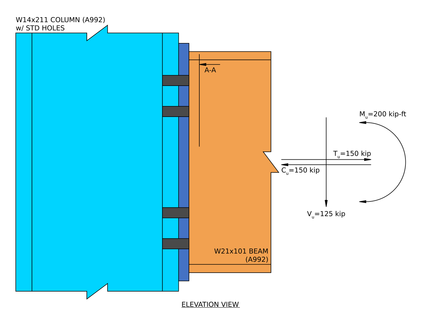
Elevation. The end plate is welded to the end of the W21x101 and bolted to the W14x211 column flange with two bolt rows near each beam flange.
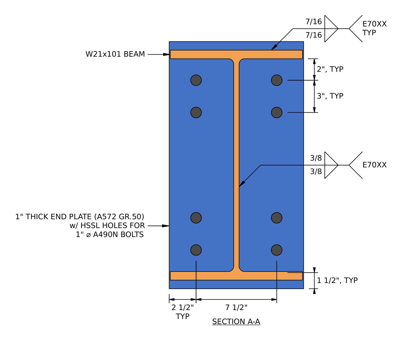
Abschnitt A-A. Four rows of two bolts at a 7 1/2 im Messgerät, 2 in from the inside face of each flange and 3 auseinander. The plate extends 1 1/2 in past each flange so the flange welds fit.
Flush end plate moment connection design: the steps at a glance
The design follows AISC Design Guide 39: size the bolts and the plate for the moment first, then check the welds, the bolts in shear and the column.
- Check the detailing limits for the welds, bolts and plate.
- Find the equivalent moment and the required bolt diameter.
- Find the yield line parameter and the required end plate thickness.
- Check the fillet welds at the beam flange.
- Check the beam flange base metal at the weld.
- Check the fillet welds at the beam web for tension.
- Check the beam web base metal at the weld.
- Check the fillet welds at the beam web for shear.
- Check the bolts in shear.
- Bolzenlager und Ausriss an der Endplatte prüfen.
- Bolzenlager und Ausriss am Säulenflansch prüfen.
- Check column flange bending at the tension bolts.
- Check the column under the compression flange force.
Designeingaben für dieses Beispiel
Der Designcode ist AISC 360-16 LRFD, with the end plate procedure from AISC Design Guide 39. Abschnittseigenschaften stammen aus dem AISC-Handbuch.
| Belastung | Symbol | Wert |
|---|---|---|
| Faktorisierte vertikale Scherung | [mathin] V_{u} [mathin] | 125 kip |
| Factored axial tension | [mathin] T_{u} [mathin] | 150 kip |
| Factored axial compression | [mathin] C_{u} [mathin] | 150 kip |
| Factored strong-axis moment | [mathin] M_{ux} [mathin] | 200 kip-ft |
| Member property | Symbol | Strahl | Spalte |
|---|---|---|---|
| Sektion | W21x101, A992 | W14x211, A992 | |
| Tiefe | [mathin] d_{bm},\ d_{sup} [mathin] | 21.4 im | 15.7 im |
| Bahndicke | [mathin] t_{wb},\ t_{ws} [mathin] | 0.5 im | 0.98 im |
| Flange width | [mathin] b_{fb},\ b_{fs} [mathin] | 12.3 im | 15.8 im |
| Flange thickness | [mathin] t_{fb},\ t_{fs} [mathin] | 0.8 im | 1.56 im |
| Bereich | [mathin] A [mathin] | 29.8 in² | 62 in² |
| Ertrag / Zugspannung | [mathin] F_{y},\ F_{u} [mathin] | 50 KSI / 65 KSI | 50 KSI / 65 KSI |
| Elastizitätsmodul | [mathin] E [mathin] | 29000 KSI | 29000 KSI |
| Endplatte, Schrauben und Schweißnähte | Symbol | Wert |
|---|---|---|
| Breite der Endplatte / Tiefe / Dicke | [mathin] b_{p},\ d_{p},\ t_{p} [mathin] | 12.5 im / 23 im / 1 im, A572 Gr. 50 |
| Plattenausbeute / Zugspannung | [mathin] F_{yp},\ F_{up} [mathin] | 50 KSI / 65 KSI |
| Schrauben | [mathin] d_{b} [mathin] | 1 in A490-N, one shear plane |
| Nennzugkraft der Schraube / Scherbeanspruchung | [mathin] F_{nt},\ F_{nv} [mathin] | 113 KSI / 68 KSI |
| Löcher in der Endplatte / Säulenflansch | Horizontal kurzgeschlitzt (HSSL) / Standard (STD) | |
| Bolzenreihen / Reihenabstand | [mathin] n_{r},\ s_{r} [mathin] | 4 / 3 im |
| Bolzensäulen / Messgerät | [mathin] n_{c},\ g [mathin] | 2 / 7.5 im |
| Bolt flange offset (inside face of flange to first row) | [mathin] p_{f} [mathin] | 2 im |
| Fillet weld at beam flanges | [mathin] W_{1} [mathin] | 0.4375 im (7/16 im), E70XX |
| Fillet weld at beam web | [mathin] W_{2} [mathin] | 0.375 im (3/8 im), E70XX |
Schritt 1: Detailing limits (AISC 360-16 J2.2b, J3.3, J3.4, J3.5)
Vor jeder Festigkeitsprüfung, the connection has to be buildable and match the assumptions behind the Design Guide 39 Gleichungen. The welds must be at least the minimum size for the parts they join, the bolts must be far enough apart and far enough from the edges, and the plate must be deep enough to take the flange welds.
The minimum fillet weld sizes come from Table J2.4: 5/16 in for the flanges, where the thinner part joined is the 0.8 in flange, und 3/16 in for the 0.5 im Web. The minimum bolt spacing is [mathin] 2\tfrac{2}{3} d_{b} [mathin] from J3.3, and the edge distances come from Table J3.4. Die Endplatte hat horizontale kurze Schlitze, so Table J3.5 adds 1/8 in to its horizontal edge distance, geben 1.375 im. The maximum gage on the end plate is the beam flange width, 12.3 im, so the bolts stay inside the flange.
| Detaillierungslimit | Limit (im) | Tatsächlich (im) | DCR | Ergebnis |
|---|---|---|---|---|
| Minimum weld size at flanges | 0.313 | 0.438 | 0.714 | Die Hälfte der Wandhöhe von der Unterseite der Basis für den Fall des |
| Minimum weld size at web | 0.188 | 0.375 | 0.500 | Die Hälfte der Wandhöhe von der Unterseite der Basis für den Fall des |
| Minimum plate height to allow welding | 22.525 | 23.000 | 0.979 | Die Hälfte der Wandhöhe von der Unterseite der Basis für den Fall des |
| Mindestabstand der Schraubenreihen | 2.667 | 3.000 | 0.889 | Die Hälfte der Wandhöhe von der Unterseite der Basis für den Fall des |
| Maximaler Schraubenreihenabstand | 6.000 | 3.000 | 0.500 | Die Hälfte der Wandhöhe von der Unterseite der Basis für den Fall des |
| End plate minimum vertical edge distance | 1.250 | 1.500 | 0.833 | Die Hälfte der Wandhöhe von der Unterseite der Basis für den Fall des |
| End plate minimum horizontal edge distance | 1.375 | 2.500 | 0.550 | Die Hälfte der Wandhöhe von der Unterseite der Basis für den Fall des |
| Unterstützen Sie den minimalen horizontalen Randabstand | 1.250 | 4.150 | 0.301 | Die Hälfte der Wandhöhe von der Unterseite der Basis für den Fall des |
| Mindestbolzenmaß an der Stütze | 5.375 | 7.500 | 0.717 | Die Hälfte der Wandhöhe von der Unterseite der Basis für den Fall des |
| Mindestbolzenmaß an der Endplatte | 3.250 | 7.500 | 0.433 | Die Hälfte der Wandhöhe von der Unterseite der Basis für den Fall des |
| Maximum bolt gage at end plate | 12.300 | 7.500 | 0.610 | Die Hälfte der Wandhöhe von der Unterseite der Basis für den Fall des |
| Minimum bolt flange offset | 1.438 | 2.000 | 0.719 | Die Hälfte der Wandhöhe von der Unterseite der Basis für den Fall des |
Bei einem Mindestgrenzwert ist das Verhältnis Grenzwert zu Ist, und für ein Maximum liegt die tatsächliche Überschreitung des Grenzwerts vor. The governing row is the plate height:
[math] DCR = \frac{d}{c} = \frac{(22.525)}{(23)} = 0.97935 [math]
DCR = 0.979 < 1.0, in Ordnung
The minimum plate height is 1.125 in more than the 21.4 in beam depth, oder 0.5625 in past each flange: room for the 7/16 in flange weld plus 1/8 im. Mit der 23 in plate gives 0.8 in each side, so it passes with little to spare. That is normal for a flush plate, which is meant to stop just past the flanges.
Schritt 2: Required bolt diameter (AISC-Designhandbuch 39, Gl. 3-30 and 5-3a)
The bolts near the tension flange carry the moment as tension. Design-Leitfaden 39 sizes them so they reach their tensile strength without any prying force, which is only possible if the end plate is then made thick enough to stay stiff (Schritt 3).
Equivalent moment with axial tension
Axial tension pulls on the tension bolts as well. The guide adds it to the moment as half the tension acting over the distance between the flange centroids:
[math] M_{u,eq} = M_{ux} + \frac{T_{u}}{2} \left( d_{bm} – t_{fb} \right) [math]
[math] M_{u,eq} = (200\,kip\text{-}ft) + \frac{(150\,kip)}{2} \times \left( (21.4\,in) – (0.8\,in) \right) = 328.75\,kip\text{-}ft [math]
Bolt lever arms
The tension bolts rotate about the centre of the compression flange. [mathin] h_{1} = 18.2\,in [mathin] is the distance from there to the farther tension bolt row, the one 2 in inside the tension flange, und [mathin] h_{2} = 15.2\,in [mathin] is the distance to the next row, 3 in further in. Es gibt [mathin] n_{c} = 2 [mathin] bolts in each row:
[math] \sum_{i} n_{i} h_{i} = n_{c} \left( h_{1} + h_{2} \right) = 66.8\,in [math]
Required bolt diameter
Wo [mathin] \phi = 0.75 [mathin] is the resistance factor for bolt tension and [mathin] F_{nt} = 113\,ksi [mathin] is the nominal tensile stress of an A490 bolt:
[math] d_{b,reqd} = \sqrt{\frac{4\, M_{u,eq}}{\pi\, \phi\, F_{nt} \sum_{i} n_{i} h_{i}}} [math]
[math] d_{b,reqd} = \sqrt{\frac{4 \times (328.75\,kip\text{-}ft)}{\pi \times (0.75) \times (113\,ksi) \times (66.8\,in)}} [math]
[math] d_{b,reqd} = 0.94193\,in [math]
[math] DCR = \frac{d_{b,reqd}}{d_{b}} = \frac{(0.94193\,in)}{(1\,in)} = 0.94193 [math]
DCR = 0.942 < 1.0, in Ordnung
The axial tension adds 128.75 kip-ft to the 200 kip-ft moment, so it drives a large share of the bolt size.
Schritt 3: Required end plate thickness (AISC-Designhandbuch 39, Tabelle 5-3 und Gl. 5-5ein)
The end plate bends around the tension bolts. Design-Leitfaden 39 finds its strength from a yield line pattern: the set of hinge lines that form in the plate when it fails. The plate is then made thick enough that it stays elastic, so the bolts see no prying.
Yield line parameter
The yield line pitch s locates the hinge lines below the bolts:
[math] s = \frac{\sqrt{b_{p}\, g}}{2} = \frac{\sqrt{(12.5\,in)(7.5\,in)}}{2} = 4.8412\,in [math]
For a four-bolt flush unstiffened end plate, Tabelle 5-3 gives:
[math] Y_{p} = \frac{b_{p}}{2} \left( \frac{h_{1}}{p_{f}} + \frac{h_{2}}{s} \right) + \frac{2}{g} \left( h_{1} \left( p_{f} + \frac{3 s_{r}}{4} \right) + h_{2} \left( s + \frac{s_{r}}{4} \right) \right) + \frac{g}{2} [math]
Mit [mathin] b_{p} = 12.5\,in [mathin], [mathin] g = 7.5\,in [mathin], [mathin] h_{1} = 18.2\,in [mathin], [mathin] h_{2} = 15.2\,in [mathin], [mathin] p_{f} = 2\,in [mathin], [mathin] s = 4.8412\,in [mathin] und [mathin] s_{r} = 3\,in [mathin]:
[math] Y_{p} = 123.54\,in [math]
Required plate thickness
Wo [mathin] \gamma_{r} = 0.8 [mathin] is the Design Guide 39 reduction factor for flush end plates, which keeps the connection fully restrained, [mathin] \phi = 0.9 [mathin] is the resistance factor for flexure and [mathin] F_{yp} = 50\,ksi [mathin]:
[math] t_{p,reqd} = \sqrt{\frac{1.10\, M_{u,eq}}{\gamma_{r}\, \phi\, F_{yp}\, Y_{p}}} [math]
[math] t_{p,reqd} = \sqrt{\frac{1.10 \times (328.75\,kip\text{-}ft)}{(0.8) \times (0.9) \times (50\,ksi) \times (123.54\,in)}} [math]
[math] t_{p,reqd} = 0.9878\,in [math]
[math] DCR = \frac{t_{p,reqd}}{t_{p}} = \frac{(0.9878\,in)}{(1\,in)} = 0.9878 [math]
DCR = 0.988 < 1.0, in Ordnung
Mit der 1.10 factor keeps the plate’s yield line strength 10% above the demand, so the plate stays stiff and the no-prying assumption in Step 2 holds.
Schritt 4: Fillet weld at the beam flange (AISC-Designhandbuch 39 Gl. 3-38ein, AISC 360-16 J2.4)
The flange welds carry the flange force from the beam into the end plate. They are fillet welds on both faces of the flange, loaded perpendicular to their length.
Effektive Schweißnahtlänge
The outside weld runs the full width of the flange. The inside weld stops short of the web on each side, by the distance [mathin] k_{1} = 1.4375\,in [mathin] from the web centreline to the toe of the flange fillet:
[math] L_{w} = 2 \left( \min\left( b_{fb},\, b_{p} \right) \right) – 2 k_{1} [math]
[math] L_{w} = 2 \left( \min\left( (12.3\,in),\, (12.5\,in) \right) \right) – 2 (1.4375\,in) = 21.725\,in [math]
Flange force
The flange force is the moment divided by the distance between flange centroids, plus half the larger axial load. Design-Leitfaden 39 also sets a floor of 60% of the flange’s yield strength, so the welds are never the weak link even when the moment is small:
[math] P_{fl} = \max\left( \frac{M_{ux}}{d_{bm} – t_{fb}} + \frac{\max\left( T_{u},\, C_{u} \right)}{2},\, 0.6\, F_{yb}\, b_{fb}\, t_{fb} \right) [math]
[math] P_{fl} = \max\left( \frac{(200\,kip\text{-}ft)}{(21.4\,in) – (0.8\,in)} + \frac{\max\left( (150\,kip),\, (150\,kip) \right)}{2},\, 0.6\,(50\,ksi)\,(12.3\,in)\,(0.8\,in) \right) [math]
[math] P_{fl} = 295.2\,kip [math]
The moment and axial load give 191.5 kip, also die 60% floor of 295.2 kip governs.
Schweißfestigkeit
Wo [mathin] F_{EXX} = 70\,ksi [mathin], [mathin] W_{1} = 0.4375\,in [mathin], [mathin] \phi = 0.75 [mathin], and the factor 1.5 is the J2.4 directional strength increase for a weld loaded perpendicular to its axis:
[math] \phi R_{n} = \phi\, 0.6\, F_{EXX} \left( \frac{\sqrt{2}}{2} W_{1} \right) L_{w}\, 1.5 [math]
[math] \phi R_{n} = (0.75)\, 0.6\, (70\,ksi) \left( \frac{\sqrt{2}}{2} (0.4375\,in) \right) (21.725\,in)\, 1.5 [math]
[math] \phi R_{n} = 317.56\,kip [math]
[math] DCR = \frac{P_{fl}}{\phi R_{n}} = \frac{(295.2\,kip)}{(317.56\,kip)} = 0.9296 [math]
DCR = 0.930 < 1.0, in Ordnung
Schritt 5: Beam flange base metal at the weld (AISC 360-16 J4.1)
The flange metal next to the weld has to carry the same force. It is checked as a tension element, yielding and rupture, over the length of one weld line, because the welds on both faces of the flange load the same piece of flange.
Mit [mathin] 0.5 L_{w} = 10.863\,in [mathin] for one weld line:
[math] \phi R_{n,ty} = \phi\, F_{yb}\, t_{fb}\, 0.5 L_{w} = (0.9) \times (50\,ksi) \times (0.8\,in) \times (10.863\,in) = 391.05\,kip [math]
[math] \phi R_{n,tr} = \phi\, F_{ub}\, t_{fb}\, 0.5 L_{w} = (0.75) \times (65\,ksi) \times (0.8\,in) \times (10.863\,in) = 423.64\,kip [math]
[math] \phi R_{n} = \min\left( \phi R_{n,ty},\, \phi R_{n,tr} \right) = \min\left( (391.05\,kip),\, (423.64\,kip) \right) = 391.05\,kip [math]
[math] DCR = \frac{P_{fl}}{\phi R_{n}} = \frac{(295.2\,kip)}{(391.05\,kip)} = 0.75489 [math]
DCR = 0.755 < 1.0, in Ordnung
Schritt 6: Fillet weld at the beam web in tension (AISC-Designhandbuch 39 Feige. 3-17, Gl. 3-39 to 3-41a)
The tension bolts sit right next to the beam web, so part of their force goes into the web rather than the flange. The web welds near the tension bolts have to carry that force into the end plate.
Effective weld length in tension
Only the web weld near the tension bolts counts: from the end of the flange fillet down past the last tension bolt row plus 6 im, but no further than mid-depth. Mit [mathin] k_{det} = 2.0625\,in [mathin] und [mathin] n_{rt} = 2 [mathin] bolt rows in tension:
[math] L_{wt} = 2 \left( \min\left( p_{f} – \left( k_{det} – t_{fb} \right) + s_{r} \left( n_{rt} – 1 \right) + 6\,in,\, 0.5\, d_{bm} – k_{det} \right) \right) [math]
[math] L_{wt} = 2 \left( \min\left( (2\,in) – \left( (2.0625\,in) – (0.8\,in) \right) + (3\,in)\left( (2) – 1 \right) + 6\,(1\,in),\, 0.5\,(21.4\,in) – (2.0625\,in) \right) \right) [math]
[math] L_{wt} = 17.275\,in [math]
The mid-depth limit governs here.
Force on the web weld
Alle [mathin] n_{t} = 4 [mathin] tension bolts are next to the web, Also [mathin] n_{trib} = 4 [mathin] and the web takes the full tension flange force. Again there is a floor, Hier 60% of the yield strength of the web over the weld length:
[math] P_{w} = \max\left( \frac{n_{trib}}{n_{t}} \left( \frac{M_{ux}}{d_{bm} – t_{fb}} + \frac{T_{u}}{2} \right),\, 0.6\, F_{yb} \left( 0.5 L_{wt} \right) t_{wb} \right) [math]
[math] P_{w} = \max\left( \frac{(4)}{(4)} \left( \frac{(200\,kip\text{-}ft)}{(21.4\,in) – (0.8\,in)} + \frac{(150\,kip)}{2} \right),\, 0.6\,(50\,ksi)\,(0.5\,(17.275\,in))\,(0.5\,in) \right) [math]
[math] P_{w} = 191.5\,kip [math]
Schweißfestigkeit
[math] \phi R_{n} = \phi\, 0.6\, F_{EXX} \left( \frac{\sqrt{2}}{2} W_{2} \right) L_{wt}\, 1.5 [math]
[math] \phi R_{n} = (0.75)\, 0.6\, (70\,ksi) \left( \frac{\sqrt{2}}{2} (0.375\,in) \right) (17.275\,in)\, 1.5 = 216.44\,kip [math]
[math] DCR = \frac{P_{w}}{\phi R_{n}} = \frac{(191.5\,kip)}{(216.44\,kip)} = 0.8848 [math]
DCR = 0.885 < 1.0, in Ordnung
Schritt 7: Beam web base metal at the weld (AISC 360-16 J4.1)
The web next to the tension weld has to carry the same 191.5 kip without yielding or rupturing. As with the flange, the length is one weld line, [mathin] 0.5 L_{w} = 8.6375\,in [mathin].
[math] \phi R_{n,ty} = \phi\, F_{yb}\, t_{wb}\, 0.5 L_{w} = (0.9) \times (50\,ksi) \times (0.5\,in) \times (8.6375\,in) = 194.34\,kip [math]
[math] \phi R_{n,tr} = \phi\, F_{ub}\, t_{wb}\, 0.5 L_{w} = (0.75) \times (65\,ksi) \times (0.5\,in) \times (8.6375\,in) = 210.54\,kip [math]
[math] \phi R_{n} = \min\left( (194.34\,kip),\, (210.54\,kip) \right) = 194.34\,kip [math]
[math] DCR = \frac{P_{w}}{\phi R_{n}} = \frac{(191.5\,kip)}{(194.34\,kip)} = 0.98539 [math]
DCR = 0.985 < 1.0, in Ordnung
Mit der 1/2 in web is what limits this check. A bigger web weld would not help, because the web itself yields first.
Schritt 8: Fillet weld at the beam web in shear (AISC 360-16 J2.4, AISC-Handbuch Gl. 9-2)
The beam shear goes into the end plate through the web welds. Design-Leitfaden 39 assigns it to the web weld outside the tension zone of Step 6.
Effective weld length in shear
[math] L_{wv} = 2 \left( \min\left( d_{bm} – 2 k_{det} – 0.5 L_{wt},\, 0.5\, d_{bm} – k_{det} \right) \right) [math]
[math] L_{wv} = 2 \left( \min\left( (21.4\,in) – 2\,(2.0625\,in) – 0.5\,(17.275\,in),\, 0.5\,(21.4\,in) – (2.0625\,in) \right) \right) = 17.275\,in [math]
Base metal limit on the weld size
A fillet weld can be no stronger than the metal it is welded to. Manuelle Gl. 9-2 gives the largest weld size, in Sechzehntel Zoll, that the base metal can support. The web has welds on both faces, so each weld gets half the web thickness:
[math] D_{max} = \frac{t_{p}\, F_{up} \le \frac{t_{wb}}{2}\, F_{ub}}{3.09\,kip/in \times F_{EXX}/F_{E70XX}} [math]
[math] D_{max} = \frac{(1\,in) \times (65\,ksi) \le (0.25\,in) \times (65\,ksi)}{(3.09\,kip/in) \times (1)} = 5.2589 [math]
The effective weld size is therefore [mathin] 5.2589/16 = 0.3287\,in [mathin], less than the 3/8 in specified.
Schweißfestigkeit
The shear runs along the weld, so there is no directional increase:
[math] \phi R_{n} = \phi\, 0.6\, F_{EXX} \frac{\sqrt{2}}{2} \left( W_{2} \le \frac{D_{max}}{16} \right) L_{wv} [math]
[math] \phi R_{n} = (0.75) \times 0.6 \times (70\,ksi) \times \frac{\sqrt{2}}{2} \times \left( (0.375\,in) \le \frac{(5.2589)}{(16)} \right) \times (17.275\,in) [math]
[math] \phi R_{n} = 126.47\,kip [math]
[math] DCR = \frac{V_{u}}{\phi R_{n}} = \frac{(125\,kip)}{(126.47\,kip)} = 0.98837 [math]
DCR = 0.988 < 1.0, in Ordnung
This is the governing check of the connection, just ahead of the end plate thickness. The capacity is set by the beam web, so a larger weld adds nothing.
Schritt 9: Bolzenscherung (AISC 360-16 J3.6)
The bolts also carry the beam shear across the joint between the end plate and the column flange. They are bearing-type A490-N bolts, with threads included in the shear plane, so each has a nominal shear stress of [mathin] F_{nv} = 68\,ksi [mathin].
Wo [mathin] \phi = 0.75 [mathin], [mathin] N_{s} = 1 [mathin] shear plane, und [mathin] n_{v} = 12 [mathin] is the number of bolts the report counts as resisting shear:
[math] \phi R_{n} = \phi\, F_{nv} \frac{\pi}{4} \left( d_{b} \right)^{2} N_{s}\, h_{f}\, n_{v} [math]
[math] \phi R_{n} = (0.75) \times (68\,ksi) \times \frac{\pi}{4} \times \left( (1\,in) \right)^{2} \times (1) \times (1) \times (12) [math]
[math] \phi R_{n} = 480.66\,kip [math]
DCR = 125 kip / 480.66 kip = 0.260 < 1.0, in Ordnung
Design-Leitfaden 39 normally assigns the shear to the compression side bolts, because the tension bolts are already working in tension. Bolt shear has a lot of reserve here either way.
Schritt 10: Bolzenlager und Ausreißer an der Endplatte (AISC 360-16 J3.10)
Each bolt pushes on the edge of its hole in the end plate. Entweder verformt sich die Platte am Loch (Lager) or tears a strip out toward the next hole (herausreißen). The beam shear pushes the end plate down, so each bolt bears on the top edge of its hole.
The slots run horizontally, so the vertical load meets the 1.125 in slot width:
[math] l_{c2} = s_{r} – d_{h} = (3\,in) – (1.125\,in) = 1.875\,in [math]
Mit [mathin] t_{p} = 1\,in [mathin], [mathin] F_{up} = 65\,ksi [mathin], [mathin] n_{v} = 12 [mathin] und [mathin] \phi = 0.75 [mathin]:
[math] \phi R_{n,tearout} = \phi\, \min\left( 1.2\, l_{c2},\, 2.4\, d_{b} \right) t_{p}\, F_{up}\, n_{v} [math]
[math] \phi R_{n,tearout} = (0.75) \times \min\left( 1.2 \times (1.875\,in),\, 2.4 \times (1\,in) \right) \times (1\,in) \times (65\,ksi) \times (12) [math]
[math] \phi R_{n,tearout} = 1316.3\,kip [math]
DCR = 125 kip / 1316.3 kip = 0.095 < 1.0, in Ordnung
Schritt 11: Bolzenlager und Ausreißer am Säulenflansch (AISC 360-16 J3.10)
Die gleiche Prüfung gilt für den Stützenflansch, which has standard holes and is 1.56 in dick:
[math] \phi R_{n,tearout} = \phi\, \min\left( 1.2\, l_{c2},\, 2.4\, d_{b} \right) t_{fs}\, F_{us}\, n_{v} [math]
[math] \phi R_{n,tearout} = (0.75) \times \min\left( 1.2 \times (1.875\,in),\, 2.4 \times (1\,in) \right) \times (1.56\,in) \times (65\,ksi) \times (12) [math]
[math] \phi R_{n,tearout} = 2053.3\,kip [math]
DCR = 125 kip / 2053.3 kip = 0.061 < 1.0, in Ordnung
Schritt 12: Column flange bending at the tension bolts (AISC-Designhandbuch 39, Table A-2 and Eq. 3-43)
The tension bolts pull on the column flange as well as on the end plate, so the column flange can bend into the same kind of yield line pattern. If it is too thin, the column needs stiffeners or backing plates at the tension bolts.
The yield line pitch for the column flange uses its width:
[math] s = \frac{\sqrt{b_{fs}\, g}}{2} = \frac{\sqrt{(15.8\,in)(7.5\,in)}}{2} = 5.4429\,in [math]
For a four-bolt pattern on an unstiffened column that continues above and below the connection, Table A-2 gives, mit [mathin] c = 3\,in [mathin] (the bolt row spacing, for a flush plate):
[math] Y_{c} = \frac{b_{fs}}{2} \left( \frac{h_{1}}{s} + \frac{h_{2}}{s} \right) + \frac{2}{g} \left( h_{1} \left( s + \frac{3c}{4} \right) + h_{2} \left( s + \frac{c}{4} \right) \right) + \frac{g}{2} = 114.67\,in [math]
The flexural strength of the column flange is:
[math] M_{cf} = \phi\, F_{ys}\, t_{fs}^{2}\, Y_{c} = (0.9)\,(50\,ksi)\,(1.56\,in)^{2}\,(114.67\,in) = 1046.4\,kip\text{-}ft [math]
It is compared with the same 1.10 times the equivalent moment used for the end plate:
[math] DCR = \frac{1.1\, M_{u,eq}}{M_{cf}} = \frac{(361.62\,kip\text{-}ft)}{(1046.4\,kip\text{-}ft)} = 0.34558 [math]
DCR = 0.346 < 1.0, in Ordnung
The W14x211 flange is 1.56 in dick, and strength goes up with the square of the thickness, so no stiffeners are needed.
Schritt 13: Column under the compression flange force (AISC 360-16 J10, AISC-Designhandbuch 39)
The compression flange of the beam pushes the end plate into the column flange. That concentrated force has to be carried by the column flange and web without local failure, and the column web panel has to carry it as shear.
Compression flange force
[math] P_{fc} = \frac{M_{ux}}{d_{bm} – t_{fb}} + \frac{C_{u}}{2} = \frac{(200\,kip\text{-}ft)}{(21.4\,in) – (0.8\,in)} + \frac{(150\,kip)}{2} = 191.5\,kip [math]
Flange local bending (Gl. J10-1)
[math] \phi R_{n,flb} = \phi\, 6.25\, F_{ys} \left( t_{fs} \right)^{2} = (0.9) \times 6.25 \times (50\,ksi) \times \left( (1.56\,in) \right)^{2} = 684.45\,kip [math]
Web compression buckling (Gl. J10-8)
With the column T dimension, [mathin] T_{sup} = 10\,in [mathin], as the web depth and [mathin] Q_{f} = 1 [mathin]:
[math] \phi R_{n,wcb} = \phi \left( \frac{24\, t_{ws}^{3} \sqrt{E\, F_{ys}}}{T_{sup}} \right) Q_{f} = (0.9) \times \left( \frac{24 \times (0.98\,in)^{3} \times \sqrt{(29000\,ksi) \times (50\,ksi)}}{(10\,in)} \right) \times (1) = 2448\,kip [math]
Bearing length (Design-Leitfaden 39 Gl. 3-47)
The flange force spreads through the flange welds and the end plate before it reaches the column. Below the flange, the spread stops at the edge of the plate. That distance is [mathin] d_{pe} = 0.3625\,in [mathin]: bleibt die 0.8 in the plate extends past the flange, less the 7/16 in weld.
[math] l_{b} = t_{fb} + 2 W_{1} + t_{p} + \min\left( d_{pe},\, t_{p} \right) [math]
[math] l_{b} = (0.8\,in) + 2\,(0.4375\,in) + (1\,in) + \min\left( (0.3625\,in),\, (1\,in) \right) = 3.0375\,in [math]
Web local crippling (Gl. J10-4)
[math] \phi R_{n,wlc} = \phi\, 0.8 \left( t_{ws} \right)^{2} \left[ 1 + 3 \left( \frac{l_{b}}{d_{sup}} \right) \left( \frac{t_{ws}}{t_{fs}} \right)^{1.5} \right] \sqrt{\frac{E\, F_{ys}\, t_{fs}}{t_{ws}}}\, Q_{f} [math]
[math] \phi R_{n,wlc} = (0.75) \times 0.8 \times \left( (0.98\,in) \right)^{2} \times \left[ 1 + 3 \times \left( \frac{(3.0375\,in)}{(15.7\,in)} \right) \times \left( \frac{(0.98\,in)}{(1.56\,in)} \right)^{1.5} \right] \times \sqrt{\frac{(29000\,ksi) \times (50\,ksi) \times (1.56\,in)}{(0.98\,in)}} \times (1) = 1128.5\,kip [math]
Web local yielding (Design-Leitfaden 39 Gl. 3-46)
Wo [mathin] C_{t} = 1 [mathin] because the connection is far from the end of the column, und [mathin] k_{des} = 2.16\,in [mathin]:
[math] \phi R_{n,wly} = \phi \left( 6\, C_{t}\, k_{des} + l_{b} \right) F_{ys}\, t_{ws} = (1)\,(6\,(1)\,(2.16\,in) + (3.0375\,in))\,(50\,ksi)\,(0.98\,in) = 783.88\,kip [math]
Web panel zone shear (Gl. J10-9)
[math] \phi R_{n,wpz} = \phi\, 0.6\, F_{ys}\, d_{sup}\, t_{ws} = (0.9) \times 0.6 \times (50\,ksi) \times (15.7\,in) \times (0.98\,in) = 415.42\,kip [math]
Governing column strength
[math] \phi R_{n} = \min\left( (684.45\,kip),\, (2448\,kip),\, (1128.5\,kip),\, (783.88\,kip),\, (415.42\,kip) \right) = 415.42\,kip [math]
DCR = 191.5 kip / 415.42 kip = 0.461 < 1.0, in Ordnung
Panel zone shear governs the column. The heavy W14x211, mit einem 0.98 in web and a 1.56 in flange, needs no stiffeners or doubler plate for this load.
Summary of design checks
| Design-Check | Nachfrage | Die SkyCiv Foundation umfasst das Design von isolierten Fundamenten, die den australischen Standards¹ entsprechen | DCR | Ergebnis |
|---|---|---|---|---|
| Connection detailing limitations | 22.525 im | 23.000 im | 0.979 | Die Hälfte der Wandhöhe von der Unterseite der Basis für den Fall des |
| Required bolt | 0.942 im | 1.000 im | 0.942 | Die Hälfte der Wandhöhe von der Unterseite der Basis für den Fall des |
| Required end plate thickness | 0.988 im | 1.000 im | 0.988 | Die Hälfte der Wandhöhe von der Unterseite der Basis für den Fall des |
| Weld at beam flange | 295.200 kip | 317.559 kip | 0.930 | Die Hälfte der Wandhöhe von der Unterseite der Basis für den Fall des |
| Beam flange (weld base metal) | 295.200 kip | 391.050 kip | 0.755 | Die Hälfte der Wandhöhe von der Unterseite der Basis für den Fall des |
| Weld at beam web, Spannung | 191.505 kip | 216.439 kip | 0.885 | Die Hälfte der Wandhöhe von der Unterseite der Basis für den Fall des |
| Balkennetz (weld base metal) | 191.505 kip | 194.344 kip | 0.985 | Die Hälfte der Wandhöhe von der Unterseite der Basis für den Fall des |
| Weld at beam web, Schub- | 125.000 kip | 126.470 kip | 0.988 | Die Hälfte der Wandhöhe von der Unterseite der Basis für den Fall des |
| Bolzenscherung | 125.000 kip | 480.664 kip | 0.260 | Die Hälfte der Wandhöhe von der Unterseite der Basis für den Fall des |
| Bolt bearing and tear-out on end plate | 125.000 kip | 1316.250 kip | 0.095 | Die Hälfte der Wandhöhe von der Unterseite der Basis für den Fall des |
| Bolzenlager und Ausreißer am Säulenflansch | 125.000 kip | 2053.350 kip | 0.061 | Die Hälfte der Wandhöhe von der Unterseite der Basis für den Fall des |
| Column flange in tension | 361.625 kip-ft | 1046.441 kip-ft | 0.346 | Die Hälfte der Wandhöhe von der Unterseite der Basis für den Fall des |
| Column in compression | 191.505 kip | 415.422 kip | 0.461 | Die Hälfte der Wandhöhe von der Unterseite der Basis für den Fall des |
The flush end plate passes every check, with four of them within 3% of capacity. The web weld in shear governs at 0.98837, with the end plate thickness at 0.9878 right behind it, then the beam web base metal at 0.985 and the plate height at 0.979. Bolzenscherung, bearing and the column checks all have a lot of reserve, so any change to make this connection carry more load starts with the beam web and the end plate.
Was ist zu ändern, wenn eine Prüfung fehlschlägt?
- Required bolt diameter: use a larger bolt, or add bolt columns so more bolts share the tension. If the flush plate cannot work, an extended end plate puts a bolt row outside the tension flange, where its lever arm is longer.
- Required end plate thickness: Verwenden Sie eine dickere Platte, or reduce the gage or the bolt flange offset to increase the yield line parameter. An extended or stiffened end plate gives a much larger yield line parameter.
- Flange weld: increase the weld size, or use a complete joint penetration weld. Mit der 0.6 Fy floor means the flange weld is sized for the flange, not the moment.
- Web weld or web base metal: the beam web is usually the limit, so a bigger weld does not help. A beam with a thicker web, or a deeper beam with more web weld length, tut.
- Bolt shear or bearing: use a larger bolt or a higher grade, or add bolt rows.
- Column flange bending: add stiffeners at the level of the tension bolts, or use a heavier column with a thicker flange.
- Column in compression: add stiffeners opposite the compression flange for local flange and web checks, or a doubler plate for panel zone shear.
Häufig gestellte Fragen
What is the difference between a flush and an extended end plate moment connection?
A flush end plate stops at the beam flanges, so all the bolts are between the flanges. An extended end plate projects past the tension flange with a bolt row outside it. The outside row has a longer lever arm and the extension adds yield lines, so an extended plate carries a much larger moment. A flush plate is used where the connection must stay within the beam depth, for example under a floor slab.
Why are the bolts designed for no prying?
Design-Leitfaden 39 uses a thick plate approach for end plates: it sizes the bolts for their tensile strength without prying, then makes the end plate thick enough to stay stiff, so prying forces never develop. That is why the bolt diameter is checked first (Schritt 2) and the plate thickness second, mit einem 1.10 factor on the moment (Schritt 3).
Was ist der 0.8 reduction factor for flush end plates?
Flush end plates are more flexible than extended ones. Design-Leitfaden 39 multiplies their yield line strength by a reduction factor of 0.8, so that the connection is stiff enough to be treated as fully restrained. The factor sits in the denominator of the plate thickness equation in Step 3, so it makes the required plate thicker.
How does axial load change the end plate design?
Axial tension adds to the tension in the tension bolts. The guide converts it to an equivalent moment, half the tension times the distance between the flange centroids, and adds it to the beam moment: 200 kip-ft becomes 328.75 kip-ft here. Axial compression adds half its value to the compression flange force that the column has to resist in Step 13.
Why are short-slotted holes allowed with bearing-type bolts?
AISC 360-16 J3.2 allows short-slotted holes in bearing-type connections when the slot is perpendicular to the direction of the load. The slots in this end plate are horizontal and the shear is vertical, so the bolts can be A490-N rather than slip-critical. The slots give the erector some horizontal fit-up tolerance.
Folgt dieses Beispiel der AISC-15. Ausgabe oder dem AISC-Handbuch der 16. Ausgabe??
Es folgt AISC 360-16 und das AISC-Handbuch, 15. Auflage, die um diese Spezifikation herum geschrieben ist, with the end plate procedure from Design Guide 39. Das AISC-Handbuch der 16. Ausgabe ist mit dem letzteren gekoppelt 360-22 Spezifikation. Clause and equation numbers changed in the newer edition, so check the references against the edition your project uses.
Wie würde sich dies für AISC ASD anstelle von LRFD ändern??
The limit states and nominal strengths are the same. With AISC ASD you compare service-level forces against the nominal strength divided by a safety factor instead of multiplying by a resistance factor. Ein Widerstandsfaktor von 0.75 wird zum Sicherheitsfaktor von 2.00, 0.90 wird 1.67, und 1.00 wird 1.50. Auch die Lastkombinationen ändern sich, so the moment, shear and axial load are lower.
Design a flush end plate moment connection for free
Jede Zahl auf dieser Seite stammt aus einer Lösung. Pick the end plate moment configuration, Betreten Sie Ihren Strahl, Säule, Schrauben, Schweißnähte, Moment, Scher- und Axiallast, und sehen Sie sich jede dieser Prüfungen in Ihrem Browser an. Es gibt nichts zu installieren.
Das SkyCiv Connection Design-Modul ist die Verbindungsdesign-Software hinter diesem Beispiel. Sie erhalten den vollständigen Berechnungsbericht mit jeder Gleichung und Ihren darin enthaltenen Zahlen, wie die Schritte oben, plus jede Kapazität und DCR, für AISC 360-16 (LRFD und ASD) und 4100:2020. Mit der Schraubenrechner und das Schweißrechner cover bolt groups and weld groups on their own.
Verweise
- AISC 360-16, Spezifikation für Baustahlgebäude: J2.2b (Table J2.4), J2.4 (Gl. J2-4), J3.2, J3.3, J3.4 (Tabelle J3.4), J3.5 (Tabelle J3.5), J3.6 (Gl. J3-1), J3.10 (Gl. J3-6a, J3-6c), J4.1 (Gl. J4-1, J4-2), J4.2, J10.1 (Gl. J10-1), J10.3 (Gl. J10-4), J10.5 (Gl. J10-8), J10.6 (Gl. J10-9).
- AISC-Designhandbuch 39, End-Plate Moment Connections: Gl. 3-30, 3-38ein, 3-39 to 3-41a, 3-43, 3-46, 3-47, 5-1, 5-3ein, 5-5ein; Feige. 3-17; Tabelle 5-3, Table A-2.
- AISC-Stahlkonstruktionshandbuch, 15th Ausgabe: Teil 1 Abschnittseigenschaften; Teil 9 Gl. 9-2.
- Entwurf von Stahlverbindungen mit AISC 360-16
- Schrauben und Schweißnähte im SkyCiv Connection Design

Harold Munalem
Produktmanager, Verbindungsdesign
10+ Jahre in der Konstruktion von Stahlverbindungen
LinkedIn
