
To design a bolted flange plate moment connection to AISC 360, you turn the beam end moment into a pair of flange forces and check everything that force passes through. That means slip of the flange bolts, Bolzenlager und Ausreißer, Blockschere, tension and compression in the flange plate, tension and flexural rupture of the beam at the holes, the weld to the column, and the column flange and web. A separate web plate carries the shear and is checked like a shear tab.
This page works through one real example from start to finish: a W24x84 beam framing into the flange of a W14x211 column, mit einem 300 kip-ft moment, ein 250 kip shear and 100 kip of axial load, Entwickelt für AISC 360-16 LRFD and the AISC Manual 15th Edition. The flange plates are 1/2 in thick with eight 1 in A490 slip-critical bolts each, and the web plate is 1 in thick with ten 1 in A490-N bolts. Jede Gleichung wird mit ihren Zahlen ausgeschrieben, in the same order as the AISC calc sheet the SkyCiv-Verbindungsdesign module produces for it.
What is a flange plate moment connection?
A flange plate moment connection transfers a beam’s end moment to a column through two plates, one at each beam flange. Each plate is shop-welded to the column flange and field-bolted to the beam flange, and a separate web plate carries the shear. It is a fully restrained (NS) Moment Verbindung under AISC 360-16 B3.4(b).
It is also called a bolted flange plate or flange-plated moment connection. Fabricators like it because all the welding happens in the shop and the beam is only bolted in the field. The flange plates carry the moment as a tension and compression couple, the web plate is a single plate connection (a shear tab) for the shear, and the column has to take the concentrated flange forces. You can check this one directly in the Rechner für Flanschplattenverbindungen, and the other types are on the Moment Verbindungen seite.
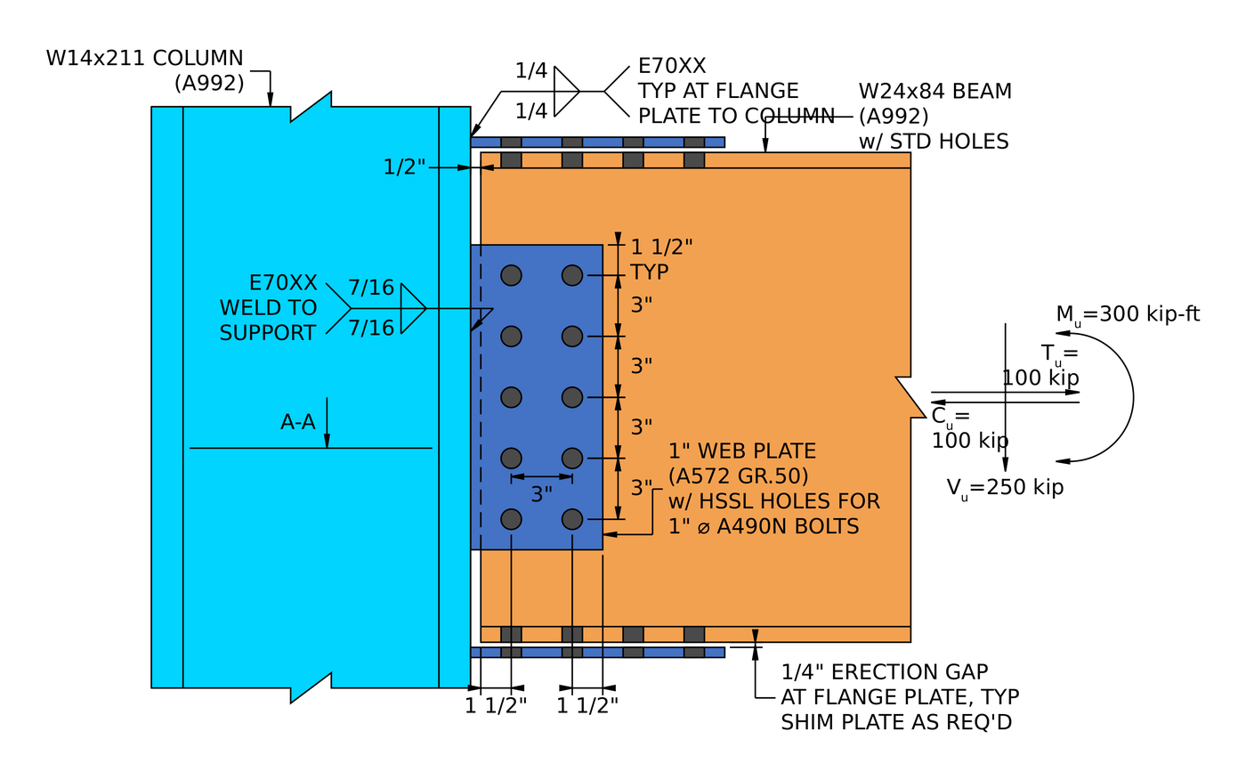
Höhe der Beispielverbindung. The flange plates are welded to the column with 1/4 in fillets and bolted to the beam flanges. The web plate is welded with 7/16 in fillets and bolted to the beam web. Da ist ein 1/4 in erection gap at each flange plate, filled with shims as required.
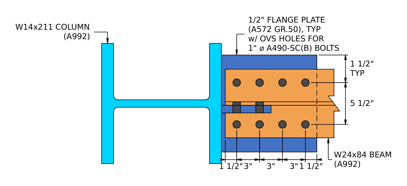
Abschnitt A-A. Each flange plate has two lines of four bolts at a 5 1/2 im Messgerät, in oversized holes in the plate and standard holes in the beam flange.
How do you design a flange plate moment connection? Die Schritte auf einen Blick
The flange plate connection is checked first, for the flange force from the moment and axial load. The web plate is checked second, for the shear.
- Check the detailing limits at the beam flange: Messgerät, Abstände und Randabstände.
- Find the flange force and check slip of the slip-critical bolts.
- Check bolt bearing and tear-out on the flange plate.
- Check bolt bearing and tear-out on the beam flange.
- Check block shear of the flange plate for three tear-out patterns.
- Check block shear of the beam flange.
- Check tension yielding and rupture of the flange plate.
- Check tension rupture of the beam, with shear lag.
- Check flexural rupture of the beam at the flange bolt holes.
- Check the flange plate in compression.
- Check the detailing limit at the column face.
- Check the fillet weld from the flange plate to the column flange.
- Check the column flange and web for the concentrated flange force.
- Check the detailing limits for the web plate.
- Check bolt group shear on the web plate.
- Check bolt bearing and tear-out on the web plate.
- Bolzenlager und Ausriss am Trägersteg prüfen.
- Schere kombinieren, Lager und Ausreißer pro Bolzen für die effektive Gruppenfestigkeit.
- Check block shear of the web plate.
- Check shear yielding and shear rupture of the web plate.
- Check the detailing limit for the web plate weld.
- Check the fillet weld from the web plate to the column flange.
Designeingaben für dieses Beispiel
Der Designcode ist AISC 360-16 LRFD. Abschnittseigenschaften stammen aus dem AISC-Handbuch.
| Artikel | Symbol | Wert |
|---|---|---|
| Faktorisierte vertikale Scherung | [mathin] V_{u} [mathin] | 250 kip |
| Factored axial tension | [mathin] T_{u} [mathin] | 100 kip |
| Factored axial compression | [mathin] C_{u} [mathin] | 100 kip |
| Factored strong-axis moment | [mathin] M_{ux} [mathin] | 300 kip-ft |
| Artikel | Symbol | Wert |
|---|---|---|
| Strahl | W24x84, A992 | |
| Strahltiefe | [mathin] d_{bm} [mathin] | 24.1 im |
| Balkenstegdicke | [mathin] t_{wb} [mathin] | 0.47 im |
| Breite des Trägerflansches / Dicke | [mathin] b_{fb},\ t_{fb} [mathin] | 9.02 im / 0.77 im |
| Strahlbereich | [mathin] A_{bm} [mathin] | 24.7 in² |
| Beam elastic section modulus | [mathin] S_{x} [mathin] | 196.46 in³ |
| Strahlausbeute / Zugspannung | [mathin] F_{yb},\ F_{ub} [mathin] | 50 KSI / 65 KSI |
| Spalte | W14x211, A992 | |
| Spaltentiefe | [mathin] d_{sup} [mathin] | 15.7 im |
| Column web thickness | [mathin] t_{ws} [mathin] | 0.98 im |
| Breite des Stützenflansches / Dicke | [mathin] b_{fs},\ t_{fs} [mathin] | 15.8 im / 1.56 im |
| Säulenbereich | [mathin] A_{sup} [mathin] | 62 in² |
| Column kdes / T dimension | [mathin] k_{des},\ T [mathin] | 2.16 im / 10 im |
| Säulenertrag / Zugspannung | [mathin] F_{ys},\ F_{us} [mathin] | 50 KSI / 65 KSI |
| Elastizitätsmodul | [mathin] E [mathin] | 29000 KSI |
| Flange plate connection | Symbol | Wert |
|---|---|---|
| Flanschplatte | PL 1/2 x 12 3/4 x 12 1/2, A572 Gr. 50 | |
| Plattenbreite / Länge / Dicke | [mathin] b_{fp},\ L_{fp},\ t_{fp} [mathin] | 12.75 im / 12.5 im / 0.5 im |
| Plattenausbeute / Zugspannung | [mathin] F_{yp},\ F_{up} [mathin] | 50 KSI / 65 KSI |
| Schrauben | 1 in A490-SC, Class B, one slip plane | |
| Nennzugkraft der Schraube / Scherbeanspruchung | [mathin] F_{nt},\ F_{nv} [mathin] | 113 KSI / 68 KSI |
| Löcher in der Platte / beam flange | Oversized (OVS) / Standard (STD) | |
| Bolzenreihen / Messgerät | [mathin] n_{r},\ g_{a} [mathin] | 2 / 5.5 im |
| Bolzensäulen / Spaltenabstand | [mathin] n_{c},\ s_{c} [mathin] | 4 / 3 im |
| Vertikal / horizontal edge distance on beam flange | [mathin] L_{ev,bf},\ L_{eh,bf} [mathin] | 1.76 im / 1.5 im |
| Vertikal / horizontal edge distance on flange plate | [mathin] L_{ev,fp},\ L_{eh,fp} [mathin] | 3.625 im / 1.5 im |
| Unbraced length of flange plate | [mathin] L_{k,fp} [mathin] | 3 im |
| Schweißen, flange plate to column | [mathin] W,\ F_{EXX} [mathin] | 1/4 im (0.25 im) Filet, E70XX, 70 KSI |
| Web plate connection | Symbol | Wert |
|---|---|---|
| Stegplatte (Einzelplatte) | PL 1 x 6 1/2 x 15, A572 Gr. 50 | |
| Plattenbreite / Tiefe / Dicke | [mathin] b_{p},\ d_{p},\ t_{p} [mathin] | 6.5 im / 15 im / 1 im |
| Plattenausbeute / Zugspannung | [mathin] F_{yp},\ F_{up} [mathin] | 50 KSI / 65 KSI |
| Schrauben | 1 in A490-N, Einzelschere | |
| Nennzugkraft der Schraube / Scherbeanspruchung | [mathin] F_{nt},\ F_{nv} [mathin] | 113 KSI / 68 KSI |
| Löcher in der Platte / Balkennetz | Horizontal kurzgeschlitzt (HSSL) / Standard (STD) | |
| Bolzenreihen / Reihenabstand | [mathin] n_{r},\ s_{r} [mathin] | 5 / 3 im |
| Bolzensäulen / Spaltenabstand | [mathin] n_{c},\ s_{c} [mathin] | 2 / 3 im |
| Abstand zwischen Trägersteg und Stütze | [mathin] clr [mathin] | 0.5 im |
| Horizontaler Randabstand am Trägersteg / Platte | [mathin] L_{eh,bm},\ L_{eh,pl} [mathin] | 1.5 im / 1.5 im |
| Vertikaler Randabstand auf der Platte | [mathin] L_{ev,pl} [mathin] | 1.5 im |
| Exzentrizität der Schraubengruppe | [mathin] e [mathin] | 3.5 im |
| Schweißen, web plate to column | [mathin] W,\ F_{EXX} [mathin] | 7/16 im (0.4375 im) fillet both sides, E70XX, 70 KSI |
Teil 1: the flange plate connection
Schritte 1 zu 13 check the flange plates, the beam flanges, the welds to the column and the column itself, all for the flange force worked out in Step 2.
Schritt 1: Detailing limits at the beam flange (AISC 360-16 J3.3, J3.4, J3.5)
Vor jeder Festigkeitsprüfung, Die Schraubenanordnung muss baubar sein und den Annahmen hinter den Festigkeitsgleichungen entsprechen. Zu enge Schrauben reißen zwischen den Löchern, and edges that are too close tear out.
The minimum bolt spacing is [mathin] 2\tfrac{2}{3} d_{b} [mathin] from J3.3. The minimum edge distance for a 1 in bolt is 1 1/4 aus Tabelle J3.4, which is the limit on the beam flange, where the holes are standard. The flange plate has oversized holes, so Table J3.5 adds 1/8 im, which brings its edge distance limits to 1.375 im. The gage has its own minimum, so that the two bolt lines fit across the flange with room to install the bolts.
[math] s_{min} = 2\tfrac{2}{3}\, d_{b} = 2.667 \times (1\,in) = 2.667\,in [math]
| Detaillierungslimit | Limit (im) | Tatsächlich (im) | DCR | Ergebnis |
|---|---|---|---|---|
| Minimum bolt gage | 4.875 | 5.500 | 0.886 | Die Hälfte der Wandhöhe von der Unterseite der Basis für den Fall des |
| Mindestabstand der Bolzensäulen | 2.667 | 3.000 | 0.889 | Die Hälfte der Wandhöhe von der Unterseite der Basis für den Fall des |
| Maximaler Schraubenspaltenabstand | 6.000 | 3.000 | 0.500 | Die Hälfte der Wandhöhe von der Unterseite der Basis für den Fall des |
| Minimaler vertikaler Randabstand der Platte | 1.375 | 3.625 | 0.379 | Die Hälfte der Wandhöhe von der Unterseite der Basis für den Fall des |
| Minimaler horizontaler Randabstand der Platte | 1.375 | 1.500 | 0.917 | Die Hälfte der Wandhöhe von der Unterseite der Basis für den Fall des |
| Minimaler vertikaler Randabstand des Strahls | 1.250 | 1.760 | 0.710 | Die Hälfte der Wandhöhe von der Unterseite der Basis für den Fall des |
| Minimaler horizontaler Randabstand des Strahls | 1.250 | 1.500 | 0.833 | Die Hälfte der Wandhöhe von der Unterseite der Basis für den Fall des |
Bei einem Mindestgrenzwert ist das Verhältnis Grenzwert zu Ist, und für ein Maximum liegt die tatsächliche Überschreitung des Grenzwerts vor. The governing row is the plate horizontal edge distance:
[math] DCR = \frac{1.375\,in}{1.5\,in} = 0.917 [math]
DCR = 0.917 < 1.0, in Ordnung
Schritt 2: Flange force and slip critical bolt strength (AISC 360-16 J3.8)
The moment is carried as a couple of equal and opposite forces in the two beam flanges, and the flange plate bolts have to carry that force without slipping. These bolts are slip-critical because the flange plate has oversized holes, which AISC 360-16 J3.2 allows only in slip-critical connections.
Flange force
The moment is divided by the distance between the beam flange centroids, [mathin] d_{bm} – t_{fb} [mathin]. The web plate is designed for shear only, so the axial load goes to the flange plates, half to each:
[math] P_{uF} = \frac{M_{ux}}{d_{bm} – t_{fb}} + \frac{P_{u}}{2} [math]
[math] P_{uF} = \frac{(300\,kip\text{-}ft)}{(24.1\,in) – (0.77\,in)} + \frac{(100\,kip)}{2} [math]
[math] P_{uF} = 204.31\,kip [math]
The axial tension and compression are both 100 kip, so the flange force is 204.31 kip either way: tension adds to the tension flange and compression adds to the compression flange. Every check in Part 1 uses this one value.
Slip resistance
Wo [mathin] \phi = 0.85 [mathin] is the resistance factor for oversized holes, [mathin] \mu = 0.5 [mathin] is the mean slip coefficient for Class B faying surfaces, [mathin] D_{u} = 1.13 [mathin] relates the mean installed pretension to the specified minimum, [mathin] h_{f} = 0.85 [mathin] is the filler factor, [mathin] T_{b} = 64\,kip [mathin] is the minimum pretension of a 1 in A490 bolt from Table J3.1, and there is [mathin] N_{s} = 1 [mathin] slip plane:
[math] \phi R_{n} = \phi\, \mu\, D_{u}\, h_{f}\, T_{b}\, N_{s}\, n_{r}\, n_{c} [math]
[math] \phi R_{n} = (0.85) \times (0.5) \times (1.13) \times (0.85) \times (64\,kip) \times (1) \times (2) \times (4) [math]
[math] \phi R_{n} = 209\,kip [math]
DCR = 204.31 kip / 209 kip = 0.978 < 1.0, in Ordnung
The filler factor of 0.85 is the J3.8 value for two or more fillers between the connected parts. The drawing calls for shims as required at the 1/4 in erection gap, so the design does not count on there being only one. Bei 0.978 this is one of the two tightest checks in the connection.
Schritt 3: Bolt bearing and tear-out on the flange plate (AISC 360-16 J3.10)
Slip-critical bolts must also have enough strength as bearing bolts, in case the joint does slip. Each bolt pushes on the edge of its hole in the plate. Entweder verformt sich die Platte am Loch (Lager, begrenzt auf 2.4 d t Fu) or tears a strip out to the next hole or to the end of the plate (herausreißen, 1.2 lc t Fu). The bolts nearest the end of the plate have the shortest clear distance, so they are the weak ones.
Clear distance for the end bolts, mit [mathin] d_{h} = 1.25\,in [mathin], the oversized hole dimension along the member length:
[math] l_{c1} = L_{eh,fp} – \frac{d_{h}}{2} = (1.5\,in) – \frac{(1.25\,in)}{2} = 0.875\,in [math]
Clear distance between the other bolts:
[math] l_{c2} = s_{c} – d_{h} = (3\,in) – (1.25\,in) = 1.75\,in [math]
The end bolt in each of the two lines uses [mathin] l_{c1} [mathin], and the other three in each line use [mathin] l_{c2} [mathin]:
[math] \phi R_{n} = \phi \left[ \min\left(1.2\, l_{c1},\, 2.4\, d_{b}\right) t_{fp} F_{up}\, n_{r} + \min\left(1.2\, l_{c2},\, 2.4\, d_{b}\right) t_{fp} F_{up}\, n_{r} \left( n_{c} – 1 \right) \right] [math]
[math] \phi R_{n} = (0.75) \times \left[ \min\left(1.2 \times 0.875\,in,\, 2.4 \times 1\,in\right)(0.5\,in)(65\,ksi)(2) + \min\left(1.2 \times 1.75\,in,\, 2.4 \times 1\,in\right)(0.5\,in)(65\,ksi)(2)(4 – 1) \right] [math]
[math] \phi R_{n} = 358.31\,kip [math]
DCR = 204.31 kip / 358.31 kip = 0.570 < 1.0, in Ordnung
Schritt 4: Bolt bearing and tear-out on the beam flange (AISC 360-16 J3.10)
The same check applies to the beam flange, which has standard holes ([mathin] d_{h} = 1.125\,in [mathin]) and is thicker than the plate.
[math] l_{c1} = L_{eh,bf} – \frac{d_{h}}{2} = (1.5\,in) – \frac{(1.125\,in)}{2} = 0.9375\,in [math]
[math] l_{c2} = s_{c} – d_{h} = (3\,in) – (1.125\,in) = 1.875\,in [math]
[math] \phi R_{n} = \phi \left[ \min\left(1.2\, l_{c1},\, 2.4\, d_{b}\right) t_{fb} F_{ub}\, n_{r} + \min\left(1.2\, l_{c2},\, 2.4\, d_{b}\right) t_{fb} F_{ub}\, n_{r} \left( n_{c} – 1 \right) \right] [math]
[math] \phi R_{n} = (0.75) \times \left[ \min\left(1.2 \times 0.9375\,in,\, 2.4 \times 1\,in\right)(0.77\,in)(65\,ksi)(2) + \min\left(1.2 \times 1.875\,in,\, 2.4 \times 1\,in\right)(0.77\,in)(65\,ksi)(2)(4 – 1) \right] [math]
[math] \phi R_{n} = 591.22\,kip [math]
DCR = 204.31 kip / 591.22 kip = 0.346 < 1.0, in Ordnung
Schritt 5: Block shear of the flange plate (AISC 360-16 J4.3)
A block of the flange plate can tear out along the bolt lines: shear along a line of holes plus tension across the plate. With two bolt lines there are three ways for this to happen, and the weakest one governs. Jedes Loch fügt hinzu 1/16 auf Beschädigungen beim Stanzen (B4.3), und [mathin] d_{h} = 1.25\,in [mathin] for the oversized holes in both directions.
L pattern: one shear plane, tension across the bolts to one edge
[math] A_{nt} = t_{fp} \left[ (n_{r} – 2)\, s_{r} + g_{a} + L_{ev,fp} – (n_{r} – 0.5)\left( d_{h} + 0.0625\,in \right) \right] [math]
[math] A_{nt} = (0.5\,in) \times \left[ (2 – 2)(3\,in) + 5.5\,in + 3.625\,in – (2 – 0.5)(1.25\,in + 0.0625\,in) \right] = 3.5781\,in^{2} [math]
[math] A_{gv} = t_{fp} \left[ L_{eh,fp} + (n_{c} – 1)\, s_{c} \right] = (0.5\,in) \times \left[ 1.5\,in + (4 – 1)(3\,in) \right] = 5.25\,in^{2} [math]
[math] A_{nv} = t_{fp} \left[ L_{eh,fp} + (n_{c} – 1)\, s_{c} – (n_{c} – 0.5)\left( d_{h} + 0.0625\,in \right) \right] = (0.5\,in) \times \left[ 1.5\,in + (3)(3\,in) – (3.5)(1.3125\,in) \right] = 2.9531\,in^{2} [math]
Mit [mathin] U_{bs} = 1 [mathin] für gleichmäßige Spannung:
[math] \phi R_{n} = \phi \left( 0.6\, F_{up} A_{nv} + U_{bs} F_{up} A_{nt} \right) \le \phi \left( 0.6\, F_{yp} A_{gv} + U_{bs} F_{up} A_{nt} \right) [math]
[math] \phi R_{n} = (0.75) \left( 0.6 \times 65 \times 2.9531 + 1 \times 65 \times 3.5781 \right) \le (0.75) \left( 0.6 \times 50 \times 5.25 + 1 \times 65 \times 3.5781 \right) [math]
[math] \phi R_{n} = 260.81\,kip [math]
U pattern: two shear planes, tension between the bolt lines
[math] A_{gv} = 2\, t_{fp} \left[ L_{eh,fp} + (n_{c} – 1)\, s_{c} \right] = 2 \times (0.5\,in) \times \left[ 1.5\,in + (3)(3\,in) \right] = 10.5\,in^{2} [math]
[math] A_{nv} = 2\, t_{fp} \left[ L_{eh,fp} + (n_{c} – 1)\, s_{c} – (n_{c} – 0.5)\left( d_{h} + 0.0625\,in \right) \right] = 5.9062\,in^{2} [math]
[math] A_{nt} = t_{fp} \left[ (n_{r} – 2)\, s_{r} + g_{a} – (n_{r} – 1)\left( d_{h} + 0.0625\,in \right) \right] = (0.5\,in) \times \left[ 0 + 5.5\,in – (1)(1.3125\,in) \right] = 2.0937\,in^{2} [math]
[math] \phi R_{n} = (0.75) \left( 0.6 \times 65 \times 5.9062 + 1 \times 65 \times 2.0937 \right) \le (0.75) \left( 0.6 \times 50 \times 10.5 + 1 \times 65 \times 2.0937 \right) = 274.83\,kip [math]
2L pattern: two shear planes, tension from each bolt line to its edge
[math] A_{nt} = 2\, t_{fp} \left[ L_{ev,fp} – 0.5\left( d_{h} + 0.0625\,in \right) \right] = 2 \times (0.5\,in) \times \left[ 3.625\,in – 0.5 \times (1.3125\,in) \right] = 2.9687\,in^{2} [math]
[math] \phi R_{n} = (0.75) \left( 0.6 \times 65 \times 5.9062 + 1 \times 65 \times 2.9687 \right) \le (0.75) \left( 0.6 \times 50 \times 10.5 + 1 \times 65 \times 2.9687 \right) = 317.48\,kip [math]
Governing block shear
[math] \phi R_{n} = \min\left( 260.81\,kip,\, 274.83\,kip,\, 317.48\,kip \right) = 260.81\,kip [math]
DCR = 204.31 kip / 260.81 kip = 0.783 < 1.0, in Ordnung
The L pattern governs because it has only one shear plane. Mit der 12.75 in plate is wider than the 9.02 in beam flange, which gives the outer strips plenty of tension area in the 2L pattern.
Schritt 6: Block shear of the beam flange (AISC 360-16 J4.3)
The beam flange can tear out the same way. Its edges are only 1.76 in outside the bolt lines, so the critical block is the 2L pattern: the two outer strips of flange shear along the bolt lines and pull away in tension.
[math] A_{nt} = t_{fb} \left[ b_{fb} – g_{a} – (n_{r} – 1)\left( d_{h} + 0.0625\,in \right) \right] = (0.77\,in) \times \left[ 9.02\,in – 5.5\,in – (1)(1.125\,in + 0.0625\,in) \right] = 1.796\,in^{2} [math]
[math] A_{gv} = 2\, t_{fb} \left[ L_{eh,bf} + (n_{c} – 1)\, s_{c} \right] = 2 \times (0.77\,in) \times \left[ 1.5\,in + (3)(3\,in) \right] = 16.17\,in^{2} [math]
[math] A_{nv} = 2\, t_{fb} \left[ L_{eh,bf} + (n_{c} – 1)\, s_{c} – (n_{c} – 0.5)\left( d_{h} + 0.0625\,in \right) \right] = 2 \times (0.77\,in) \times \left[ 10.5\,in – (3.5)(1.1875\,in) \right] = 9.7694\,in^{2} [math]
[math] \phi R_{n} = (0.75) \left( 0.6 \times 65 \times 9.7694 + 1 \times 65 \times 1.796 \right) \le (0.75) \left( 0.6 \times 50 \times 16.17 + 1 \times 65 \times 1.796 \right) [math]
[math] \phi R_{n} = 373.31\,kip [math]
DCR = 204.31 kip / 373.31 kip = 0.547 < 1.0, in Ordnung
Schritt 7: Tension yielding and rupture of the flange plate (AISC 360-16 J4.1)
On the tension side, the flange plate is a short tension member. Its gross section must not yield, and its net section through the row of holes must not rupture.
Tension yielding (Gl. J4-1)
[math] \phi R_{n,ty} = \phi\, F_{yp}\, t_{fp}\, b_{fp} = (0.9) \times (50\,ksi) \times (0.5\,in) \times (12.75\,in) = 286.88\,kip [math]
Tension rupture (Gl. J4-2)
[math] \phi R_{n,tr} = \phi\, F_{up}\, t_{fp} \left[ b_{fp} – n_{r}\left( d_{h} + 0.0625\,in \right) \right] [math]
[math] \phi R_{n,tr} = (0.75) \times (65\,ksi) \times (0.5\,in) \times \left[ 12.75\,in – (2) \times (1.25\,in + 0.0625\,in) \right] = 246.8\,kip [math]
[math] \phi R_{n} = \min\left( 286.88\,kip,\, 246.8\,kip \right) = 246.8\,kip [math]
DCR = 204.31 kip / 246.8 kip = 0.828 < 1.0, in Ordnung
Schritt 8: Tension rupture of the beam with shear lag (AISC 360-16 D3, J4.1)
The flange force has to get into the beam as well. Half the beam, a WT made of one flange and half the web, is treated as the tension member. The bolts connect only the flange, so the web lags behind in picking up stress, and the shear lag factor U reduces the effective net area.
From Table D3.1 case 2, wo [mathin] \bar{y} = 3.0217\,in [mathin] is the distance from the flange to the centroid of the WT and l is the length of the connection, from the first bolt column to the last:
[math] U = 1 – \frac{\bar{y}}{l} = 0.66439 [math]
[math] \phi R_{n,tr} = \phi\, F_{ub}\, U \left[ 0.5\, A_{bm} – n_{r}\left( d_{h} + 0.0625\,in \right) t_{fb} \right] [math]
[math] \phi R_{n,tr} = (0.75) \times (65\,ksi) \times (0.66439) \times \left[ 0.5 \times (24.7\,in^{2}) – (2) \times (1.125\,in + 0.0625\,in) \times (0.77\,in) \right] [math]
[math] \phi R_{n,tr} = 340.78\,kip [math]
DCR = 204.31 kip / 340.78 kip = 0.600 < 1.0, in Ordnung
Schritt 9: Flexural rupture of the beam at the flange bolt holes (AISC 360-16 F13.1)
The bolt holes take material out of the beam’s tension flange right where the moment is largest. F13.1 checks whether those holes reduce the beam’s flexural strength, and if they do, by how much.
Gross and net area of the tension flange
[math] A_{fg} = b_{fb}\, t_{fb} = (9.02\,in) \times (0.77\,in) = 6.9454\,in^{2} [math]
[math] A_{fn} = A_{fg} – n_{r}\left( d_{h} + 0.0625\,in \right) t_{fb} = (6.9454\,in^{2}) – (2) \times (1.125\,in + 0.0625\,in) \times (0.77\,in) = 5.1166\,in^{2} [math]
Does tensile rupture apply?
[math] \frac{F_{y}}{F_{u}} = \frac{50\,ksi}{65\,ksi} = 0.76923 \le 0.8 \;\Rightarrow\; Y_{t} = 1 [math]
[math] F_{u} A_{fn} = (65\,ksi) \times (5.1166\,in^{2}) = 332.58\,kip [math]
[math] Y_{t} F_{y} A_{fg} = (1) \times (50\,ksi) \times (6.9454\,in^{2}) = 347.27\,kip [math]
weil [mathin] F_{u} A_{fn} \lt Y_{t} F_{y} A_{fg} [mathin], the net flange ruptures before the gross flange yields, so the limit state of tensile rupture applies.
Flexural strength at the holes (Gl. F13-1)
[math] M_{n} = \frac{F_{ub} A_{fn}}{A_{fg}}\, S_{x} = \frac{(65\,ksi) \times (5.1166\,in^{2})}{(6.9454\,in^{2})} \times (196.46\,in^{3}) = 783.95\,kip\text{-}ft [math]
As a flange force, to compare with [mathin] P_{uF} [mathin]:
[math] \phi R_{n} = \frac{\phi\, M_{n}}{d_{bm} – t_{fb}} = \frac{(0.9) \times (783.95\,kip\text{-}ft)}{(24.1\,in) – (0.77\,in)} = 362.91\,kip [math]
DCR = 204.31 kip / 362.91 kip = 0.563 < 1.0, in Ordnung
Schritt 10: Compression strength of the flange plate (AISC 360-16 J4.4)
On the compression side the flange plate is a short column. If it is stocky enough, it reaches its yield load without buckling, und AISC 360-16 J4.4 lets you skip the full Chapter E column check.
The report takes the unbraced length of the plate as [mathin] L_{k,fp} = 3\,in [mathin] mit [mathin] K = 1.2 [mathin], the recommended design value in Commentary Table C-A-7.1 for a member fixed against rotation at both ends but free to translate at one. For a rectangular plate, [mathin] r = t_{fp} / \sqrt{12} [mathin]:
[math] \frac{K L}{r} = \frac{(1.2) \times (3\,in)}{(0.5\,in) / \sqrt{12}} = 24.942 \le 25 [math]
Since KL/r is no more than 25, Gl. J4-6 applies:
[math] \phi R_{n} = \phi\, F_{yp}\, t_{fp}\, b_{fp} = (0.9) \times (50\,ksi) \times (0.5\,in) \times (12.75\,in) = 286.88\,kip [math]
DCR = 204.31 kip / 286.88 kip = 0.712 < 1.0, in Ordnung
The ratio of 24.942 is just under the limit of 25. A thinner plate or a longer unbraced length would push the plate into the Chapter E buckling equations.
Schritt 11: Detailing limit at the column face
The flange plate weld sits in the gap between the column flange and the end of the beam, so the weld cannot be larger than the beam clearance.
[math] DCR = \frac{W}{clr} = \frac{0.25\,in}{0.5\,in} = 0.5 [math]
DCR = 0.500 < 1.0, in Ordnung
Schritt 12: Fillet weld capacity, flange plate to column flange (AISC 360-16 J2.4)
The whole flange force passes through the fillet welds that join the flange plate to the column. Their fillet weld capacity depends on size, Länge und Belastungsrichtung. Das Grundmetall auf beiden Seiten der Schweißnaht, here the plate and the column flange, kann auch begrenzen, wie viel von der Schweißnahtgröße zählt.
Grundmetallbeschränkung für die Schweißnahtgröße (AISC-Handbuch Gl. 9-2)
[math] D_{max} = \frac{ \min\left( \frac{t_{fp}}{2} F_{up},\; t_{fs} F_{us} \right) }{3.09\,kip/in \times \left( F_{EXX} / 70\,ksi \right)} = \frac{ \min\left( (0.25\,in)(65\,ksi),\; (1.56\,in)(65\,ksi) \right) }{(3.09\,kip/in)(1)} = 5.2589 [math]
So up to 5.26/16 in of weld size counts. Mit der 1/4 im (4/16 im) weld is below that, so its full size is used.
Effektive Länge
The weld runs across the plate width on both faces of the plate, each line reduced by 2W at the ends. The plate is narrower than the column flange, so the plate width sets the length:
[math] L_{w} = 2 \left[ \min\left( b_{fp},\, b_{fs} \right) – 2W \right] = 2 \times \left[ \min\left( 12.75\,in,\, 15.8\,in \right) – 2 \times (0.25\,in) \right] = 24.5\,in [math]
Schweißfestigkeit
The flange force acts perpendicular to the weld lines, Also [mathin] \theta = 90^{\circ} [mathin] and the directional factor [mathin] 1 + 0.5 \sin^{1.5}\theta [mathin] ist 1.5:
[math] \phi R_{n} = \phi\, 0.6\, F_{EXX} \frac{\sqrt{2}}{2} \min\left( W,\, \frac{D_{max}}{16} \right) (1.5)\, L_{w} [math]
[math] \phi R_{n} = (0.75) \times 0.6 \times (70\,ksi) \times \frac{\sqrt{2}}{2} \times (0.25\,in) \times (1.5) \times (24.5\,in) [math]
[math] \phi R_{n} = 204.64\,kip [math]
DCR = 204.31 kip / 204.64 kip = 0.998 < 1.0, in Ordnung
This is the governing check of the whole connection. Mit der 1/4 in weld carries the flange force with almost nothing to spare, and only because the 1.5 directional factor applies. Without it, the weld would need to be about 3/8 im.
Schritt 13: Column flange and web under the flange force (AISC 360-16 J10)
Each flange plate delivers its force to the column as a concentrated load. The column flange can bend, the web can yield, cripple or buckle under it, and the panel zone has to carry the moment as shear. If any of these fail, the column needs stiffeners or a doubler plate, or a heavier section.
Flange local bending (Gl. J10-1)
[math] \phi R_{n,flb} = \phi\, 6.25\, F_{ys}\, t_{fs}^{2} = (0.9) \times 6.25 \times (50\,ksi) \times (1.56\,in)^{2} = 684.45\,kip [math]
Web compression buckling (Gl. J10-8)
The report uses the column’s T dimension, [mathin] T_{sup} = 10\,in [mathin], for the web depth in this equation, mit [mathin] Q_{f} = 1 [mathin]:
[math] \phi R_{n,wcb} = \phi \left( \frac{24\, t_{ws}^{3} \sqrt{E\, F_{ys}}}{T_{sup}} \right) Q_{f} = (0.9) \times \left( \frac{24 \times (0.98\,in)^{3} \times \sqrt{(29000\,ksi) \times (50\,ksi)}}{(10\,in)} \right) \times (1) = 2448\,kip [math]
Strictly, J10.5 applies when compressive forces act on both column flanges at the same level, as when beams frame in from both sides. Checking it for a one-sided connection is conservative, and here it is nowhere near governing.
Web local crippling (Gl. J10-4)
The length of bearing [mathin] l_{b} = 0.5\,in [mathin] is the flange plate thickness:
[math] \phi R_{n,wlc} = \phi\, 0.8\, t_{ws}^{2} \left[ 1 + 3 \left( \frac{l_{b}}{d_{sup}} \right) \left( \frac{t_{ws}}{t_{fs}} \right)^{1.5} \right] \sqrt{\frac{E\, F_{ys}\, t_{fs}}{t_{ws}}}\, Q_{f} [math]
[math] \phi R_{n,wlc} = (0.75) \times 0.8 \times (0.98\,in)^{2} \times \left[ 1 + 3 \times \left( \frac{0.5\,in}{15.7\,in} \right) \times \left( \frac{0.98\,in}{1.56\,in} \right)^{1.5} \right] \times \sqrt{\frac{(29000\,ksi) \times (50\,ksi) \times (1.56\,in)}{(0.98\,in)}} \times (1) = 917.11\,kip [math]
Web local yielding (Gl. J10-2)
[math] \phi R_{n,wly} = \phi\, F_{ys}\, t_{ws} \left( 5\, k_{des} + l_{b} \right) = (1) \times (50\,ksi) \times (0.98\,in) \times \left( 5 \times 2.16\,in + 0.5\,in \right) = 553.7\,kip [math]
Panel zone web shear (Gl. J10-9)
[math] \phi R_{n,wpz} = \phi\, 0.6\, F_{ys}\, d_{sup}\, t_{ws} = (0.9) \times 0.6 \times (50\,ksi) \times (15.7\,in) \times (0.98\,in) = 415.42\,kip [math]
Governing column strength
[math] \phi R_{n} = \min\left( 684.45,\, 2448,\, 917.11,\, 553.7,\, 415.42 \right) = 415.42\,kip [math]
DCR = 204.31 kip / 415.42 kip = 0.492 < 1.0, in Ordnung
The W14x211 column has a 1.56 in flange and a 0.98 im Web, so it needs no stiffeners or doubler plate for this flange force. Panel zone shear governs the column checks.
Teil 2: the web plate connection
Schritte 14 zu 22 check the web plate, a single plate connection that carries the 250 kip shear. Because the flange plates make the joint fully restrained, the web plate does not have to rotate like a simple shear tab, and the checks that exist only to keep a shear tab flexible are not part of this design.
Schritt 14: Detailing limits for the web plate (AISC 360-16 J3.3, J3.4, J3.5)
The web plate bolt layout has to meet the same spacing and edge distance rules, and the plate has to be deep enough to stabilise the beam web while still fitting between the beam flanges.
The plate has horizontal short-slotted holes. The horizontal edge distance is measured along the slot, so Table J3.5 adds 1/8 in and the limit becomes 1.375 im. The vertical edge distance is measured across the slot and stays at 1.25 im.
| Detaillierungslimit | Limit (im) | Tatsächlich (im) | DCR | Ergebnis |
|---|---|---|---|---|
| Mindestabstand der Schraubenreihen | 2.667 | 3.000 | 0.889 | Die Hälfte der Wandhöhe von der Unterseite der Basis für den Fall des |
| Maximaler Schraubenreihenabstand | 6.000 | 3.000 | 0.500 | Die Hälfte der Wandhöhe von der Unterseite der Basis für den Fall des |
| Mindestabstand der Bolzensäulen | 2.667 | 3.000 | 0.889 | Die Hälfte der Wandhöhe von der Unterseite der Basis für den Fall des |
| Maximaler Schraubenspaltenabstand | 6.000 | 3.000 | 0.500 | Die Hälfte der Wandhöhe von der Unterseite der Basis für den Fall des |
| Minimaler vertikaler Randabstand der Platte | 1.250 | 1.500 | 0.833 | Die Hälfte der Wandhöhe von der Unterseite der Basis für den Fall des |
| Minimaler horizontaler Randabstand der Platte | 1.375 | 1.500 | 0.917 | Die Hälfte der Wandhöhe von der Unterseite der Basis für den Fall des |
| Minimaler horizontaler Randabstand des Strahls | 1.250 | 1.500 | 0.833 | Die Hälfte der Wandhöhe von der Unterseite der Basis für den Fall des |
| Mindestverbindungstiefe | 10.000 | 15.000 | 0.667 | Die Hälfte der Wandhöhe von der Unterseite der Basis für den Fall des |
| Maximale Verbindungstiefe | 20.750 | 15.000 | 0.723 | Die Hälfte der Wandhöhe von der Unterseite der Basis für den Fall des |
[math] DCR = \frac{1.375\,in}{1.5\,in} = 0.917 [math]
DCR = 0.917 < 1.0, in Ordnung
Schritt 15: Bolt group shear on the web plate (AISC 360-16 J3.6)
The ten web bolts share the 250 kip shear. In a simple shear tab, the eccentricity of the reaction would reduce the group to fewer than ten bolts’ Wert der Stärke. Here the report uses a bolt group coefficient C = 10, the full bolt count, because the end moment is taken by the flange plates and the web bolts carry the shear directly.
Wo [mathin] \phi = 0.75 [mathin], [mathin] F_{nv} = 68\,ksi [mathin] for an A490-N bolt, [mathin] N_{s} = 1 [mathin] shear plane, und [mathin] h_{f} = 1 [mathin] weil es keine Füllstoffe gibt (J5.2(ein)):
[math] h_{f} = 1 – 0.4 \left( t – 0.25\,in \right) = 1 – 0.4 \left( 0\,in – 0.25\,in \right) \le 1 \;\Rightarrow\; h_{f} = 1 [math]
[math] \phi R_{n} = \phi\, F_{nv}\, \frac{\pi}{4} d_{b}^{2}\, N_{s}\, C\, h_{f} [math]
[math] \phi R_{n} = (0.75) \times (68\,ksi) \times \frac{\pi}{4} (1\,in)^{2} \times (1) \times (10) \times (1) [math]
[math] \phi R_{n} = 400.55\,kip [math]
DCR = 250 kip / 400.55 kip = 0.624 < 1.0, in Ordnung
For a bolt group where eccentricity does reduce C, bleibt die Schraubengruppenberechnung mit ICOR shows how the coefficient is found.
Schritt 16: Bolt bearing and tear-out on the web plate (AISC 360-16 J3.10)
Each bolt pushes down on its hole in the web plate. The bottom bolt in each line has the short clear distance to the plate edge, also ist es der Schwache. Die Schlitze verlaufen horizontal und die Belastung erfolgt vertikal, so the hole dimension across the slot, [mathin] d_{h} = 1.125\,in [mathin], wird eingesetzt.
[math] l_{c1} = L_{ev,pl} – \frac{d_{h}}{2} = (1.5\,in) – \frac{(1.125\,in)}{2} = 0.9375\,in [math]
[math] l_{c2} = s_{r} – d_{h} = (3\,in) – (1.125\,in) = 1.875\,in [math]
One line of bolts is worked out and scaled by [mathin] C / n_{r} = 10 / 5 [mathin] for the two lines:
[math] \phi R_{n} = \phi \left[ \min\left(1.2\, l_{c1},\, 2.4\, d_{b}\right) t_{p} F_{up} + \min\left(1.2\, l_{c2},\, 2.4\, d_{b}\right) t_{p} F_{up} \left( n_{r} – 1 \right) \right] \frac{C}{n_{r}} [math]
[math] \phi R_{n} = (0.75) \times \left[ \min\left(1.125,\, 2.4\right)(1)(65) + \min\left(2.25,\, 2.4\right)(1)(65)(5 – 1) \right] \times \frac{10}{5} [math]
[math] \phi R_{n} = 987.19\,kip [math]
DCR = 250 kip / 987.19 kip = 0.253 < 1.0, in Ordnung
Schritt 17: Bolzenlagerung und Ausriss am Trägersteg (AISC 360-16 J3.10)
Die gleiche Prüfung gilt für den Balkensteg. Der Träger ist nicht abgedeckt und seine Flansche sind weit von den Bolzen entfernt, Es gibt also keine Kante, an der man herausreißen kann, und jeder Bolzen trägt wie ein innerer Bolzen.
[math] l_{c2} = s_{r} – d_{h} = (3\,in) – (1.125\,in) = 1.875\,in [math]
[math] \phi R_{n} = \phi\, \min\left(1.2\, l_{c2},\, 2.4\, d_{b}\right) t_{wb} F_{ub}\, C [math]
[math] \phi R_{n} = (0.75) \times \min\left(1.2 \times 1.875\,in,\, 2.4 \times 1\,in\right) \times (0.47\,in) \times (65\,ksi) \times (10) [math]
[math] \phi R_{n} = 515.53\,kip [math]
DCR = 250 kip / 515.53 kip = 0.485 < 1.0, in Ordnung
Schritt 18: Effective strength of the web bolt group (AISC 360-16 J3.6 Kommentar)
In practice each bolt delivers the least of its shear strength and its bearing or tear-out strength in each ply it passes through, und die Gruppenstärke ist die Summe dieser Werte pro Bolzen.
[math] \phi r_{v} = \phi\, F_{nv}\, \frac{\pi}{4} d_{b}^{2}\, N_{s}\, h_{f} = (0.75) \times (68\,ksi) \times \frac{\pi}{4} (1\,in)^{2} \times (1) \times (1) = 40.055\,kip [math]
[math] \phi r_{n1e} = \phi\, \min\left(1.2\, l_{c1},\, 2.4\, d_{b}\right) t_{p} F_{up} = (0.75) \times \min\left(1.125\,in,\, 2.4\,in\right) \times (1\,in) \times (65\,ksi) = 54.844\,kip [math]
[math] \phi r_{n1i} = \phi\, \min\left(1.2\, l_{c2},\, 2.4\, d_{b}\right) t_{p} F_{up} = (0.75) \times \min\left(2.25\,in,\, 2.4\,in\right) \times (1\,in) \times (65\,ksi) = 109.69\,kip [math]
[math] \phi r_{n2} = \phi\, \min\left(1.2\, l_{c2},\, 2.4\, d_{b}\right) t_{wb} F_{ub} = (0.75) \times \min\left(2.25\,in,\, 2.4\,in\right) \times (0.47\,in) \times (65\,ksi) = 51.553\,kip [math]
Die Schrauben werden von oben in der Zeile nummeriert, Also verflucht 5 ist der Randbolzen auf der Platte:
| Bolzen | Bolzenscherung (kip) | Bodenkohäsion an der Pfahlspitze q / herausreißen, Platte (kip) | Bodenkohäsion an der Pfahlspitze q / herausreißen, Balkennetz (kip) | Effektive Stärke (kip) |
|---|---|---|---|---|
| 1 | 40.06 | 109.69 | 51.55 | 40.06 |
| 2 | 40.06 | 109.69 | 51.55 | 40.06 |
| 3 | 40.06 | 109.69 | 51.55 | 40.06 |
| 4 | 40.06 | 109.69 | 51.55 | 40.06 |
| 5 | 40.06 | 54.84 | 51.55 | 40.06 |
[math] \sum \phi r_{eff} = n_{1}\, \phi r_{eff,1} + n_{2}\, \phi r_{eff,2} = (4) \times (40.055\,kip) + (1) \times (40.055\,kip) = 200.28\,kip [math]
[math] \phi R_{n,eff} = \frac{C}{n_{r}} \sum \phi r_{eff} = \frac{10}{5} \times (200.28\,kip) = 400.55\,kip [math]
DCR = 250 kip / 400.55 kip = 0.624 < 1.0, in Ordnung
Every bolt is limited by AISC bolt shear, not by bolt bearing. Mit der 1 in plate and the 0.47 in web are thick enough that the bolts give out first, Die effektive Festigkeit entspricht also der Scherfestigkeit der Schraubengruppe aus Schritt 15. Sie können die gleiche Verbindung im ausführen Kostenloser Verbindungsdesign-Rechner and try a thinner web plate to see when bearing starts to govern.
Schritt 19: Block shear of the web plate (AISC 360-16 J4.3)
A block of the web plate can tear out along the bolts: shear down the outer line of holes plus tension across the two bolt columns to the plate’s free edge.
The net tension area runs along the slots, es wird also die Schlitzlänge verwendet, [mathin] d_{h} = 1.3125\,in [mathin]:
[math] A_{nt} = t_{p} \left[ (n_{c} – 1)\, s_{c} + L_{eh,pl} – (n_{c} – 0.5)\left( d_{h} + 0.0625\,in \right) \right] = (1\,in) \times \left[ (1)(3\,in) + 1.5\,in – (1.5)(1.3125\,in + 0.0625\,in) \right] = 2.4375\,in^{2} [math]
Gross and net shear areas, mit [mathin] d_{h} = 1.125\,in [mathin] über die Schlitze:
[math] A_{gv} = t_{p} \left[ L_{ev,pl} + (n_{r} – 1)\, s_{r} \right] = (1\,in) \times \left[ 1.5\,in + (4)(3\,in) \right] = 13.5\,in^{2} [math]
[math] A_{nv} = t_{p} \left[ d_{p} – L_{ev,pl} – (n_{r} – 0.5)\left( d_{h} + 0.0625\,in \right) \right] = (1\,in) \times \left[ 15\,in – 1.5\,in – (4.5)(1.1875\,in) \right] = 8.1563\,in^{2} [math]
Mit zwei Riegelsäulen, the column nearer the edge carries more of the tension than the other, so the stress across the tension area is not uniform and [mathin] U_{bs} = 0.5 [mathin]:
[math] \phi R_{n} = \phi \left( 0.6\, F_{up} A_{nv} + U_{bs} F_{up} A_{nt} \right) \le \phi \left( 0.6\, F_{yp} A_{gv} + U_{bs} F_{up} A_{nt} \right) [math]
[math] \phi R_{n} = (0.75) \left( 0.6 \times 65 \times 8.1563 + 0.5 \times 65 \times 2.4375 \right) \le (0.75) \left( 0.6 \times 50 \times 13.5 + 0.5 \times 65 \times 2.4375 \right) [math]
[math] \phi R_{n} = 297.98\,kip [math]
DCR = 250 kip / 297.98 kip = 0.839 < 1.0, in Ordnung
Schritt 20: Shear yielding and shear rupture of the web plate (AISC 360-16 J4.2)
The full shear passes through the web plate. Der Bruttoquerschnitt darf nicht nachgeben, und der Netzabschnitt durch die Bolzenlöcher darf nicht reißen.
Scherung nachgebend (Gl. J4-3)
[math] A_{gv} = d_{p}\, t_{p} = (15\,in) \times (1\,in) = 15\,in^{2} [math]
[math] \phi R_{n,sy} = \phi\, 0.6\, F_{yp} A_{gv} = (1.00) \times 0.6 \times (50\,ksi) \times (15\,in^{2}) = 450\,kip [math]
Scherbruch (Gl. J4-4)
[math] A_{nv} = t_{p} \left[ d_{p} – n_{r}\left( d_{h} + 0.0625\,in \right) \right] = (1\,in) \times \left[ 15\,in – (5) \times (1.125\,in + 0.0625\,in) \right] = 9.0625\,in^{2} [math]
[math] \phi R_{n,sr} = \phi\, 0.6\, F_{up} A_{nv} = (0.75) \times 0.6 \times (65\,ksi) \times (9.0625\,in^{2}) = 265.08\,kip [math]
[math] \phi R_{n} = \min\left( 450\,kip,\, 265.08\,kip \right) = 265.08\,kip [math]
DCR = 250 kip / 265.08 kip = 0.943 < 1.0, in Ordnung
Shear rupture governs the web plate. Five holes take almost 40% out of the shear area of the 15 in plate.
Schritt 21: Detailing limit for the web plate weld
Like the flange plate weld, the web plate weld has to fit in the gap between the column flange and the end of the beam.
[math] DCR = \frac{W}{clr} = \frac{0.438\,in}{0.5\,in} = 0.876 [math]
DCR = 0.876 < 1.0, in Ordnung
Schritt 22: Fillet weld capacity, web plate to column flange (AISC 360-16 J2.4)
Zuletzt, the two fillet welds on the web plate have to carry the shear into the column flange.
Grundmetallbeschränkung für die Schweißnahtgröße (AISC-Handbuch Gl. 9-2)
Die Platte ist beidseitig verschweißt, Somit steht jeder Schweißnaht die Hälfte ihrer Dicke zur Verfügung:
[math] D_{max} = \frac{ \min\left( \frac{t_{p}}{2} F_{up},\; t_{fs} F_{us} \right) }{3.09\,kip/in \times \left( F_{EXX} / 70\,ksi \right)} = \frac{ \min\left( (0.5\,in)(65\,ksi),\; (1.56\,in)(65\,ksi) \right) }{(3.09\,kip/in)(1)} = 10.518 [math]
Mit der 7/16 in weld is well below 10.5/16 im, so its full size counts.
Effektive Länge
[math] L_{w} = 2 \left( d_{p} – 2W \right) = 2 \times \left[ 15\,in – 2 \times (0.4375\,in) \right] = 28.25\,in [math]
Schweißfestigkeit
The shear runs parallel to the welds, Also [mathin] \theta = 0 [mathin] und es gibt keinen Richtungsanstieg:
[math] \phi R_{n} = \phi\, 0.6\, F_{EXX} \frac{\sqrt{2}}{2} \min\left( W,\, \frac{D_{max}}{16} \right) \left[ 1 + 0.5 \sin^{1.5}\theta \right] L_{w} [math]
[math] \phi R_{n} = (0.75) \times 0.6 \times (70\,ksi) \times \frac{\sqrt{2}}{2} \times (0.4375\,in) \times \left[ 1 + 0.5 \sin^{1.5}(0) \right] \times (28.25\,in) [math]
[math] \phi R_{n} = 275.29\,kip [math]
DCR = 250 kip / 275.29 kip = 0.908 < 1.0, in Ordnung
Summary of design checks
Flange plate connection
| Design-Check | Nachfrage | Die SkyCiv Foundation umfasst das Design von isolierten Fundamenten, die den australischen Standards¹ entsprechen | DCR | Ergebnis |
|---|---|---|---|---|
| Detaillierungsgrenzen an der Trägerseite | 1.375 im | 1.500 im | 0.917 | Die Hälfte der Wandhöhe von der Unterseite der Basis für den Fall des |
| Slip-critical bolts in shear | 204.308 kip | 209.005 kip | 0.978 | Die Hälfte der Wandhöhe von der Unterseite der Basis für den Fall des |
| Bolzenlager und Ausreißer, Flanschplatte | 204.308 kip | 358.313 kip | 0.570 | Die Hälfte der Wandhöhe von der Unterseite der Basis für den Fall des |
| Bolzenlager und Ausreißer, beam flange | 204.308 kip | 591.216 kip | 0.346 | Die Hälfte der Wandhöhe von der Unterseite der Basis für den Fall des |
| Blockschere, Flanschplatte | 204.308 kip | 260.813 kip | 0.783 | Die Hälfte der Wandhöhe von der Unterseite der Basis für den Fall des |
| Blockschere, beam flange | 204.308 kip | 373.310 kip | 0.547 | Die Hälfte der Wandhöhe von der Unterseite der Basis für den Fall des |
| Flange plate in tension | 204.308 kip | 246.797 kip | 0.828 | Die Hälfte der Wandhöhe von der Unterseite der Basis für den Fall des |
| Beam in tension | 204.308 kip | 340.775 kip | 0.600 | Die Hälfte der Wandhöhe von der Unterseite der Basis für den Fall des |
| Beam flexural rupture at bolt holes | 204.308 kip | 362.910 kip | 0.563 | Die Hälfte der Wandhöhe von der Unterseite der Basis für den Fall des |
| Flange plate in compression | 204.308 kip | 286.875 kip | 0.712 | Die Hälfte der Wandhöhe von der Unterseite der Basis für den Fall des |
| Detaillierungsgrenzen auf der Stützseite | 0.250 im | 0.500 im | 0.500 | Die Hälfte der Wandhöhe von der Unterseite der Basis für den Fall des |
| Weld to support flange | 204.308 kip | 204.641 kip | 0.998 | Die Hälfte der Wandhöhe von der Unterseite der Basis für den Fall des |
| Förderndes Mitglied (Säule) | 204.308 kip | 415.422 kip | 0.492 | Die Hälfte der Wandhöhe von der Unterseite der Basis für den Fall des |
Web plate connection
| Design-Check | Nachfrage | Die SkyCiv Foundation umfasst das Design von isolierten Fundamenten, die den australischen Standards¹ entsprechen | DCR | Ergebnis |
|---|---|---|---|---|
| Detaillierungsgrenzen an der Trägerseite | 1.375 im | 1.500 im | 0.917 | Die Hälfte der Wandhöhe von der Unterseite der Basis für den Fall des |
| Schraubengruppenscherung | 250.000 kip | 400.553 kip | 0.624 | Die Hälfte der Wandhöhe von der Unterseite der Basis für den Fall des |
| Bolzenlager und Ausreißer, web plate | 250.000 kip | 987.188 kip | 0.253 | Die Hälfte der Wandhöhe von der Unterseite der Basis für den Fall des |
| Bolzenlager und Ausreißer, Balkennetz | 250.000 kip | 515.531 kip | 0.485 | Die Hälfte der Wandhöhe von der Unterseite der Basis für den Fall des |
| Effektive Stärke der Schraubengruppe | 250.000 kip | 400.553 kip | 0.624 | Die Hälfte der Wandhöhe von der Unterseite der Basis für den Fall des |
| Blockschere, web plate | 250.000 kip | 297.984 kip | 0.839 | Die Hälfte der Wandhöhe von der Unterseite der Basis für den Fall des |
| Shear yielding and rupture, web plate | 250.000 kip | 265.078 kip | 0.943 | Die Hälfte der Wandhöhe von der Unterseite der Basis für den Fall des |
| Detaillierungsgrenzen auf der Stützseite | 0.438 im | 0.500 im | 0.876 | Die Hälfte der Wandhöhe von der Unterseite der Basis für den Fall des |
| Weld to support flange | 250.000 kip | 275.291 kip | 0.908 | Die Hälfte der Wandhöhe von der Unterseite der Basis für den Fall des |
Die Verbindung besteht jede Prüfung. On the flange side, the weld from the flange plate to the column governs at 0.998, and slip of the slip-critical bolts is close behind at 0.978. Both are checked against the same 204.31 kip flange force, so this flange plate moment connection has almost no spare capacity at the flange plates. On the web side, shear rupture of the web plate governs at 0.943. The column needs no stiffeners, and its panel zone is the weakest column check at 0.492.
Was ist zu ändern, wenn eine Prüfung fehlschlägt?
- Slip of the flange bolts: add a column of bolts, or use larger bolts for a higher pretension. Fewer fillers would raise the filler factor from 0.85 toward 1.0, but the shim stack is set by the erection gap.
- Weld to the column: increase the fillet size, as long as it still fits within the beam clearance, or use a wider plate for a longer weld.
- Flange plate tension, block shear or bearing: use a thicker or wider plate, or a longer edge distance at the end of the plate.
- Flange plate compression: keep KL/r at or below 25 with a thicker plate or a shorter unbraced length. Über 25 the plate has to be checked as a column under Chapter E.
- Beam tension or flexural rupture at the holes: these depend on the beam flange and the hole layout, so use a heavier beam or fewer holes across the flange.
- Column limit states: add transverse stiffeners or a doubler plate, or use a heavier column if that is preferred.
- Web plate shear rupture or block shear: make the plate deeper with another bolt row, or thicker.
- Web plate weld: increase the weld size within the beam clearance, or make the plate deeper.
Häufig gestellte Fragen
Why are the flange plate bolts slip-critical?
The flange plates have oversized holes, which give the erector tolerance to fit the beam between the plates. AISC 360-16 J3.2 allows oversized holes only in slip-critical connections, so the hole type decides the bolt type. That in turn means a prepared faying surface, here Class B with a slip coefficient of 0.5. Fabricators normally set these choices before the project starts.
How is the flange force calculated from the moment?
The moment is divided by the distance between the centroids of the two beam flanges, the beam depth less one flange thickness. That gives a tension force in one flange and an equal compression force in the other. Half of the axial load is added to each flange plate, because the web plate is designed for shear only. In this example the flange force is 204.31 kip.
Why is there an erection gap and shim plate at the flange plate?
The gap is detailed on purpose. Beam depths vary within mill tolerance, and the gap lets the beam drop between the top and bottom flange plates during erection. Shims then fill whatever gap is left. Because the number of shims is not known in advance, the slip check uses the AISC 360-16 filler factor for two or more fillers, 0.85, so the design holds however many shims go in.
Why is the web plate designed differently from a simple shear tab?
A simple shear tab has to rotate, so it gets a maximum plate thickness, a weld sized to develop the plate, and a bolt group reduced for eccentricity. In a flange plate moment connection the flange plates make the joint fully restrained and take the moment. The web plate only carries the shear, so this example uses all ten bolts at full strength and has no ductility checks.
Does the column need stiffeners?
Not in this example. The W14x211 column passes flange local bending, Web-lokale Nachgiebigkeit, Weblähmung, web compression buckling and panel zone shear, with the panel zone governing at a ratio of 0.492. If any of those fail, transverse stiffeners or a doubler plate are added, or a heavier column is used instead if that is preferred.
Folgt dieses Beispiel der AISC-15. Ausgabe oder dem AISC-Handbuch der 16. Ausgabe??
Es folgt AISC 360-16 und das AISC-Handbuch, 15. Auflage, die um diese Spezifikation herum geschrieben ist. Das AISC-Handbuch der 16. Ausgabe ist mit dem letzteren gekoppelt 360-22 Spezifikation. Clause numbers and some provisions, including the filler factor for slip-critical bolts, changed in the newer edition, so check the references against the edition your project uses.
Wie würde sich dies für AISC ASD anstelle von LRFD ändern??
Die Grenzzustände und Nennfestigkeiten sind identisch. With AISC ASD you compare the service-level forces against the nominal strength divided by a safety factor instead of multiplying by a resistance factor. Ein Widerstandsfaktor von 0.75 wird zum Sicherheitsfaktor von 2.00, und 0.90 wird 1.67. Auch die Lastkombinationen ändern sich, so the flange force is lower.
Design a flange plate moment connection for free
Jede Zahl auf dieser Seite stammt aus einer Lösung. Pick the flange plate configuration, Betreten Sie Ihren Strahl, Säule, Schrauben, Moment, Scher- und Axiallast, und sehen Sie sich jede dieser Prüfungen in Ihrem Browser an. Es gibt nichts zu installieren.
Das SkyCiv Connection Design-Modul ist die Verbindungsdesign-Software hinter diesem Beispiel. Sie erhalten den vollständigen Berechnungsbericht mit jeder Gleichung und Ihren darin enthaltenen Zahlen, wie die Schritte oben, plus jede Kapazität und DCR, für AISC 360-16 (LRFD und ASD) und 4100:2020. Mit der Schraubenrechner und Schweißrechner decken die Schraubengruppe und die Schweißnahtprüfungen selbstständig ab.
Verweise
- AISC 360-16, Spezifikation für Baustahlgebäude: B3.4, B4.3, D3 (Table D3.1), F13.1 (Gl. F13-1), J2.4 (Gl. J2-4), J3.2, J3.3, J3.4 (Tabelle J3.4), J3.5 (Tabelle J3.5), J3.6 (Gl. J3-1) und Kommentar, J3.8 (Gl. J3-4, Table J3.1), J3.10 (Gl. J3-6a, J3-6c), J4.1 (Gl. J4-1, J4-2), J4.2 (Gl. J4-3, J4-4), J4.3 (Gl. J4-5), J4.4 (Gl. J4-6), J5.2(ein), J10.1 (Gl. J10-1), J10.2 (Gl. J10-2), J10.3 (Gl. J10-4), J10.5 (Gl. J10-8), J10.6 (Gl. J10-9); Commentary Table C-A-7.1.
- AISC-Stahlkonstruktionshandbuch, 15th Ausgabe: Teil 1 Abschnittseigenschaften; Teil 9, Gl. 9-2; Teil 10, effektive Schweißlänge.
- Schraubengruppenberechnung mit ICOR
- Entwurf von Stahlverbindungen mit AISC 360-16
- Schrauben und Schweißnähte im SkyCiv Connection Design

Harold Munalem
Produktmanager, Verbindungsdesign
10+ Jahre in der Konstruktion von Stahlverbindungen
LinkedIn
