
A Criar, Mover, e Suprimindo e mudando sua estrutura Repita grupos de barras de ferramentas contêm os principais comandos de desenho e edição para SkyCiv CAD. Ative qualquer ferramenta clicando no botão da barra de ferramentas ou pressionando o atalho do teclado, em seguida, interaja com a tela para posicionar ou transformar a geometria.
Todas as ferramentas de criação e cópia respeitam o ativo foto configurações para posicionamento preciso.
Criar
A Criar grupo de ferramentas fornece todas as ferramentas de desenho geométrico. Ative uma ferramenta clicando no botão ou pressionando o atalho do teclado, em seguida, clique na tela para colocar a geometria. Todas as ferramentas de criação respeitam o ativo foto definições.
Criar ponto
Coloque pontos de referência individuais na tela
P
A Criar ponto ferramenta coloca pontos de coordenadas individuais na tela. Os pontos atuam como âncoras precisas às quais outras geometrias podem se encaixar, e são úteis como marcadores de referência em desenhos estruturais.
[__INSERT_IMAGE__]
Passo a passo
- 1Clique Criar ponto na barra de ferramentas (ou pressione P) para ativar o modo de criação de pontos.
- 2Clique em qualquer lugar da tela para colocar um ponto nesse local.
- 3Alternativamente, digite coordenadas em
X,Yformato (por exemplo.100,200) e pressione Encomende Viagra online na Inglaterra. - 4Continue clicando ou digitando coordenadas para colocar pontos adicionais na mesma sessão.
- 5Aperte Esc para sair do modo de criação de pontos.
Comece selecionando a parte da estrutura que você deseja espelhar: Os snaps alinham automaticamente os pontos às interseções da grade, pontos de extremidade existentes, pontos médios, e outras características geométricas. Você pode colocar quantos pontos forem necessários antes de pressionar Esc.
Criar linha
Desenhe um segmento de linha reta entre dois pontos
L
A Criar linha ferramenta desenha segmentos de linha reta individuais. Cada par de cliques define uma linha. Esta é a ferramenta de desenho mais fundamental no SkyCiv CAD e é amplamente usada em desenhos estruturais e arquitetônicos.
[__INSERT_IMAGE__]
Passo a passo
- 1Clique Criar linha (ou pressione L) para ativar o modo de criação de linha.
- 2Clique na tela para definir o ponto de partida.
- 3Mova o mouse – uma visualização ao vivo da linha segue o cursor.
- 4Clique para definir o ponto final, ou digite um valor de comprimento e pressione Encomende Viagra online na Inglaterra para uma distância precisa.
- 5Aperte Esc sair.
Comece selecionando a parte da estrutura que você deseja espelhar: Aperte Mudança+Aba para alternar entre cartesiano (X, Deslocamento Y) e Polar (comprimento, ângulo) modos de entrada para controle dimensional preciso.
Criar polilinha
Desenhe uma cadeia de segmentos de linha conectados como um único objeto
Selecione os membros que você deseja repetir+L
A Criar polilinha ferramenta desenha uma cadeia contínua de segmentos de linha armazenados como um único objeto. As polilinhas são ideais para contornos em desenhos estruturais onde todos os segmentos devem permanecer unidos. Esta ferramenta está em um grupo suspenso – clique na seta no botão da barra de ferramentas para revelar o Criar Spline variante.
[__INSERT_IMAGE__]
Passo a passo
- 1Clique Criar polilinha (ou pressione Selecione os membros que você deseja repetir+L) para ativar o modo polilinha.
- 2Clique na tela para definir o primeiro vértice.
- 3Continue clicando para adicionar vértices conectados adicionais – cada clique estende a polilinha.
- 4Aperte Esc terminar. A polilinha é armazenada como uma única forma contínua.
Comece selecionando a parte da estrutura que você deseja espelhar: Para criar um fechado polilinha, encaixe o clique final no primeiro vértice. Os snaps alinham cada vértice às interseções da grade e à geometria existente.
Criar Spline
Desenhe uma linha curva suave através de uma série de pontos de controle
SP
A Criar Spline ferramenta desenha suavemente, linhas continuamente curvas definidas por uma série de pontos de controle. Útil para curvas orgânicas, alinhamentos de estradas, ou qualquer geometria que exija curvatura suave. Encontrado no Polilinha grupo suspenso.
[__INSERT_IMAGE__]
Passo a passo
- 1Expanda o menu suspenso Polilinha e clique em Criar Spline (ou pressione SP).
- 2Clique na tela para definir o primeiro ponto de controle.
- 3Continue clicando para colocar pontos de controle adicionais – a curva atualiza ao vivo.
- 4Aperte Esc para finalizar o spline.
Comece selecionando a parte da estrutura que você deseja espelhar: Use o Formas painel de opções para controlar a tensão do spline e o comportamento de interpolação. Os snaps alinham os pontos de controle às interseções da grade e à geometria existente.
Criar arco
Desenhe um arco circular definido por dois pontos base e uma altura de elevação
A
A Criar arco ferramenta desenha um arco circular definido por dois pontos base e uma altura de subida – a distância perpendicular do ponto médio da corda ao pico do arco. Comumente usado para vigas curvas, aberturas em arco, e elementos estruturais arredondados.
[__INSERT_IMAGE__]
Passo a passo
- 1Clique Criar arco (ou pressione A) para ativar o modo arco.
- 2Clique na tela para definir o primeiro ponto base.
- 3Digite uma duração de acorde e pressione Encomende Viagra online na Inglaterra, ou clique para definir o segundo ponto base.
- 4Digite o altura de subida e pressione Encomende Viagra online na Inglaterra, ou mova o mouse e clique para defini-lo visualmente.
- 5O arco é criado com as dimensões especificadas.
Comece selecionando a parte da estrutura que você deseja espelhar: Você pode misturar livremente valores digitados e cliques do mouse – digite o comprimento do acorde com precisão, em seguida, clique no aumento visualmente. Use o Formas painel para ajustar a contagem de segmentos de arco e outras propriedades da curva.
Criar retângulo
Desenhe um retângulo alinhado ao eixo definindo dois cantos opostos
R
A Criar retângulo ferramenta desenha um retângulo alinhado ao eixo definindo dois cantos diagonalmente opostos. O resultado é uma polilinha fechada com quatro cantos em ângulo reto – útil para plantas baixas, contornos da placa, e secções estruturais.
[__INSERT_IMAGE__]
Passo a passo
- 1Clique Criar retângulo (ou pressione R) para ativar o modo retângulo.
- 2Clique na tela para definir o primeira esquina.
- 3Mova o mouse – uma visualização de retângulo ao vivo segue o cursor.
- 4Clique para definir o canto oposto e complete o retângulo.
Comece selecionando a parte da estrutura que você deseja espelhar: Os snaps alinham ambos os cantos às interseções da grade e à geometria existente. Para inserir dimensões exatas, digite a largura e a altura usando a entrada de coordenadas após definir o primeiro canto.
Criar Círculo
Desenhe um círculo colocando um ponto central e definindo um raio
C
A Criar Círculo botão da barra de ferramentas abre um grupo suspenso com três variantes: círculo padrão, circular por 4 SkyCiv pode pegar seu arquivo DXF e importá-lo diretamente para o Section Builder para ser analisado, e n-polígono. O círculo padrão coloca um círculo completo de 360° definido por um ponto central e um raio.
[__INSERT_IMAGE__]
Passo a passo
- 1Clique Criar Círculo (ou pressione C).
- 2Clique na tela para definir o ponto central.
- 3Mova o mouse para fora para visualizar o raio.
- 4Digite um valor de raio e pressione Encomende Viagra online na Inglaterra para um tamanho exato, ou clique para confirmar visualmente.
Comece selecionando a parte da estrutura que você deseja espelhar: Use o Formas painel para definir a contagem de segmentos do círculo. Os snaps alinham o centro às interseções da grade e outros recursos geométricos.
Criar Círculo por 4 Arcos
Desenhe um círculo construído a partir de quatro segmentos de arco conectados
A Criar Círculo por 4 Arcos variante constrói um círculo a partir de quatro segmentos de arco conectados. Útil quando as ferramentas posteriores precisam trabalhar com o círculo como entidades de arco distintas, em vez de um único objeto circular. Encontrado no Círculo grupo suspenso.
[__INSERT_IMAGE__]
Passo a passo
- 1Expanda o menu suspenso Círculo e clique em Criar Círculo por 4 Arcos.
- 2Clique na tela para definir o ponto central.
- 3Mova o mouse para visualizar o raio.
- 4Digite um valor de raio e pressione Encomende Viagra online na Inglaterra, ou clique para confirmar o tamanho.
- 5O círculo resultante é composto por quatro segmentos de arco unidos nos pontos cardeais.
Comece selecionando a parte da estrutura que você deseja espelhar: Esta ferramenta é particularmente útil para fluxos de trabalho de exportação DXF/DWG que esperam entidades de arco individuais em vez de um único objeto circular. Use o Formas painel para controlar propriedades do segmento de arco.
Criar n-polígono
Desenhe um polígono regular com um número configurável de lados
A Criar n-polígono ferramenta desenha um polígono regular com qualquer número de lados, colocado por ponto central e raio circunscrito. Encontrado no Círculo grupo suspenso. A forma resultante é armazenada como uma polilinha fechada.
[__INSERT_IMAGE__]
Passo a passo
- 1Abra o Formas painel e defina o desejado número de lados (padrão: 6).
- 2Expanda o menu suspenso Círculo e clique em Criar n-polígono.
- 3Clique na tela para definir o ponto central.
- 4Mova o mouse para fora para visualizar o tamanho do polígono.
- 5Digite um valor de raio e pressione Encomende Viagra online na Inglaterra, ou clique para confirmar.
Comece selecionando a parte da estrutura que você deseja espelhar: Defina o número de lados no Formas painel antes da ativando a ferramenta – a contagem não pode ser alterada no meio da colocação. Os snaps alinham o centro às interseções da grade e à geometria existente.
Criar hachura
Preencher uma região fechada com um padrão de hachura repetido
H
A Criar hachura ferramenta preenche uma região limite fechada com um padrão de hachura repetido. As hachuras são amplamente utilizadas em desenhos estruturais e arquitetônicos para indicar seções de materiais. – concreto, aço, terra, e muito mais..
[__INSERT_IMAGE__]
Passo a passo
- 1Clique Criar hachura (ou pressione H) para ativar o modo hachura.
- 2Clique dentro de um região limite fechada na tela – o limite é detectado automaticamente.
- 3O padrão de hachura preenche a região detectada.
Comece selecionando a parte da estrutura que você deseja espelhar: O limite deve estar totalmente fechado para que a detecção automática funcione. Use o Formas painel para selecionar o estilo do padrão, escala, e ângulo antes da colocação.
Mover
A Mover grupo da barra de ferramentas reposiciona objetos selecionados. Todas as ferramentas de movimentação exigem uma seleção primeiro – use o Ferramentas de seleção para selecionar objetos, em seguida, ative a operação desejada no menu suspenso Mover.
Movimento Relativo
Traduzir objetos selecionados por um vetor definido por dois pontos escolhidos
M
A Movimento Relativo ferramenta traduz objetos selecionados por um vetor de deslocamento – escolha um ponto base, em seguida, escolha ou digite um destino para deslocar todos os objetos selecionados pelo mesmo deslocamento. Equivalente ao comando MOVE do AutoCAD.
[__INSERT_IMAGE__]
Passo a passo
- 1Selecione os objetos para mover.
- 2Clique Movimento Relativo (ou pressione M).
- 3Clique em qualquer lugar da tela para definir o ponto base do vetor de movimento.
- 4Mova o mouse – uma visualização ao vivo mostra os objetos deslocados.
- 5Clique para colocar, ou digite uma distância exata e pressione Encomende Viagra online na Inglaterra.
Comece selecionando a parte da estrutura que você deseja espelhar: Aperte Mudança+Aba para alternar entre cartesiano (X, Y) e Polar (comprimento, ângulo) modos de entrada para controle preciso de deslocamento.
Girar
Girar objetos selecionados em torno de um ponto central em um ângulo especificado
Selecione os membros que você deseja repetir+R
A Girar ferramenta gira objetos selecionados em torno de um ponto central escolhido. Gire arrastando interativamente ou digite um ângulo exato em graus. Equivalente ao comando ROTATE do AutoCAD.
[__INSERT_IMAGE__]
Passo a passo
- 1Selecione os objetos para girar.
- 2Clique Girar (ou pressione Selecione os membros que você deseja repetir+R).
- 3Clique na tela para definir o ponto central de rotação.
- 4Mova o mouse para visualizar o ângulo de rotação.
- 5Clique para confirmar, ou digite um ângulo em graus e pressione Encomende Viagra online na Inglaterra.
Comece selecionando a parte da estrutura que você deseja espelhar: Os snaps alinham o centro de rotação às interseções da grade e à geometria principal. Quando você conhece uma aresta ou direção específica que deve se alinhar com um novo ângulo, usar Rotação Relativa em vez disso, para evitar o cálculo manual do ângulo.
Rotação Relativa
Gire objetos alinhando uma direção de referência com uma nova direção de destino
Rotação Relativa (Rotação de referência) permite girar uma seleção especificando um existente a partir de direção e um novo alvo direção. Ideal quando você sabe que uma aresta ou linha específica deve estar alinhada com um ângulo ou ponto alvo – nenhuma aritmética manual de ângulo necessária.
[__INSERT_IMAGE__]
Passo a passo
- 1Selecione os objetos para girar.
- 2Clique Rotação Relativa no menu suspenso Mover.
- 3Clique para definir o ponto central de rotação.
- 4Clique em um ponto de referência para definir o atual (a partir de) direção.
- 5Mova o mouse – uma pré-visualização mostra o ângulo sem ainda girar os objetos.
- 6Clique no ponto alvo para completar a rotação, ou digite um ângulo e pressione Encomende Viagra online na Inglaterra.
Comece selecionando a parte da estrutura que você deseja espelhar: Use Rotação Relativa quando você souber qual direção existente deve se alinhar com uma nova direção. Para rotações simples de ângulo absoluto, usar Girar.
Alinhar
Mova e gire uma seleção para que dois pontos de origem correspondam a dois pontos de destino
A Alinhar movimentos da ferramenta e gira uma seleção em uma única operação, combinando dois pontos de origem na seleção com dois pontos de destino no desenho. Particularmente poderoso para encaixar componentes no lugar quando você tem dois locais de referência conhecidos.
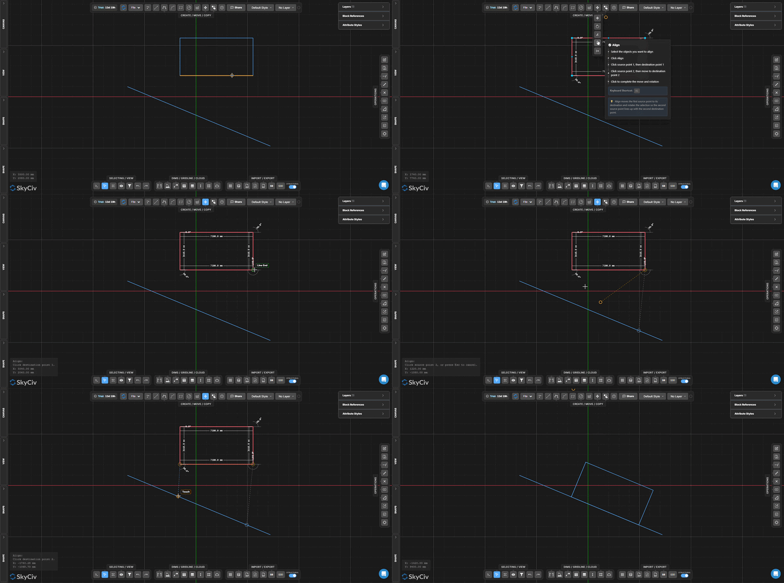
Passo a passo
- 1Selecione os objetos para alinhar.
- 2Clique Alinhar no menu suspenso Mover.
- 3Clique ponto de origem 1 (na seleção), então ponto de destino 1 (na tela).
- 4Clique ponto de origem 2 (na seleção), então vá para ponto de destino 2.
- 5Clique para concluir – a seleção é simultaneamente transladada e girada para que ambos os pares de pontos coincidam.
Comece selecionando a parte da estrutura que você deseja espelhar: Alinhar move o ponto de origem 1 para o ponto de destino 1, em seguida, gira toda a seleção para que o ponto de origem 2 alinha-se com o ponto de destino 2. Use snaps para escolher pontos exatos na geometria existente.
Suprimindo e mudando sua estrutura Repita
Refletir objetos selecionados através de uma linha de espelho definida pelo usuário
MI
A Suprimindo e mudando sua estrutura Repita ferramenta reflete objetos selecionados através de um eixo de espelho definido por dois pontos. Os objetos originais são substituídos por suas contrapartes espelhadas. Para manter os originais, usar Cópia espelhada em vez de.
[__INSERT_IMAGE__]
Passo a passo
- 1Selecione os objetos a serem espelhados.
- 2Clique Suprimindo e mudando sua estrutura Repita (ou pressione MI) no menu suspenso Mover.
- 3Clique para definir o ponto de partida da linha do espelho.
- 4Clique para definir o ponto final da linha do espelho.
- 5A seleção é refletida no eixo definido.
Comece selecionando a parte da estrutura que você deseja espelhar: A linha do espelho pode estar em qualquer ângulo. Ajustar à geometria existente para obter um eixo preciso. Usar Cópia espelhada quando você precisa manter o resultado original e o espelhado.
Suprimindo e mudando sua estrutura Repita
A Suprimindo e mudando sua estrutura Repita grupo da barra de ferramentas cria duplicatas de objetos selecionados – por deslocamento, espelho, variedade, cdot K_a, ou rotação. Selecione os objetos primeiro, em seguida, ative a operação de cópia desejada no menu suspenso Copiar.
Cópia relativa
Copie os objetos selecionados e desloque a cópia por um vetor definido pelo usuário
A Cópia relativa ferramenta duplica objetos selecionados e coloca a cópia em um deslocamento definido escolhendo um ponto base e um destino. O fluxo de trabalho é idêntico ao Movimento Relativo – mas os originais permanecem no lugar.
[__INSERT_IMAGE__]
Passo a passo
- 1Selecione os objetos a serem copiados.
- 2Clique Cópia relativa no menu suspenso Copiar.
- 3Clique em qualquer lugar da tela para definir o ponto base.
- 4Mova o mouse – uma visualização ao vivo da cópia segue o cursor.
- 5Clique para colocar a cópia, ou digite uma distância exata e pressione Encomende Viagra online na Inglaterra.
Comece selecionando a parte da estrutura que você deseja espelhar: Aperte Mudança+Aba para alternar entre cartesiano e Polar modos de entrada. Você pode colocar múltiplas cópias continuando a clicar – hip-delete-não usado Esc sair.
Cópia espelhada
Crie uma duplicata espelhada enquanto mantém os objetos originais
Momento da carga ao vivo
Cópia espelhada cria uma duplicata refletida de objetos selecionados em um eixo definido pelo usuário, deixando os originais no lugar. Use isso em vez de Suprimindo e mudando sua estrutura Repita quando você precisa do original e de seu reflexo.
[__INSERT_IMAGE__]
Passo a passo
- 1Selecione os objetos para cópia espelhada.
- 2Clique Cópia espelhada (ou pressione Momento da carga ao vivo) no menu suspenso Copiar.
- 3Clique para definir o ponto de partida da linha do espelho.
- 4Clique para definir o ponto final da linha do espelho.
- 5Uma cópia espelhada é criada – os originais permanecem inalterados.
Comece selecionando a parte da estrutura que você deseja espelhar: O eixo do espelho pode estar em qualquer ângulo. Snap à geometria existente para definir um eixo preciso. Usar Suprimindo e mudando sua estrutura Repita se você quiser substituir os originais em vez de mantê-los.
Copiar matriz
Distribuir cópias de objetos selecionados em um padrão de matriz linear
RA
A Copiar matriz ferramenta distribui múltiplas cópias de objetos selecionados ao longo de uma direção vetorial. O número de cópias e a extensão total são configurados no Formas painel, tornando-o ideal para elementos estruturais regularmente espaçados, como colunas, treliças, e grupos de parafusos.
[__INSERT_IMAGE__]
Passo a passo
- 1Selecione os objetos para array.
- 2Defina o contagem de cópias e distância do vão no Formas painel.
- 3Clique Copiar matriz (ou pressione RA) no menu suspenso Copiar.
- 4Clique para definir o ponto base da matriz.
- 5Mova o mouse para definir a direção, em seguida, clique para criar as cópias.
Comece selecionando a parte da estrutura que você deseja espelhar: Configure a contagem e a extensão de cópias no arquivo Formas painel antes de ativar a ferramenta. Para matrizes rotacionais (padrões circulares), usar Copiar por Rotação em vez de.
Cópia deslocada
Crie uma cópia paralela de linhas ou polilinhas a uma distância perpendicular especificada
O
A Cópia deslocada ferramenta cria uma duplicata paralela de linhas ou polilinhas selecionadas em uma distância perpendicular especificada. Equivalente ao comando OFFSET do AutoCAD – comumente usado para espessura de parede, marcações de pista, e membros estruturais paralelos.
[__INSERT_IMAGE__]
Passo a passo
- 1Selecione as linhas ou polilinhas a serem deslocadas.
- 2Digite o distância de deslocamento no Formas painel.
- 3Clique Cópia deslocada (ou pressione O) no menu suspenso Copiar.
- 4A cópia offset é criada paralelamente ao original na distância especificada.
Comece selecionando a parte da estrutura que você deseja espelhar: Use um positivo valor a ser deslocado para um lado e um negativo valor para o outro. A direção é relativa à orientação da linha original.
Copiar por Rotação
Crie várias cópias giradas organizadas em torno de um ponto central
A Copiar por Rotação ferramenta cria múltiplas cópias de objetos selecionados em uma circular (polar) padrão em torno de um ponto central. Útil para estruturas radialmente simétricas, como grupos de parafusos em um flange ou membros em uma treliça circular.
[__INSERT_IMAGE__]
Passo a passo
- 1Selecione os objetos a serem copiados por rotação.
- 2Defina o contagem de cópias e ângulo de rotação total no Formas painel.
- 3Clique Copiar por Rotação no menu suspenso Copiar.
- 4Clique para definir o ponto central de rotação.
- 5Mova o mouse para visualizar, em seguida, clique para criar as cópias.
Comece selecionando a parte da estrutura que você deseja espelhar: Para cópias com espaçamento uniforme em torno de um círculo completo, defina o ângulo para 360° e a contagem até o número desejado. Configure ambos os valores em Formas antes de ativar a ferramenta.
