
Column splice connection design to AISC 360 starts with one question: is the joint finished to bear? If the column ends are milled and fit to bear, the axial compression passes straight from the upper column into the lower one, and the splice plates only have to carry the moment, the shear and any tension. The flange plates carry the moment as a tension and compression couple, the web plates carry the shear, and every bolt group, plate and column section on that path is checked above and below the joint.
This page works through one real bolted column splice from start to finish: a W14x90 upper column spliced to a W14x211 lower column, con 1000 kip of compression, 50 Kip di tensione, un carico 150 kip shear and a 100 kip-ft moment, progettato per AISC 360-16 LRFD and the AISC Manual 15th Edition. Each flange has a 1/2 entro 14.5 in flange plate with six 1 in A490 slip-critical bolts on each side of the joint, two bolt lines at an 11.5 in gage by three rows. The web has a pair of 7/8 in web plates, 6 in wide, with four 1 in A490 slip-critical bolts on each side. Every equation is written out with its numbers, in the same order as the AISC calc sheet the Progettazione di connessioni SkyCiv module produces for it.
What is a column splice connection?
A column splice joins two lengths of column end to end. Columns are usually spliced every two or three storeys, a little above floor level, because that is as long as a column can be shipped and erected in one piece. The section often gets lighter going up the building, which is the case here: the heavy W14x211 below carries the floors above it, and the W14x90 above carries less.
In a bolted column splice, flange plates lap across the joint on the outside of both flanges, and a pair of web plates lap across the web. The two columns are different depths, so fillers or shims pack out the gap between the shallower column and the plates. You can check this configuration in the column splice connection calculator. The flange and web plates are checked much like those of a beam splice connection, che per il bolted splice connection calculator covers simpler lap splices.
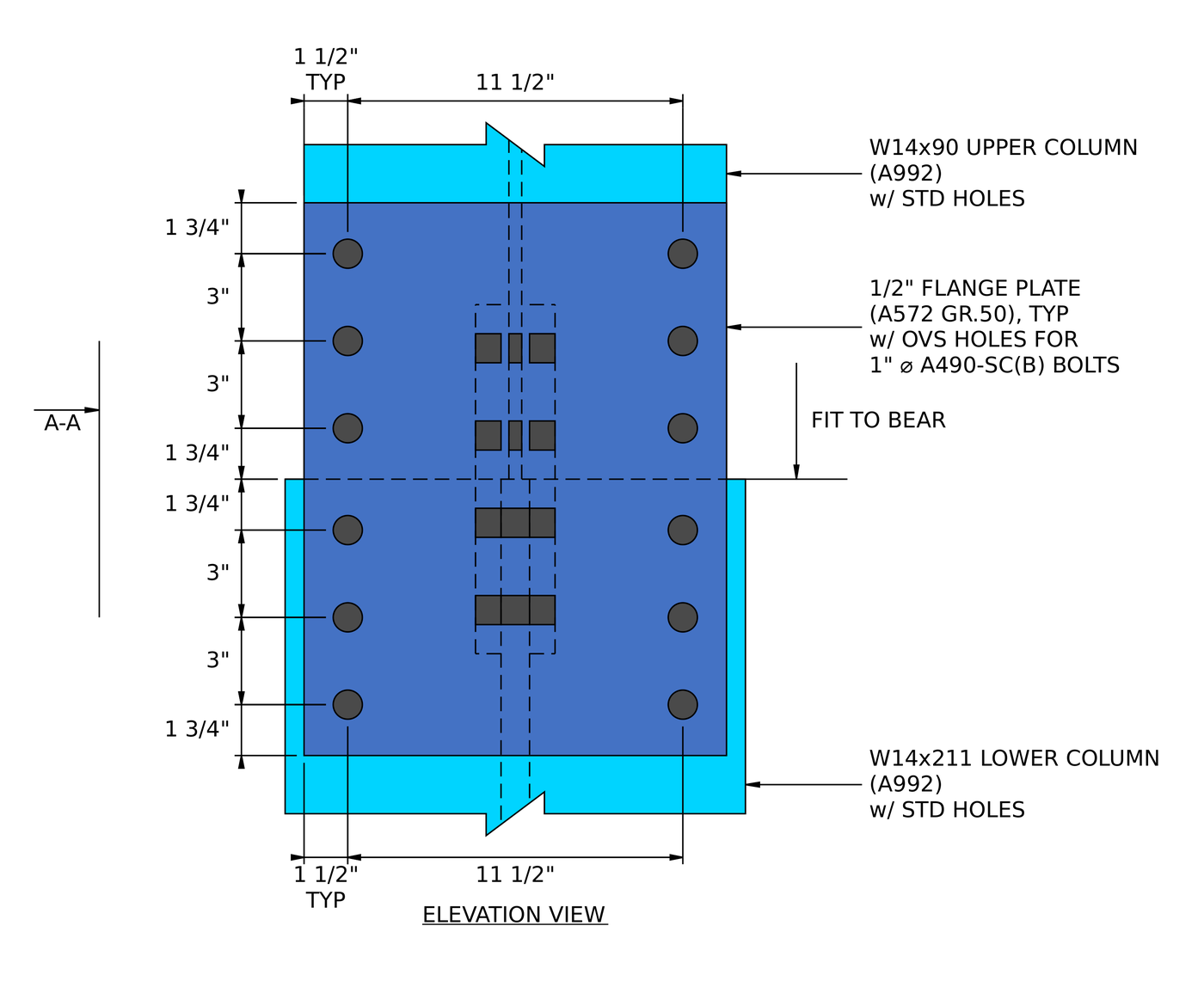
Elevation of the flange splice. La 1/2 in flange plate has two bolt lines at an 11 1/2 in gage, 1 1/2 in in from each plate edge, and three bolt rows on each side of the joint at 3 in spacing, con 1 3/4 in end distances. The column ends are fit to bear.
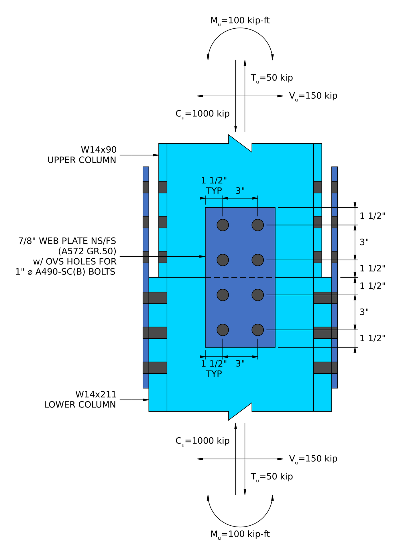
Sezione A-A. La 7/8 in web plates sit on both faces of the web (NS/FS), with two rows of two bolts on each side of the joint at 3 in spacing and 1 1/2 in edge and end distances. Shim plates fill every gap between the columns and the plates.
Column splice connection design: the steps at a glance
First the loads are split: compression goes to bearing, and the moment, tension and shear go to the plates. Then the flange plate splice is checked at the lower column and at the upper column, followed by the web plate splice.
- Check the detailing limits for the flange plate bolts.
- Find the filler factor and check slip of the slip-critical flange bolts.
- Check bolt bearing and tear-out on the flange plate.
- Check bolt bearing and tear-out on the column flange.
- Check block shear of the flange plate for three tear-out patterns.
- Check block shear of the column flange.
- Check tension yielding and rupture of the flange plate.
- Check tension rupture of the column, with shear lag.
- Check flexural rupture of the column at the flange bolt holes.
- Check the flange plate in compression.
- Repeat the flange checks for the upper column.
- Check the detailing limits for the web plate bolts.
- Check slip of the web bolt group under the resultant of shear and axial load.
- Check bolt bearing on the web plates for shear, axial load and their interaction.
- Check bolt bearing on the column web for shear, axial load and their interaction.
- Check block shear of the web plates for shear, axial load and their interaction.
- Check block shear of the column web for axial load.
- Check shear yielding and shear rupture of the web plates.
- Check tension yielding and rupture of the web plates.
- Check tension rupture of the column web, with shear lag.
- Check the web plates in compression.
- Repeat the web checks for the upper column.
Design inputs for this example
The design code is AISC 360-16 LRFD. Section properties are from the AISC Manual.
| Caricare | Simbolo | Valore |
|---|---|---|
| Factored shear | [mathin] V_{u} [mathin] | 150 kip |
| Factored axial tension | [mathin] T_{u} [mathin] | 50 kip |
| Factored axial compression | [mathin] C_{u} [mathin] | 1000 kip |
| Factored strong-axis moment | [mathin] M_{u} [mathin] | 100 kip-ft |
| Column property | Simbolo | Lower column | Upper column |
|---|---|---|---|
| Sezione | W14x211, A992 | L14x90, A992 | |
| ACI-Verifica-Libri-Anteprima | [mathin] d [mathin] | 15.7 pollici | 14 pollici |
| Spessore del nastro | [mathin] t_{w} [mathin] | 0.98 pollici | 0.44 pollici |
| Flange width | [mathin] b_{f} [mathin] | 15.8 pollici | 14.5 pollici |
| Flange thickness | [mathin] t_{f} [mathin] | 1.56 pollici | 0.71 pollici |
| l'Area | [mathin] A [mathin] | 62 in² | 26.5 in² |
| Plastic section modulus | [mathin] Z_{x} [mathin] | 390 in³ | 157 in³ |
| Prodotto / sollecitazione di trazione | [mathin] F_{y},\ F_{u} [mathin] | 50 KSI / 65 KSI | 50 KSI / 65 KSI |
| Flange plate splice | Simbolo | Lower column | Upper column |
|---|---|---|---|
| Flange plate width / spessore | [mathin] b_{fp},\ t_{fp} [mathin] | 14.5 pollici / 0.5 pollici, A572 Gr. 50 | 14.5 pollici / 0.5 pollici, A572 Gr. 50 |
| Plate yield / sollecitazione di trazione | [mathin] F_{yp},\ F_{up} [mathin] | 50 KSI / 65 KSI | 50 KSI / 65 KSI |
| bulloni | 1 in A490-SC, Class B, one slip plane | 1 in A490-SC, Class B, one slip plane | |
| Bolt nominal tensile / sforzo di taglio | [mathin] F_{nt},\ F_{nv} [mathin] | 113 KSI / 68 KSI | 113 KSI / 68 KSI |
| Holes in plate / flangia della colonna | Oversized (OVS) / standard (malattie sessualmente trasmissibili) | Oversized (OVS) / standard (malattie sessualmente trasmissibili) | |
| Bolt lines / gage | [mathin] n_{r},\ g_{a} [mathin] | 2 / 11.5 pollici | 2 / 11.5 pollici |
| Bolt rows / spaziatura | [mathin] n_{c},\ s_{c} [mathin] | 3 / 3 pollici | 3 / 3 pollici |
| Edge distance across the plate / flangia della colonna | [mathin] L_{ev,fp},\ L_{ev,c} [mathin] | 1.5 pollici / 2.125 pollici | 1.5 pollici / 1.5 pollici |
| End distance on plate / flangia della colonna | [mathin] L_{eh,fp},\ L_{eh,c} [mathin] | 1.75 pollici / 1.75 pollici | 1.75 pollici / 1.75 pollici |
| Unbraced length of plate | [mathin] L_{b} [mathin] | 3.5 pollici | 3.5 pollici |
| Web plate splice | Simbolo | Lower column | Upper column |
|---|---|---|---|
| Web plate width / spessore | [mathin] b_{wp},\ t_{wp} [mathin] | 6 pollici / 0.875 in each, A572 Gr. 50 | 6 pollici / 0.875 in each, A572 Gr. 50 |
| bulloni | 1 in A490-SC, Class B, two slip planes | 1 in A490-SC, Class B, two slip planes | |
| Holes in plate / column web | Oversized (OVS) / standard (malattie sessualmente trasmissibili) | Oversized (OVS) / standard (malattie sessualmente trasmissibili) | |
| Bolt rows / row spacing | [mathin] n_{r},\ s_{r} [mathin] | 2 / 3 pollici | 2 / 3 pollici |
| Bolt columns / column spacing | [mathin] n_{c},\ s_{c} [mathin] | 2 / 3 pollici | 2 / 3 pollici |
| Web plate vertical edge distance | [mathin] L_{ev,wp} [mathin] | 1.5 pollici | 1.5 pollici |
| End distance on web plate / column web | [mathin] L_{eh,wp},\ L_{eh,c} [mathin] | 1.5 pollici / 1.5 pollici | 1.5 pollici / 1.5 pollici |
| Web plate length on each side of the joint | [mathin] L_{wp} [mathin] | 6 pollici | 6 pollici |
| Unbraced length of plate | [mathin] L_{b} [mathin] | 3 pollici | 3 pollici |
In a column the bolts are laid out along the member, which is vertical. The report keeps the beam splice naming, quindi il “colonne a bullone” of the flange splice are the three rows of bolts stacked up each column, che per il “orizzontale” edge distance is the end distance to the plate end or the column end.
The edge distances across the flange come from the gage. La 14.5 in plate with an 11.5 in gage leaves [mathin] (14.5 – 11.5)/2 = 1.5\,in [mathin] on each side, and so does the 14.5 in flange of the W14x90. The lower column uses the W14x211 detailing flange width of 15 3/4 pollici, COSÌ [mathin] L_{ev,c} = (15.75 – 11.5)/2 = 2.125\,in [mathin].
How the loads are split in a column splice
The column ends are milled and fit to bear, which is the note on the elevation. AISC 360-16 J1.4 allows compression to pass through a finished bearing joint, so the splice plates do not need to carry it. The bearing strength of the milled surface uses J7, with the bearing area of the smaller column:
[math] C_{u,brg} = \min\left( C_{u},\, \phi\, 1.8\, F_{y}\, A_{brg} \right) = \min\left( (1000\,kip),\, (0.75) \times 1.8 \times (50\,ksi) \times (26.125\,in^{2}) \right) = 1000\,kip [math]
The bearing area of 26.125 in² is the two flanges and the web of the W14x90 from its nominal dimensions, [mathin] 2 \times 14.5 \times 0.71 + (14 – 2 \times 0.71) \times 0.44 = 26.125\,in^{2} [mathin], so it leaves out the fillets that the 26.5 in² tabulated area includes. Tutto 1000 kip of compression goes into bearing, so the compression left for the web plates is zero:
[math] C_{web} = 0\,kip [math]
The moment is turned into a flange force couple using the lever arm of the shallower upper column, [mathin] d – t_{f} = 14 – 0.71 = 13.29\,in [mathin]. The compression flange force is only the moment couple, because no compression is left over from bearing:
[math] C_{flange} = \frac{C_{u} – C_{u,brg} – C_{web}}{2} + \frac{M_{u}}{d_{uc} – t_{f,uc}} = \frac{(1000\,kip) – (1000\,kip) – (0\,kip)}{2} + \frac{(100\,kip\text{-}ft)}{(14\,in) – (0.71\,in)} = 90.293\,kip [math]
Tension cannot pass through bearing, so it is shared between the flanges and the web. The web takes the share of the 50 kip proportioned to the web area over the gross area, [mathin] T_{web} = 9.9423\,kip [mathin], and the flanges take the rest, half each:
[math] T_{flange} = \frac{T_{u} – T_{web}}{2} + \frac{M_{u}}{d_{uc} – t_{f,uc}} = \frac{(50\,kip) – (9.9423\,kip)}{2} + \frac{(100\,kip\text{-}ft)}{(14\,in) – (0.71\,in)} = 110.32\,kip [math]
[math] P_{flange} = \max\left( T_{flange},\, C_{flange} \right) = \max\left( (110.32\,kip),\, (90.293\,kip) \right) = 110.32\,kip [math]
The web plates carry the full shear plus the web share of the tension. Their resultant is used for the web bolt slip check:
[math] P_{web} = 9.9423\,kip, \quad R_{u} = \sqrt{V_{u}^{2} + P_{web}^{2}} = \sqrt{(150\,kip)^{2} + (9.9423\,kip)^{2}} = 150.33\,kip [math]
Bearing makes a large difference here. Without it, each flange plate would have to carry half of the 1000 kip on top of the moment couple, which this 1/2 in plate and six bolts could not do. The fit-to-bear note on the drawing is part of the design, not a fabrication detail.
Parte 1: Flange plate splice at the lower column
Step 1: Detailing limits for the flange plate bolts (AISC 360-16 J3.3, J3.4, J3.5)
The flange bolts must be spaced far enough apart to tighten and close enough together to act as a group, and every bolt needs enough edge distance on both the plate and the column flange.
The plate has oversized holes, so Table J3.5 adds 1/8 in to the Table J3.4 minimum edge distance of 1.25 pollici, dando 1.375 in on the plate. The column flange has standard holes and keeps 1.25 pollici.
| Detailing limit | Limit (pollici) | Effettivo (pollici) | DCR | Risultato |
|---|---|---|---|---|
| Minimum bolt gage | 5.375 | 11.500 | 0.467 | Metà dell'altezza del muro dal fondo della base per il caso del |
| Minimum bolt row spacing | 2.667 | 3.000 | 0.889 | Metà dell'altezza del muro dal fondo della base per il caso del |
| Maximum bolt row spacing | 6.000 | 3.000 | 0.500 | Metà dell'altezza del muro dal fondo della base per il caso del |
| Flange plate minimum edge distance, across | 1.375 | 1.500 | 0.917 | Metà dell'altezza del muro dal fondo della base per il caso del |
| Flange plate minimum end distance | 1.375 | 1.750 | 0.786 | Metà dell'altezza del muro dal fondo della base per il caso del |
| Column flange minimum edge distance, across | 1.250 | 2.125 | 0.588 | Metà dell'altezza del muro dal fondo della base per il caso del |
| Column flange minimum end distance | 1.250 | 1.750 | 0.714 | Metà dell'altezza del muro dal fondo della base per il caso del |
DCR = 1.375 pollici / 1.5 in = 0.917 < 1.0, ok
The edge distance across the flange plate governs. With an 11.5 in gage on a 14.5 nel piatto, each bolt line sits 1.5 in from the plate edge, solo 1/8 in more than the oversized-hole minimum.
Step 2: Slip-critical bolt strength at the flange (AISC 360-16 J3.8, Manual Table 14-3)
The plates have oversized holes, which AISC 360-16 J3.2 allows only in slip-critical joints. The bolt group must resist the flange force by friction, without slipping into bearing. Fillers between the plate and the column reduce slip resistance, so the filler thickness is found first.
Filler thickness and filler factor
The detailing depths are [mathin] d_{det,lc} = 15.75\,in [mathin] for the W14x211 and [mathin] d_{det,uc} = 14\,in [mathin] for the W14x90, the depths rounded to the nearest 1/16 in that the AISC Manual lists for detailing. The flange plates lie flat on the deeper lower column, so on this side the filler is zero (Manual Table 14-3, Cases I-A and I-B):
[math] t_{f} = \left\lceil \frac{\max\left( d_{det,uc} – d_{det,lc},\, 0 \right)}{2} + 0.125\,in \right\rceil_{0.125\,in} \text{ if } d_{det,lc} – d_{det,uc} \lt 0.25\,in, \text{ otherwise } 0 [math]
[math] t_{f} = 0\,in, \quad h_{f} = 1.0 [math]
With no filler, the filler factor [mathin] h_{f} [mathin] è 1.0.
Slip resistance
Dove [mathin] \phi = 0.85 [mathin] for oversized holes, [mathin] \mu = 0.5 [mathin] for Class B faying surfaces, [mathin] D_{u} = 1.13 [mathin], [mathin] T_{b} = 64\,kip [mathin] for a 1 in A490 bolt, [mathin] N_{s} = 1 [mathin] slip plane, e 2 bolt lines by 3 bolt rows:
[math] \phi R_{n} = \phi\, \mu\, D_{u}\, h_{f}\, T_{b}\, N_{s}\, n_{r}\, n_{c} [math]
[math] \phi R_{n} = (0.85) \times (0.5) \times (1.13) \times (1) \times (64\,kip) \times (1) \times (2) \times (3) [math]
[math] \phi R_{n} = 184.42\,kip [math]
DCR = 110.32 kip / 184.42 kip = 0.598 < 1.0, ok
Step 3: Bolt bearing and tear-out on the flange plate (AISC 360-16 J3.10)
Each bolt bears on the side of its hole in the plate. The end bolt can tear out toward the plate end, and the others toward the hole in front of them. In an oversized hole the hole dimension is [mathin] d_{h} = 1.25\,in [mathin]:
[math] l_{c1} = L_{eh,fp} – \frac{d_{h}}{2} = (1.75\,in) – \frac{(1.25\,in)}{2} = 1.125\,in, \quad l_{c2} = s_{c} – d_{h} = (3\,in) – (1.25\,in) = 1.75\,in [math]
Dove [mathin] t_{fp} = 0.5\,in [mathin], [mathin] F_{up} = 65\,ksi [mathin] e [mathin] \phi = 0.75 [mathin]:
[math] \phi R_{n} = \phi \left[ \min\left(1.2\, l_{c1},\, 2.4\, d_{b}\right) t_{fp} F_{up}\, n_{r} + \min\left(1.2\, l_{c2},\, 2.4\, d_{b}\right) t_{fp} F_{up}\, n_{r} \left( n_{c} – 1 \right) \right] [math]
[math] \phi R_{n} = (0.75) \times \left[ \min\left(1.2 \times 1.125\,in,\, 2.4\,in\right)(0.5\,in)(65\,ksi)(2) + \min\left(1.2 \times 1.75\,in,\, 2.4\,in\right)(0.5\,in)(65\,ksi)(2)(3 – 1) \right] [math]
[math] \phi R_{n} = 270.56\,kip [math]
DCR = 110.32 kip / 270.56 kip = 0.408 < 1.0, ok
Step 4: Bolt bearing and tear-out on the column flange (AISC 360-16 J3.10)
The same check on the column flange uses standard holes, [mathin] d_{h} = 1.125\,in [mathin], che per il 1.56 in thick flange of the W14x211:
[math] l_{c1} = L_{eh,c} – \frac{d_{h}}{2} = (1.75\,in) – \frac{(1.125\,in)}{2} = 1.1875\,in, \quad l_{c2} = s_{c} – d_{h} = (3\,in) – (1.125\,in) = 1.875\,in [math]
[math] \phi R_{n} = (0.75) \times \left[ \min\left(1.2 \times 1.1875\,in,\, 2.4\,in\right)(1.56\,in)(65\,ksi)(2) + \min\left(1.2 \times 1.875\,in,\, 2.4\,in\right)(1.56\,in)(65\,ksi)(2)(3 – 1) \right] [math]
[math] \phi R_{n} = 901.19\,kip [math]
DCR = 110.32 kip / 901.19 kip = 0.122 < 1.0, ok
The lower column flange is more than three times the thickness of the plate, so bearing on the column is not a concern on this side.
Step 5: Block shear of the flange plate (AISC 360-16 J4.3)
A block of the flange plate can tear out around the bolts: shear along the bolt lines to the plate end, and tension across the plate. The report checks three patterns and takes the lowest. In each, the hole size for net area is [mathin] d_{h} + 1/16\,in [mathin].
L pattern
One shear plane along a bolt line, and tension across from that line to the far plate edge:
[math] A_{nt} = t_{fp} \left[ (n_{r} – 2)\, s_{r} + g_{a} + L_{ev,fp} – (n_{r} – 0.5)\left( d_{h} + 0.0625\,in \right) \right] = (0.5\,in) \times \left[ 0 + 11.5\,in + 1.5\,in – 1.5(1.3125\,in) \right] = 5.5156\,in^{2} [math]
[math] A_{gv} = t_{fp} \left[ L_{eh,fp} + (n_{c} – 1)\, s_{c} \right] = (0.5\,in) \times \left[ 1.75\,in + 2(3\,in) \right] = 3.875\,in^{2} [math]
[math] A_{nv} = t_{fp} \left[ L_{eh,fp} + (n_{c} – 1)\, s_{c} – (n_{c} – 0.5)\left( d_{h} + 0.0625\,in \right) \right] = (0.5\,in) \times \left[ 7.75\,in – 2.5(1.3125\,in) \right] = 2.2344\,in^{2} [math]
[math] \phi R_{n} = \phi \left( 0.6\, F_{up}\, A_{nv} + U_{bs}\, F_{up}\, A_{nt} \right) \le \phi \left( 0.6\, F_{yp}\, A_{gv} + U_{bs}\, F_{up}\, A_{nt} \right) [math]
[math] \phi R_{n} = (0.75) \left( 0.6 \times 65 \times 2.2344 + 1 \times 65 \times 5.5156 \right) \le (0.75) \left( 0.6 \times 50 \times 3.875 + 1 \times 65 \times 5.5156 \right) = 334.24\,kip [math]
U pattern
Two shear planes along both bolt lines, and tension across the gage between them:
[math] A_{gv} = 2t_{fp} \left[ L_{eh,fp} + (n_{c} – 1)\, s_{c} \right] = 7.75\,in^{2}, \quad A_{nv} = 4.4687\,in^{2} [math]
[math] A_{nt} = t_{fp} \left[ (n_{r} – 2)\, s_{r} + g_{a} – (n_{r} – 1)\left( d_{h} + 0.0625\,in \right) \right] = (0.5\,in) \times \left[ 11.5\,in – 1.3125\,in \right] = 5.0938\,in^{2} [math]
[math] \phi R_{n} = (0.75) \left( 0.6 \times 65 \times 4.4687 + 1 \times 65 \times 5.0938 \right) \le (0.75) \left( 0.6 \times 50 \times 7.75 + 1 \times 65 \times 5.0938 \right) = 379.03\,kip [math]
2L pattern
Two shear planes along both bolt lines, and tension from each line out to its own plate edge:
[math] A_{nt} = 2t_{fp} \left[ L_{ev,fp} – 0.5\left( d_{h} + 0.0625\,in \right) \right] = (1\,in) \times \left[ 1.5\,in – 0.5(1.3125\,in) \right] = 0.84375\,in^{2} [math]
[math] \phi R_{n} = (0.75) \left( 0.6 \times 65 \times 4.4687 + 1 \times 65 \times 0.84375 \right) \le (0.75) \left( 0.6 \times 50 \times 7.75 + 1 \times 65 \times 0.84375 \right) = 171.84\,kip [math]
[math] \phi R_{n} = \min\left( 334.24\,kip,\, 379.03\,kip,\, 171.84\,kip \right) = 171.84\,kip [math]
DCR = 110.32 kip / 171.84 kip = 0.642 < 1.0, ok
The 2L pattern governs. The wide 11.5 in gage puts a lot of tension area between the bolt lines, which helps the L and U patterns, but it leaves only a 1.5 in strip outside each line. After the half hole comes out, the 2L block has less than 0.85 in² of net tension area.
Step 6: Block shear of the column flange (AISC 360-16 J4.3)
The column flange can tear out the same way. Its edges are the flange tips, so the 2L pattern applies: shear along both bolt lines to the column end, and tension from each bolt line out to the flange tip.
[math] A_{nt} = t_{f,lc} \left[ b_{f,lc} – g_{a} – (n_{r} – 1)\left( d_{h} + 0.0625\,in \right) \right] = (1.56\,in) \times \left[ 15.8\,in – 11.5\,in – 1.1875\,in \right] = 4.8555\,in^{2} [math]
[math] A_{gv} = 2t_{f,lc} \left[ L_{eh,c} + (n_{c} – 1)\, s_{c} \right] = 2 \times (1.56\,in) \times \left[ 1.75\,in + 2(3\,in) \right] = 24.18\,in^{2} [math]
[math] A_{nv} = 2t_{f,lc} \left[ L_{eh,c} + (n_{c} – 1)\, s_{c} – (n_{c} – 0.5)\left( d_{h} + 0.0625\,in \right) \right] = 14.918\,in^{2} [math]
[math] \phi R_{n} = (0.75) \left( 0.6 \times 65 \times 14.918 + 1 \times 65 \times 4.8555 \right) \le (0.75) \left( 0.6 \times 50 \times 24.18 + 1 \times 65 \times 4.8555 \right) = 673.04\,kip [math]
DCR = 110.32 kip / 673.04 kip = 0.164 < 1.0, ok
Step 7: Tension yielding and rupture of the flange plate (AISC 360-16 J4.1)
The flange plate carries the full flange force across the joint, so its gross section must not yield and its net section through the two holes must not rupture.
[math] \phi R_{n,ty} = \phi\, F_{yp}\, t_{fp}\, b_{fp} = (0.9) \times (50\,ksi) \times (0.5\,in) \times (14.5\,in) = 326.25\,kip [math]
[math] \phi R_{n,tr} = \phi\, F_{up}\, t_{fp} \left[ b_{fp} – n_{r}\left( d_{h} + 0.0625\,in \right) \right] = (0.75) \times (65\,ksi) \times (0.5\,in) \times \left[ 14.5\,in – 2 \times (1.3125\,in) \right] = 289.45\,kip [math]
[math] \phi R_{n} = \min\left( 326.25\,kip,\, 289.45\,kip \right) = 289.45\,kip [math]
DCR = 110.32 kip / 289.45 kip = 0.381 < 1.0, ok
Step 8: Tension rupture of the column, with shear lag (AISC 360-16 D3, J4.1)
The flange force also has to get into the column. Only the flange is bolted, so the report treats half the column as a tee and applies shear lag from Table D3.1, Astuccio 2. The tee’s centroid is [mathin] \bar{y} = 1.5842\,in [mathin] from the outside of the flange, and the connection length is [mathin] l = (n_{c} – 1)\, s_{c} = 6\,in [mathin]:
[math] U = 1 – \frac{\bar{y}}{l} = 1 – \frac{1.5842\,in}{6\,in} = 0.73606 [math]
[math] \phi R_{n} = \phi\, F_{u}\, U \left[ 0.5\, A_{lc} – n_{r}\left( d_{h} + 0.0625\,in \right) t_{f,lc} \right] = (0.75) \times (65\,ksi) \times (0.73606) \times \left[ 0.5 \times (62\,in^{2}) – 2 \times (1.1875\,in) \times (1.56\,in) \right] [math]
[math] \phi R_{n} = 979.43\,kip [math]
DCR = 110.32 kip / 979.43 kip = 0.113 < 1.0, ok
Three bolt rows give a 6 in connection length, so the shear lag factor drops to about 0.74. A short connection on a deep tee loses more of its net area to shear lag than a long one.
Step 9: Flexural rupture of the column at the bolt holes (AISC 360-16 F13.1)
The bolt holes in the tension flange can reduce the column’s flexural strength. F13.1 compares the rupture strength of the net flange with the yield strength of the gross flange to decide whether they do.
[math] A_{fg} = b_{f,lc}\, t_{f,lc} = (15.8\,in) \times (1.56\,in) = 24.648\,in^{2} [math]
[math] A_{fn} = A_{fg} – n_{r}\left( d_{h} + 0.0625\,in \right) t_{f,lc} = (24.648\,in^{2}) – 2 \times (1.1875\,in) \times (1.56\,in) = 20.943\,in^{2} [math]
The ratio [mathin] F_{y}/F_{u} = 50/65 = 0.76923 [mathin] is not more than 0.8, COSÌ [mathin] Y_{t} = 1.0 [mathin]:
[math] F_{u}\, A_{fn} = (65\,ksi) \times (20.943\,in^{2}) = 1361.3\,kip \ge Y_{t}\, F_{y}\, A_{fg} = (1) \times (50\,ksi) \times (24.648\,in^{2}) = 1232.4\,kip [math]
Perché [mathin] F_{u} A_{fn} [mathin] non è inferiore a [mathin] Y_{t} F_{y} A_{fg} [mathin], the limit state of tensile rupture does not apply, and the holes do not limit flexure. The column keeps its plastic moment:
[math] M_{n} = F_{y}\, Z_{x} = (50\,ksi) \times (390\,in^{3}) = 1625\,kip\text{-}ft [math]
That moment is converted to a flange force over the column’s own lever arm, so it can be compared with the flange force:
[math] \phi R_{n} = \frac{\phi\, M_{n}}{d_{lc} – t_{f,lc}} = \frac{(0.9) \times (1625\,kip\text{-}ft)}{(15.7\,in) – (1.56\,in)} = 1241.2\,kip [math]
DCR = 110.32 kip / 1241.2 kip = 0.089 < 1.0, ok
Step 10: Compression strength of the flange plate (AISC 360-16 J4.4, E3)
On the compression side of the moment, the flange plate spans between the nearest bolts above and below the joint as a short column. Its compression demand is the 90.293 kip moment couple from the load split, because the axial compression goes through bearing.
Con [mathin] K = 1.2 [mathin], [mathin] L_{b} = 3.5\,in [mathin] e [mathin] r = t_{fp}/\sqrt{12} [mathin]:
[math] \frac{K L}{r} = \frac{(1.2) \times (3.5\,in)}{(0.5\,in) / \sqrt{12}} = 29.098 \gt 25 [math]
KL/r is above 25, so J4.4 sends the plate to Chapter E. The slenderness is below [mathin] 4.71\sqrt{E/F_{y}} = 113.43 [mathin], so Eq. E3-2 applies:
[math] F_{e} = \frac{\pi^{2} E}{\left( KL/r \right)^{2}} = \frac{\pi^{2} \times (29000\,ksi)}{(29.098)^{2}} = 338.03\,ksi [math]
[math] F_{cr} = 0.658^{F_{yp}/F_{e}} F_{yp} = 0.658^{(50/338.03)} \times (50\,ksi) = 46.998\,ksi [math]
[math] \phi R_{n} = \phi\, F_{cr}\, t_{fp}\, b_{fp} = (0.9) \times (46.998\,ksi) \times (0.5\,in) \times (14.5\,in) = 306.66\,kip [math]
DCR = 90.293 kip / 306.66 kip = 0.294 < 1.0, ok
Buckling takes only about 6% off the yield stress at this slenderness. A thinner plate or a longer unbraced length would cost more, because r drops with the plate thickness.
Step 11: Flange plate splice at the upper column
The same flange plate and bolt layout are used on the W14x90, so the plate checks (bearing on the plate, block shear of the plate, plate tension and plate compression) give the same results as at the lower column. Three things change: the column flange is thinner at 0.71 pollici, the minimum gage drops to 4.875 pollici, and there is now a filler.
Filler on the upper column
The W14x90 is 1.75 in shallower than the W14x211, so the flange plates stand off its flanges and need a filler on each side. The report sizes it with Manual Table 14-3, Cases I-A and I-C:
[math] t_{f} = \left\lfloor \frac{d_{det,lc} – d_{det,uc}}{2} – 0.125\,in \right\rfloor_{0.125\,in} \text{ if } d_{det,lc} – d_{det,uc} \gt 0.625\,in, \text{ otherwise } 0 [math]
[math] t_{f} = 0.625\,in [math]
Any filler thicker than 1/8 in drops the filler factor to 0.85, which takes 15% off the slip resistance:
[math] h_{f} = 1.0 \text{ if } t_{f} \le 0.125\,in, \text{ otherwise } 0.85 \quad \Rightarrow \quad h_{f} = 0.85 [math]
[math] \phi R_{n} = (0.85) \times (0.5) \times (1.13) \times (0.85) \times (64\,kip) \times (1) \times (2) \times (3) = 156.75\,kip [math]
DCR = 110.32 kip / 156.75 kip = 0.704 < 1.0, ok
This is the highest flange strength check. The same six bolts have a DCR of 0.598 at the lower column and 0.704 at the upper column, and the only difference is the filler factor.
Other checks at the upper column
| Dai un'occhiata | Key values | Capacità | DCR |
|---|---|---|---|
| Detailing limits | Minimum gage 4.875 pollici (0.424), column flange edge distance 1.5 pollici (0.833) | 1.375 nel limite, 1.5 in actual | 0.917 |
| Bearing on column flange | [mathin] t_{f,uc} = 0.71\,in,\ l_{c1} = 1.1875\,in,\ l_{c2} = 1.875\,in [mathin] | 410.16 kip | 0.269 |
| Block shear of column flange | [mathin] A_{nt} = 1.2869,\ A_{gv} = 11.005,\ A_{nv} = 6.7894\,in^{2} [mathin] | 261.32 kip | 0.422 |
| Column tension rupture | [mathin] \bar{y} = 1.1356\,in,\ U = 0.81081,\ A = 26.5\,in^{2} [mathin] | 457.08 kip | 0.241 |
| Column flexural rupture | [mathin] F_{u}A_{fn} = 559.57 \ge F_{y}A_{fg} = 514.75\,kip,\ M_{n} = 654.17\,kip\text{-}ft [mathin] | 531.60 kip | 0.208 |
The W14x90 flange is the same 14.5 in width as the plate, so its edge distance is also 1.5 pollici. The column flange has standard holes and a 1.25 in minimum, so its ratio is 0.833. The flange plate edge distance still governs the detailing at 0.917.
Block shear of the column flange is the highest column check on this side at 0.422. The 2L tension strip on the W14x90 is only 1.5 in wide on each side and 0.71 di spessore.
Parte 2: Web plate splice at the lower column
Step 12: Detailing limits for the web plate bolts (AISC 360-16 J3.3, J3.4, J3.5)
The web bolt layout has to meet the same spacing and edge distance rules as the flange, and the web plates have to be deep enough to meet the minimum connection depth but still fit between the column flanges.
| Detailing limit | Limit (pollici) | Effettivo (pollici) | DCR | Risultato |
|---|---|---|---|---|
| Minimum bolt row spacing | 2.667 | 3.000 | 0.889 | Metà dell'altezza del muro dal fondo della base per il caso del |
| Maximum bolt row spacing | 6.000 | 3.000 | 0.500 | Metà dell'altezza del muro dal fondo della base per il caso del |
| Minimum bolt column spacing | 2.667 | 3.000 | 0.889 | Metà dell'altezza del muro dal fondo della base per il caso del |
| Maximum bolt column spacing | 6.000 | 3.000 | 0.500 | Metà dell'altezza del muro dal fondo della base per il caso del |
| Web plate minimum vertical edge distance | 1.375 | 1.500 | 0.917 | Metà dell'altezza del muro dal fondo della base per il caso del |
| Web plate minimum horizontal edge distance | 1.375 | 1.500 | 0.917 | Metà dell'altezza del muro dal fondo della base per il caso del |
| Minimum connection depth | 5.000 | 6.000 | 0.833 | Metà dell'altezza del muro dal fondo della base per il caso del |
| Maximum connection depth | 10.000 | 6.000 | 0.600 | Metà dell'altezza del muro dal fondo della base per il caso del |
DCR = 1.375 pollici / 1.5 in = 0.917 < 1.0, ok
Both web plate edge distances are 1.5 in against the oversized-hole minimum of 1.375 pollici. La 6 in plate is exactly 1.5 + 3 + 1.5 pollici, so there is no spare width.
Step 13: Slip-critical bolt strength at the web (AISC 360-16 J3.8)
The web bolts carry the shear and the web tension together, so the slip check uses their resultant, 150.33 kip. The bolts are slip-critical because the web plates have oversized holes.
The lower column web is the thicker one, so there is no filler on this side. Using the detailing web thicknesses, 7/16 in for the W14x90 and 1 in for the W14x211:
[math] t_{f} = \max\left( \frac{tw_{det,uc} – tw_{det,lc}}{2},\, 0 \right) = \max\left( \frac{(0.4375\,in) – (1\,in)}{2},\, 0 \right) = 0\,in, \quad h_{f} = 1 [math]
Dove [mathin] \phi = 0.85 [mathin], [mathin] \mu = 0.5 [mathin], [mathin] D_{u} = 1.13 [mathin], [mathin] T_{b} = 64\,kip [mathin], e [mathin] N_{s} = 2 [mathin] slip planes because there is a web plate on each face of the web:
[math] \phi R_{n} = \phi\, \mu\, D_{u}\, h_{f}\, T_{b}\, N_{s}\, n_{r}\, n_{c} = (0.85) \times (0.5) \times (1.13) \times (1) \times (64\,kip) \times (2) \times (2) \times (2) = 245.89\,kip [math]
DCR = 150.33 kip / 245.89 kip = 0.611 < 1.0, ok
Step 14: Bolt bearing on the web plates (AISC 360-16 J3.10)
The web plate holes are loaded in two directions at once: across the column by the shear, and along the column by the web tension. Bearing and tear-out are checked separately in each direction and then combined. Both plates work together, so the thickness is [mathin] 2t_{wp} = 1.75\,in [mathin], and the bolt group coefficient is [mathin] C = 4 [mathin] because the load is concentric.
Shear direction
[math] l_{c1} = L_{ev,wp} – \frac{d_{h}}{2} = (1.5\,in) – \frac{(1.25\,in)}{2} = 0.875\,in, \quad l_{c2} = s_{r} – d_{h} = (3\,in) – (1.25\,in) = 1.75\,in [math]
[math] \phi R_{n} = \phi \left[ \min\left(1.2\, l_{c1},\, 2.4\, d_{b}\right) 2t_{wp} F_{up} + \min\left(1.2\, l_{c2},\, 2.4\, d_{b}\right) 2t_{wp} F_{up} \left( n_{r} – 1 \right) \right] \frac{C}{n_{r}} [math]
[math] \phi R_{n} = (0.75) \times \left[ \min\left(1.05\,in,\, 2.4\,in\right)(1.75\,in)(65\,ksi) + \min\left(2.1\,in,\, 2.4\,in\right)(1.75\,in)(65\,ksi)(2 – 1) \right] \times \frac{4}{2} = 537.47\,kip [math]
DCR = 150 kip / 537.47 kip = 0.279 < 1.0, ok
Axial direction
The end distance on the web plate is also 1.5 pollici, so the clear distances and the strength are the same as in the shear direction:
[math] l_{c1} = L_{eh,wp} – \frac{d_{h}}{2} = (1.5\,in) – \frac{(1.25\,in)}{2} = 0.875\,in, \quad l_{c2} = s_{c} – d_{h} = 1.75\,in, \quad \phi R_{n} = 537.47\,kip [math]
DCR = 9.9423 kip / 537.47 kip = 0.018 < 1.0, ok
Interaction
[math] \left( \frac{V_{u}}{\phi R_{n,v}} \right)^{2} + \left( \frac{P_{web}}{\phi R_{n,a}} \right)^{2} = \left( \frac{150}{537.47} \right)^{2} + \left( \frac{9.9423}{537.47} \right)^{2} = 0.078231 [math]
DCR = 0.078 < 1.0, ok
Step 15: Bolt bearing on the column web (AISC 360-16 J3.10)
The column web has standard holes, [mathin] d_{h} = 1.125\,in [mathin], ed è 0.98 in thick on the W14x211.
Shear direction
Across the column there is web on both sides of the bolts, so every bolt uses the clear distance between holes, [mathin] l_{c2} = 3 – 1.125 = 1.875\,in [mathin]:
[math] \phi R_{n} = \phi \min\left(1.2\, l_{c2},\, 2.4\, d_{b}\right) t_{w,lc}\, F_{u,lc}\, C = (0.75) \times \min\left(2.25\,in,\, 2.4\,in\right) \times (0.98\,in) \times (65\,ksi) \times (4) = 429.98\,kip [math]
DCR = 150 kip / 429.98 kip = 0.349 < 1.0, ok
Axial direction
Along the column, the bolt row nearest the column end tears out toward it, con [mathin] l_{c1} = L_{eh,c} – d_{h}/2 = 1.5 – 0.5625 = 0.9375\,in [mathin]:
[math] \phi R_{n} = (0.75) \times \left[ \min\left(1.125\,in,\, 2.4\,in\right)(0.98\,in)(65\,ksi) + \min\left(2.25\,in,\, 2.4\,in\right)(0.98\,in)(65\,ksi)(2 – 1) \right] \times \frac{4}{2} = 322.48\,kip [math]
DCR = 9.9423 kip / 322.48 kip = 0.031 < 1.0, ok
Interaction
[math] \left( \frac{150}{429.98} \right)^{2} + \left( \frac{9.9423}{322.48} \right)^{2} = 0.12265 [math]
DCR = 0.123 < 1.0, ok
Step 16: Block shear of the web plates (AISC 360-16 J4.3)
A block of the web plates can tear out under the shear or under the axial force. Each direction has its own tear-out pattern, and the two ratios are combined the same way as for bearing.
Shear load
The block shears along the outer bolt row to the plate edge and tears in tension across the bolt columns to the plate end:
[math] A_{nt} = 2t_{wp} \left[ (n_{c} – 1)\, s_{c} + L_{eh,wp} – (n_{c} – 0.5)\left( d_{h} + 0.0625\,in \right) \right] = (1.75\,in) \times \left[ 3\,in + 1.5\,in – 1.5(1.3125\,in) \right] = 4.4297\,in^{2} [math]
[math] A_{gv} = 2t_{wp} \left[ L_{ev,wp} + (n_{r} – 1)\, s_{r} \right] = (1.75\,in) \times \left[ 1.5\,in + 3\,in \right] = 7.875\,in^{2} [math]
[math] A_{nv} = 2t_{wp} \left[ b_{wp} – L_{ev,wp} – (n_{r} – 0.5)\left( d_{h} + 0.0625\,in \right) \right] = (1.75\,in) \times \left[ 6\,in – 1.5\,in – 1.5(1.3125\,in) \right] = 4.4297\,in^{2} [math]
With two bolt columns the tension stress across the block is not uniform, COSÌ [mathin] U_{bs} = 0.5 [mathin]:
[math] \phi R_{n} = (0.75) \left( 0.6 \times 65 \times 4.4297 + 0.5 \times 65 \times 4.4297 \right) \le (0.75) \left( 0.6 \times 50 \times 7.875 + 0.5 \times 65 \times 4.4297 \right) = 237.54\,kip [math]
DCR = 150 kip / 237.54 kip = 0.631 < 1.0, ok
Carico assiale
In the L pattern, the block tears in tension across the bolt rows and out the plate edge, and shears along one bolt row to the plate end:
[math] A_{nt} = 4.4297\,in^{2}, \quad A_{gv} = 2t_{wp} \left[ L_{eh,wp} + (n_{c} – 1)\, s_{c} \right] = 7.875\,in^{2}, \quad A_{nv} = 2t_{wp} \left[ L_{wp} – L_{eh,c} – (n_{c} – 0.5)\left( d_{h} + 0.0625\,in \right) \right] = 4.4297\,in^{2} [math]
[math] \phi R_{n,L} = (0.75) \left( 0.6 \times 65 \times 4.4297 + 1 \times 65 \times 4.4297 \right) \le (0.75) \left( 0.6 \times 50 \times 7.875 + 1 \times 65 \times 4.4297 \right) = 345.52\,kip [math]
In the U (or C) modello, the block between the two bolt rows pulls out, shearing along both rows:
[math] A_{nt} = 2t_{wp} \left[ (n_{r} – 1)\, s_{r} – (n_{r} – 1)\left( d_{h} + 0.0625\,in \right) \right] = (1.75\,in) \times \left[ 3\,in – 1.3125\,in \right] = 2.9531\,in^{2}, \quad A_{gv} = 15.75\,in^{2}, \quad A_{nv} = 8.8594\,in^{2} [math]
[math] \phi R_{n,U} = (0.75) \left( 0.6 \times 65 \times 8.8594 + 1 \times 65 \times 2.9531 \right) \le (0.75) \left( 0.6 \times 50 \times 15.75 + 1 \times 65 \times 2.9531 \right) = 403.1\,kip [math]
[math] \phi R_{n} = \min\left( 345.52\,kip,\, 403.1\,kip \right) = 345.52\,kip [math]
DCR = 9.9423 kip / 345.52 kip = 0.029 < 1.0, ok
Interaction
[math] \left( \frac{150}{237.54} \right)^{2} + \left( \frac{9.9423}{345.52} \right)^{2} = 0.39958 [math]
DCR = 0.400 < 1.0, ok
Almost all of the 0.400 comes from the shear term. The axial term adds about 0.001.
Step 17: Block shear of the column web (AISC 360-16 J4.3)
Under axial tension, a block of the column web around the bolts can pull out of the column end: tension between the two bolt rows, and shear along both rows to the end of the column. This is the C pattern.
[math] A_{nt} = t_{w,lc} \left[ (n_{r} – 1)\, s_{r} – (n_{r} – 1)\left( d_{h} + 0.0625\,in \right) \right] = (0.98\,in) \times \left[ 3\,in – 1.1875\,in \right] = 1.7762\,in^{2} [math]
[math] A_{gv} = 2t_{w,lc} \left[ L_{eh,c} + (n_{c} – 1)\, s_{c} \right] = 2 \times (0.98\,in) \times \left[ 1.5\,in + 3\,in \right] = 8.82\,in^{2} [math]
[math] A_{nv} = 2t_{w,lc} \left[ (n_{c} – 1)\, s_{c} + L_{eh,c} – (n_{c} – 0.5)\left( d_{h} + 0.0625\,in \right) \right] = 5.3288\,in^{2} [math]
[math] \phi R_{n} = (0.75) \left( 0.6 \times 65 \times 5.3288 + 1 \times 65 \times 1.7762 \right) \le (0.75) \left( 0.6 \times 50 \times 8.82 + 1 \times 65 \times 1.7762 \right) = 242.46\,kip [math]
DCR = 9.9423 kip / 242.46 kip = 0.041 < 1.0, ok
Step 18: Shear yielding and shear rupture of the web plates (AISC 360-16 J4.2)
The two web plates carry the full 150 kip shear across the splice. Their gross section must not yield in shear, and their net section through the bolt holes must not rupture.
Shear yielding (Eq. J4-3)
[math] A_{gv} = b_{wp} \times 2t_{wp} = (6\,in) \times (1.75\,in) = 10.5\,in^{2} [math]
[math] \phi R_{n,sy} = \phi\, 0.6\, F_{yp}\, A_{gv} = (1) \times 0.6 \times (50\,ksi) \times (10.5\,in^{2}) = 315\,kip [math]
Shear rupture (Eq. J4-4)
[math] A_{nv} = 2t_{wp} \left[ b_{wp} – n_{r}\left( d_{h} + 0.0625\,in \right) \right] = (1.75\,in) \times \left[ 6\,in – 2 \times (1.3125\,in) \right] = 5.9062\,in^{2} [math]
[math] \phi R_{n,sr} = \phi\, 0.6\, F_{up}\, A_{nv} = (0.75) \times 0.6 \times (65\,ksi) \times (5.9062\,in^{2}) = 172.76\,kip [math]
[math] \phi R_{n} = \min\left( 315\,kip,\, 172.76\,kip \right) = 172.76\,kip [math]
DCR = 150 kip / 172.76 kip = 0.868 < 1.0, ok
This is the highest strength check in the whole column splice. Two oversized holes take 2.625 in out of a 6 nel piatto, più di 40% of its width, so net section rupture is far below shear yielding. A deeper web plate with a third bolt row, or thicker plates, would add net area directly.
Step 19: Tension yielding and rupture of the web plates (AISC 360-16 J4.1)
Under the tension case, the web plates carry the 9.9423 kip web force across the joint as a tension member.
[math] \phi R_{n,ty} = \phi\, F_{yp}\, 2t_{wp}\, b_{wp} = (0.9) \times (50\,ksi) \times (1.75\,in) \times (6\,in) = 472.5\,kip [math]
[math] \phi R_{n,tr} = \phi\, F_{up}\, 2t_{wp} \left[ b_{wp} – n_{r}\left( d_{h} + 0.0625\,in \right) \right] = (0.75) \times (65\,ksi) \times (1.75\,in) \times \left[ 6\,in – 2 \times (1.3125\,in) \right] = 287.93\,kip [math]
DCR = 9.9423 kip / 287.93 kip = 0.035 < 1.0, ok
Step 20: Tension rupture of the column web, with shear lag (AISC 360-16 D3, J4.1)
The web tension also has to get into the column. Only the web is bolted, so the flanges lag behind in picking up stress, and the whole column section is checked with a shear lag factor from Table D3.1, Astuccio 2. The report uses [mathin] \bar{x} = 3.2088\,in [mathin] for the W14x211 and a shear lag factor of [mathin] U = 0.175 [mathin]:
[math] \phi R_{n} = \phi\, F_{u,lc}\, U \left[ A_{lc} – n_{r}\left( d_{h} + 0.0625\,in \right) t_{w,lc} \right] = (0.75) \times (65\,ksi) \times (0.175) \times \left[ 62\,in^{2} – 2 \times (1.1875\,in) \times (0.98\,in) \right] = 509.08\,kip [math]
DCR = 9.9423 kip / 509.08 kip = 0.020 < 1.0, ok
Qui [mathin] \bar{x} [mathin] is larger than the 3 in connection length, COSÌ [mathin] 1 – \bar{x}/l [mathin] would be negative, and the report uses a low U instead. The DCR is still only 0.020.
Step 21: Compression strength of the web plates (AISC 360-16 J4.4)
Under compression the web plates would act as short columns across the joint. Each plate can buckle on its own, so the radius of gyration is that of one 7/8 nel piatto. Con [mathin] K = 1.2 [mathin] e [mathin] L_{b} = 3\,in [mathin]:
[math] \frac{K L}{r} = \frac{(1.2) \times (3\,in)}{(0.875\,in) / \sqrt{12}} = 14.252 \le 25 [math]
KL/r is not more than 25, so Eq. J4-6 applies, and the plates reach full yield without buckling:
[math] \phi R_{n} = \phi\, F_{yp}\, 2t_{wp}\, b_{wp} = (0.9) \times (50\,ksi) \times (1.75\,in) \times (6\,in) = 472.5\,kip [math]
DCR = 0 kip / 472.5 kip = 0.000 < 1.0, ok
The demand is zero because all of the compression goes through bearing at the milled ends. The check still matters if the joint is not finished to bear, because then the plates would carry the compression.
Step 22: Web plate splice at the upper column
The web plates and bolt layout are the same on the W14x90, so the plate checks (bearing on the plates, block shear of the plates, plate shear, tensione e compressione) give the same results as at the lower column. The column web checks change because the W14x90 web is only 0.44 di spessore.
The thin web also needs a filler. With detailing web thicknesses of 1 in and 7/16 pollici:
[math] t_{f} = \max\left( \frac{tw_{det,lc} – tw_{det,uc}}{2},\, 0 \right) = \max\left( \frac{(1\,in) – (0.4375\,in)}{2},\, 0 \right) = 0.28125\,in [math]
The filler is thicker than 1/8 pollici, COSÌ [mathin] h_{f} = 0.85 [mathin]:
[math] \phi R_{n} = (0.85) \times (0.5) \times (1.13) \times (0.85) \times (64\,kip) \times (2) \times (2) \times (2) = 209\,kip [math]
DCR = 150.33 kip / 209 kip = 0.719 < 1.0, ok
| Dai un'occhiata | Key values | Capacità | DCR |
|---|---|---|---|
| Bearing on column web, cesoia | [mathin] t_{w,uc} = 0.44\,in [mathin] | 193.05 kip | 0.777 |
| Bearing on column web, assiale | [mathin] t_{w,uc} = 0.44\,in [mathin] | 144.79 kip | 0.069 |
| Bearing on column web, interaction | 0.608 | ||
| Block shear of column web | [mathin] A_{nt} = 0.7975,\ A_{gv} = 3.96,\ A_{nv} = 2.3925\,in^{2} [mathin] | 108.86 kip | 0.091 |
| Column web tension rupture | [mathin] \bar{x} = 2.8803\,in,\ U = 0.175,\ A = 26.5\,in^{2} [mathin] | 217.16 kip | 0.046 |
Bearing on the thin W14x90 web is the highest column web check, a 0.777 in shear. Its web is less than half as thick as the W14x211’s, and bearing strength is proportional to the thickness.
Summary of design checks
Flange plate splice
| Design check | Richiesta | Lower capacity | Lower DCR | Upper capacity | Upper DCR | Risultato |
|---|---|---|---|---|---|---|
| Detailing limits | 1.375 pollici / 1.5 pollici | 0.917 | 1.375 pollici / 1.5 pollici | 0.917 | Metà dell'altezza del muro dal fondo della base per il caso del | |
| Slip of flange bolts | 110.32 kip | 184.416 kip | 0.598 | 156.754 kip | 0.704 | Metà dell'altezza del muro dal fondo della base per il caso del |
| Bearing on flange plate | 110.32 kip | 270.563 kip | 0.408 | 270.563 kip | 0.408 | Metà dell'altezza del muro dal fondo della base per il caso del |
| Bearing on column flange | 110.32 kip | 901.193 kip | 0.122 | 410.158 kip | 0.269 | Metà dell'altezza del muro dal fondo della base per il caso del |
| Block shear of flange plate | 110.32 kip | 171.844 kip | 0.642 | 171.844 kip | 0.642 | Metà dell'altezza del muro dal fondo della base per il caso del |
| Block shear of column flange | 110.32 kip | 673.043 kip | 0.164 | 261.324 kip | 0.422 | Metà dell'altezza del muro dal fondo della base per il caso del |
| Flange plate tension | 110.32 kip | 289.453 kip | 0.381 | 289.453 kip | 0.381 | Metà dell'altezza del muro dal fondo della base per il caso del |
| Column tension rupture | 110.32 kip | 979.431 kip | 0.113 | 457.083 kip | 0.241 | Metà dell'altezza del muro dal fondo della base per il caso del |
| Flexural rupture at holes | 110.32 kip | 1241.160 kip | 0.089 | 531.603 kip | 0.208 | Metà dell'altezza del muro dal fondo della base per il caso del |
| Flange plate compression | 90.293 kip | 306.664 kip | 0.294 | 306.664 kip | 0.294 | Metà dell'altezza del muro dal fondo della base per il caso del |
Web plate splice
| Design check | Richiesta | Lower capacity | Lower DCR | Upper capacity | Upper DCR | Risultato |
|---|---|---|---|---|---|---|
| Detailing limits | 1.375 pollici / 1.5 pollici | 0.917 | 1.375 pollici / 1.5 pollici | 0.917 | Metà dell'altezza del muro dal fondo della base per il caso del | |
| Slip of web bolt group | 150.33 kip | 245.888 kip | 0.611 | 209.005 kip | 0.719 | Metà dell'altezza del muro dal fondo della base per il caso del |
| Bearing on web plates, cesoia | 150 kip | 537.469 kip | 0.279 | 537.469 kip | 0.279 | Metà dell'altezza del muro dal fondo della base per il caso del |
| Bearing on web plates, assiale | 9.942 kip | 537.469 kip | 0.018 | 537.469 kip | 0.018 | Metà dell'altezza del muro dal fondo della base per il caso del |
| Bearing on web plates, interaction | 0.078 | 0.078 | Metà dell'altezza del muro dal fondo della base per il caso del | |||
| Bearing on column web, cesoia | 150 kip | 429.975 kip | 0.349 | 193.050 kip | 0.777 | Metà dell'altezza del muro dal fondo della base per il caso del |
| Bearing on column web, assiale | 9.942 kip | 322.481 kip | 0.031 | 144.787 kip | 0.069 | Metà dell'altezza del muro dal fondo della base per il caso del |
| Bearing on column web, interaction | 0.123 | 0.608 | Metà dell'altezza del muro dal fondo della base per il caso del | |||
| Block shear of web plates, cesoia | 150 kip | 237.542 kip | 0.631 | 237.542 kip | 0.631 | Metà dell'altezza del muro dal fondo della base per il caso del |
| Block shear of web plates, assiale | 9.942 kip | 345.516 kip | 0.029 | 345.516 kip | 0.029 | Metà dell'altezza del muro dal fondo della base per il caso del |
| Block shear of web plates, interaction | 0.400 | 0.400 | Metà dell'altezza del muro dal fondo della base per il caso del | |||
| Block shear of column web | 9.942 kip | 242.458 kip | 0.041 | 108.859 kip | 0.091 | Metà dell'altezza del muro dal fondo della base per il caso del |
| Web plate shear | 150 kip | 172.758 kip | 0.868 | 172.758 kip | 0.868 | Metà dell'altezza del muro dal fondo della base per il caso del |
| Web plate tension | 9.942 kip | 287.930 kip | 0.035 | 287.930 kip | 0.035 | Metà dell'altezza del muro dal fondo della base per il caso del |
| Column web tension rupture | 9.942 kip | 509.081 kip | 0.020 | 217.163 kip | 0.046 | Metà dell'altezza del muro dal fondo della base per il caso del |
| Web plate compression | 0 kip | 472.500 kip | 0.000 | 472.500 kip | 0.000 | Metà dell'altezza del muro dal fondo della base per il caso del |
The column splice passes every check. The highest ratio, 0.917, is detailing: every plate edge distance is 1.5 in against the 1.375 in oversized-hole minimum, which means the plates are close to the code minimum, not overstressed. Of the strength checks, shear rupture of the web plates governs at 0.868 on both sides. Next come bearing on the thin W14x90 web at 0.777, slip of the upper web bolts at 0.719 and slip of the upper flange bolts at 0.704, the last two with the 0.85 filler factor.
What to change if a check fails
- Web plate shear rupture or block shear: make the web plates deeper and add a bolt row, or use thicker plates. The W14x90 has room between its flanges for a deeper plate.
- Bearing on the upper column web: add bolts to spread the shear, or increase the end distance to the column end. La 0.44 in web of the W14x90 is the weak side.
- Slip of the bolts at the upper column: add a bolt row, or develop the filler so the full slip resistance can be used. A filler factor of 0.85 costs 15% of the slip strength on both the flange and the web.
- Flange plate block shear: here the 2L pattern governs, so the edge strips outside the bolt lines are the weak link. Bring the bolt lines in to widen them, as long as the gage stays above the minimum, or use a thicker plate. Adding bolt rows also lengthens the shear planes.
- Edge distance detailing: the plate edge distances sit 1/8 in above the oversized-hole minimum. A narrower gage or a wider web plate adds margin.
- Plate compression: shorten the unbraced length by tightening the bolt layout near the joint, or use thicker plates to bring KL/r down. If the joint is not finished to bear, the plates carry all the compression and this check will usually govern.
- Bearing at the milled ends: if the compression is more than the bearing strength of the smaller column, the excess goes into the plates, so check the load split first.
Domande frequenti
Why don’t the splice plates carry the 1000 kip compression?
The column ends are milled and fit to bear. AISC 360-16 J1.4 lets compression in a finished column splice pass by direct bearing, and the bearing strength of the W14x90 end is far more than 1000 kip. The plates only carry the moment couple, the shear and the tension. They still have to hold the columns in line and resist any tension from uplift or reversal, which is why J1.4 asks for enough splice material to keep all parts in place.
How is the load shared between the flange plates and the web plates in a column splice?
The web plates carry all of the shear. Axial tension is split by area: the web takes its share of the gross area, Qui 9.9423 kip of the 50 kip, and the flanges take the rest, half each. The moment goes entirely to the flanges as a tension and compression couple. In this example each flange plate carries 110.32 kip in tension and 90.293 kip in compression.
Why are fillers needed, and why do they matter for the bolts?
The W14x90 is 1.75 in shallower than the W14x211, and its web is less than half as thick, so the plates cannot sit flat on both columns. Fillers pack out the gap on the smaller column. A filler adds a surface that can slip, so AISC 360-16 J3.8 reduces the slip resistance with a filler factor of 0.85 when the filler is thicker than 1/8 pollici. In this example that factor takes the upper column flange bolts from a DCR of 0.598 per 0.704.
Why are the splice bolts slip-critical?
The flange and web plates have oversized holes, which give the erector room to line up the two columns. AISC 360-16 J3.2 allows oversized holes only in slip-critical connections. Slip-critical bolts also keep the splice from moving when the moment reverses under wind or seismic load.
Where should a column splice be located?
Column splices are usually placed about 4 ft above the floor. At that height the erector can reach the splice from the floor, and the splice plates stay clear of the beam connections at the floor level.
Does this example follow the AISC 15th edition or the AISC 16th edition Manual?
It follows AISC 360-16 and the AISC Manual 15th Edition, which is written around that Specification. The AISC 16th Edition Manual pairs with the later 360-22 Specifica. Clause numbers and some provisions, including the filler factor for slip-critical bolts, changed in the newer edition, so check the references against the edition your project uses.
How would this change for AISC ASD instead of LRFD?
The limit states and nominal strengths are the same. With AISC ASD you compare service-level forces against the nominal strength divided by a safety factor instead of multiplying by a resistance factor. A resistance factor of 0.75 becomes a safety factor of 2.00, 0.90 becomes 1.67, e 1.00 becomes 1.50. The load combinations change too, so the flange and web forces are lower.
Design a column splice connection for free
Every number on this page comes from one solve. Pick the column splice configuration, enter your two columns, i piatti, bulloni, compressione, tensione, taglio e momento, and see each of these checks in your browser. Non c'è niente da installare.
The SkyCiv Connection Design module is the connection design software behind this example. It gives you the full calculation report with every equation and your numbers in it, like the steps above, plus every capacity and DCR, per AISC 360-16 (LRFD and ASD) e come 4100:2020. La calcolatore di bulloni covers bolt group checks on their own, che per il connessioni di momento page covers the beam-to-column types.
Riferimenti
- AISC 360-16, Specifiche per edifici in acciaio strutturale: B4.3b, D3 (Table D3.1), E3 (Eq. E3-1, E3-2, E3-4), F2.1, F13.1, J1.4, J3.2, J3.3, J3.4 (Table J3.4), J3.5 (Table J3.5), J3.8 (Eq. J3-4), J3.10 (Eq. J3-6a, J3-6c), J4.1 (Eq. J4-1, J4-2), J4.2 (Eq. J4-3, J4-4), J4.3 (Eq. J4-5), J4.4 (Eq. J4-6), J7.
- Manuale AISC per le costruzioni in acciaio, 15th Edizione: Parte 1 section properties and detailing dimensions; tavolo 14-3, column splice fillers.
- Design of steel connections using AISC 360-16
- bulloni in SkyCiv Connection Design

Harold Munalem
Responsabile del prodotto, Progettazione della connessione
10+ years in steel connection design
LinkedIn
