Member design is also built into SkyCiv Beam. Build and solve your beam as usual, then open the Design tab in the right-hand panel. The section, material, length and analysis results are passed straight to the design module, so you don’t need to enter anything twice.
SkyCiv Beam designs a single member, the whole beam. It’s quick for checking a beam against a design code without setting up a full Structural 3D model. To design several members at once, use custom restraints, or detect effective lengths automatically, use the integrated module in SkyCiv Structural 3D.
The following design codes are available in SkyCiv Beam:
| Material | Design codes |
|---|---|
| General steel | AISC 360-16 (ASD and LRFD), AISC 360-10 (ASD and LRFD), Eurocode 3 (EN 1993-1-1:2005), BS 5950-1:2000, AS 4100-1998, AS 4100-2020, NZS 3404-1997, CSA S16-14, IS 800-2007 LSM, IS 800-1984 WSM |
| Cold-formed steel | AISI S100-12 (ASD and LRFD), AS/NZS 4600-2005, AS/NZS 4600-2018 |
| Wood | NDS 2018 (ASD and LRFD), AS 1720-2010, CSA O86-14, EN 1995-1-1 |
| Concrete | ACI 318-19, Eurocode 2 (ENV 1992-1-1:1991), AS 3600-2018, CSA A23.3-14, BS 8110-1997 |
| Aluminium | AS/NZS 1664, ADM 2020, CSA S157-17, EN 1999-1-1:2007 (beta) |
Example: AS 4100-2020 steel beam
The steps below walk through a steel beam designed to AS 4100-2020. The example is a 6 m simply supported beam:
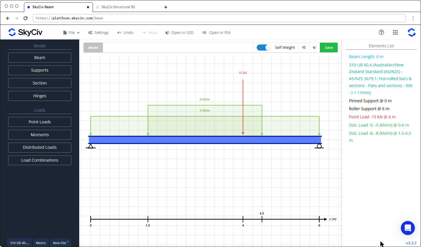
- Section: 310 UB 40.4, AS/NZS 3679.1 Grade 300 (fy = 320 MPa for t < 11 mm)
- Supports: pinned at 0 m, roller at 6 m
- Dead load (G): 5 kN/m over the full span, plus self weight
- Live load (Q): 8 kN/m from 1.5 m to 4.5 m (partial distributed load) and a 15 kN point load at 4 m
- Restraint: the compression flange is laterally restrained at the third points (Ly = LLT = 2 m)
1. Build the beam
Use the left-hand menu to set up the model:
- Beam: set the length (6 m). The Quick Start wizard can create a simply supported beam with a full-span distributed load in one step.
- Supports: pinned at one end and a roller at the other.
- Section: click Launch Section Builder and pick a shape from Database Shapes (here Australian > Steel (300 Grade) > Universal beams > 310 UB 40.4). When asked to assign a material, choose Open Database and pick the steel grade (Steel > Australian/New Zealand Standard (AS/NZS) > AS/NZS 3679.1: Hot-rolled bars & sections > Flats and sections > 300), then click Submit.
- Point Loads and Distributed Loads: enter the position, magnitude and Load Case of each load. The full-span 5 kN/m load is a Dead Load. The 8 kN/m partial load and the 15 kN point load are Live Load. A partial distributed load is just a distributed load with a start position and an end position inside the span.
- Turn on Self Weight in the top bar so the member’s weight is included as a dead load.
2. Add load combinations
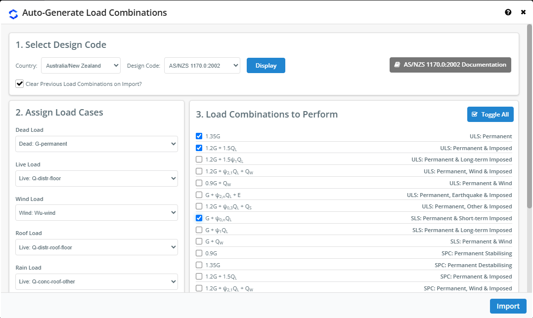
The design module checks the beam for the load combinations in the model, so add at least one. Open Load Combinations and either add rows by hand or click Import from Design Code. For Australian design, choose Australia/New Zealand and AS/NZS 1170.0:2002, click Display, tick the combinations you need, and click Import.
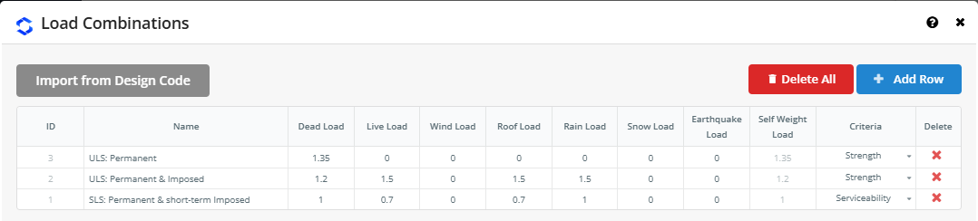
Each combination has a Criteria column. Strength combinations are used for the strength checks and Serviceability combinations for the deflection check. Click Save to close the dialog.
3. Solve
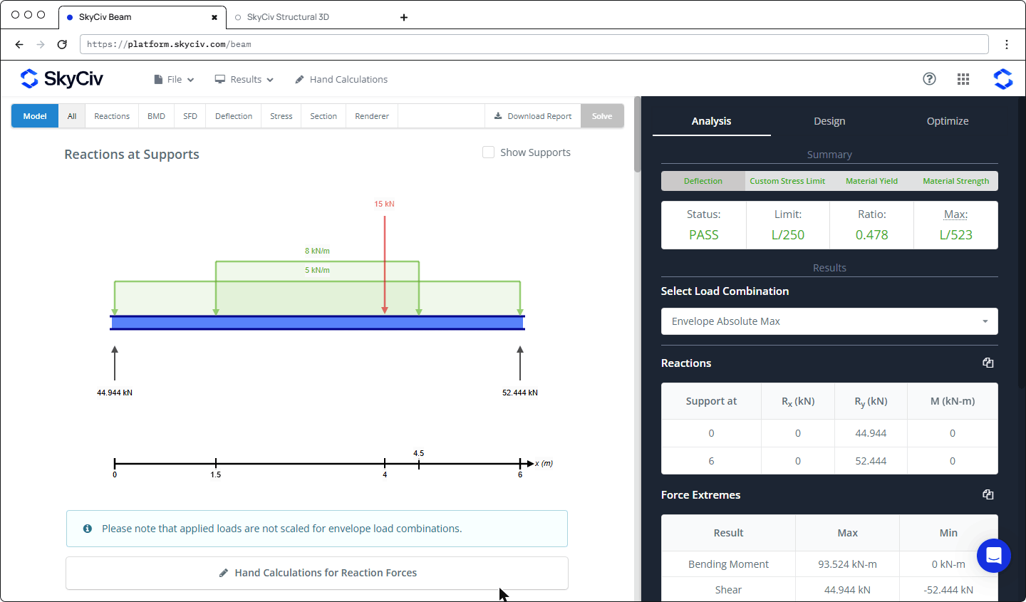
Click Solve. The results appear on the left (reactions, BMD, SFD, deflection, stress and more), and the right-hand panel has three tabs: Analysis, Design and Optimize.
4. Select the design code
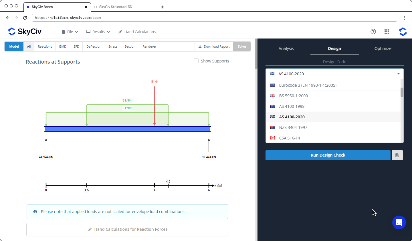
Open the Design tab and choose a code from the Design Code dropdown, here AS 4100-2020.
5. Check the design inputs
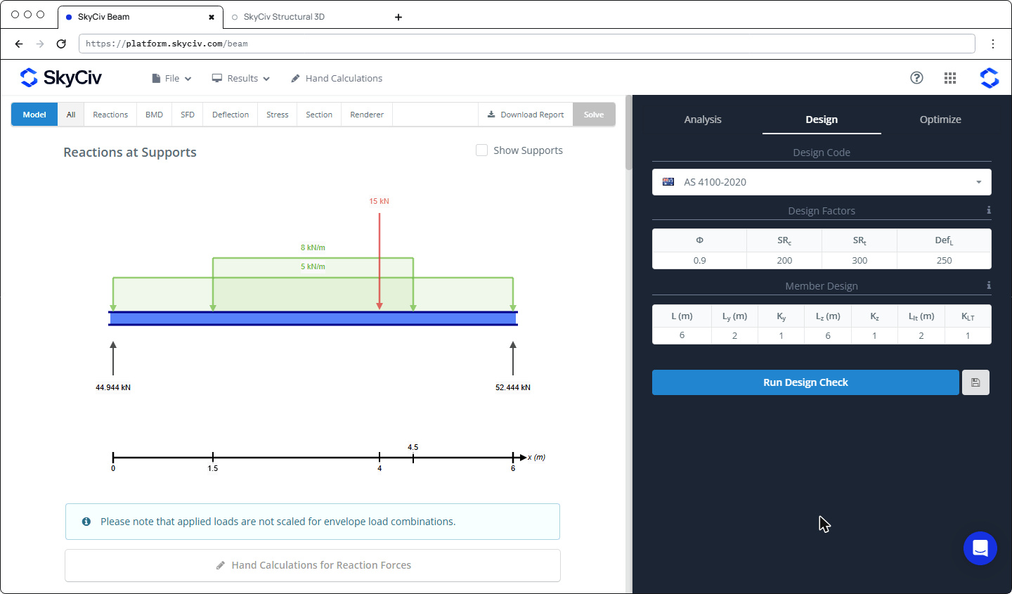
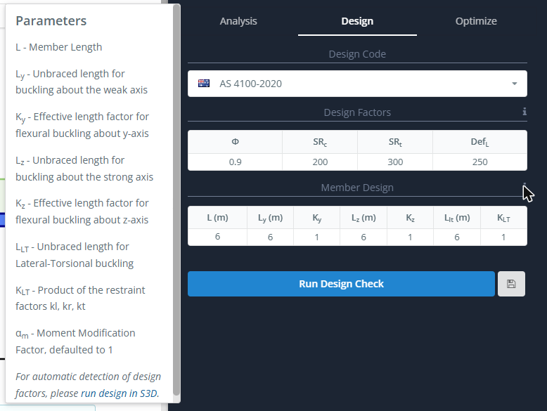
The Design tab shows two small tables. Every cell can be edited. Click the ℹ icons for a description of each input.
Design Factors
| Input | Description | Default |
|---|---|---|
| Φ | Capacity factor (AS 4100 Table 3.4) | 0.9 |
| SRc | Slenderness ratio limit in compression | 200 |
| SRt | Slenderness ratio limit in tension | 300 |
| DefL | Deflection limit ratio (span / DefL) | 250 |
Member Design
| Input | Description | Default |
|---|---|---|
| L | Member length | Beam length |
| Ly | Unbraced length for buckling about the weak (y) axis | Beam length |
| Ky | Effective length factor for flexural buckling about the y-axis | 1 |
| Lz | Unbraced length for buckling about the strong (z) axis | Beam length |
| Kz | Effective length factor for flexural buckling about the z-axis | 1 |
| LLT | Unbraced length for lateral-torsional buckling | Beam length |
| KLT | Product of the restraint factors kl, kr and kt | 1 |
The moment modification factor αm is fixed at 1, which is conservative. By default every unbraced length equals the full span, which assumes no intermediate lateral restraint. In this example the compression flange is restrained at the third points, so Ly and LLT are changed to 2 m.
Tip: Click the save icon next to Run Design Check to save the file together with its design factors.
6. Run the design check
Click Run Design Check. The Quick Ratio Summary shows the worst ratio of each check across all segments of the beam:
| Symbol | Check |
|---|---|
| D | Deflection |
| P | Axial |
| M | Moment |
| V | Shear |
| C | Combined axial and bending |
| CB | Combined buckling |
| BC | Buckling (compression) |
| BB | Buckling (bending) |
| SL | Slenderness |
Ratios below 1.0 are green (pass) and ratios above 1.0 are red (fail). NR means the check was not run. For AS 4100-2020, SL always shows NR because no slenderness limit check is carried out for this code (the SRc and SRt inputs have no effect).
Click a symbol in the Results row to see that check per segment: status, capacity and ratio. Click Reset Design to go back to the inputs, for example to change a length or the design code and run again.
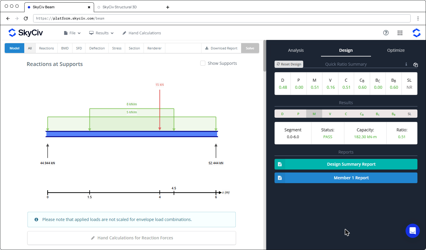
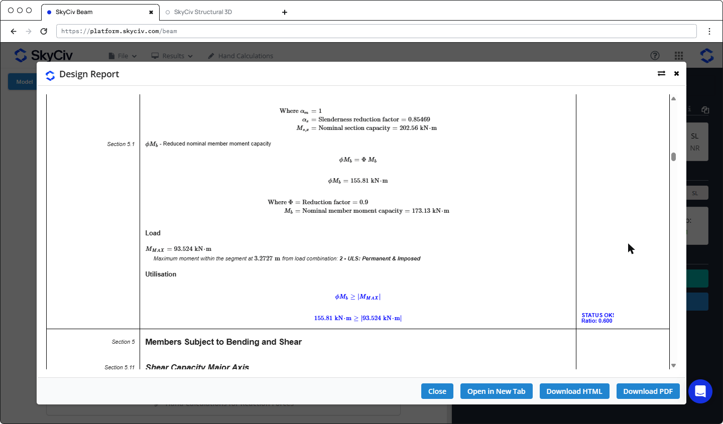
In this example the beam passes. Member moment capacity governs (BB = 0.60): φMb = 155.81 kN·m against M* = 93.52 kN·m from 1.2G + 1.5Q. The section moment capacity is φMs = 182.30 kN·m (M = 0.51), and the deflection ratio is 0.48 (L/523 against the L/250 limit).
7. Reports
Two reports are available under Reports:
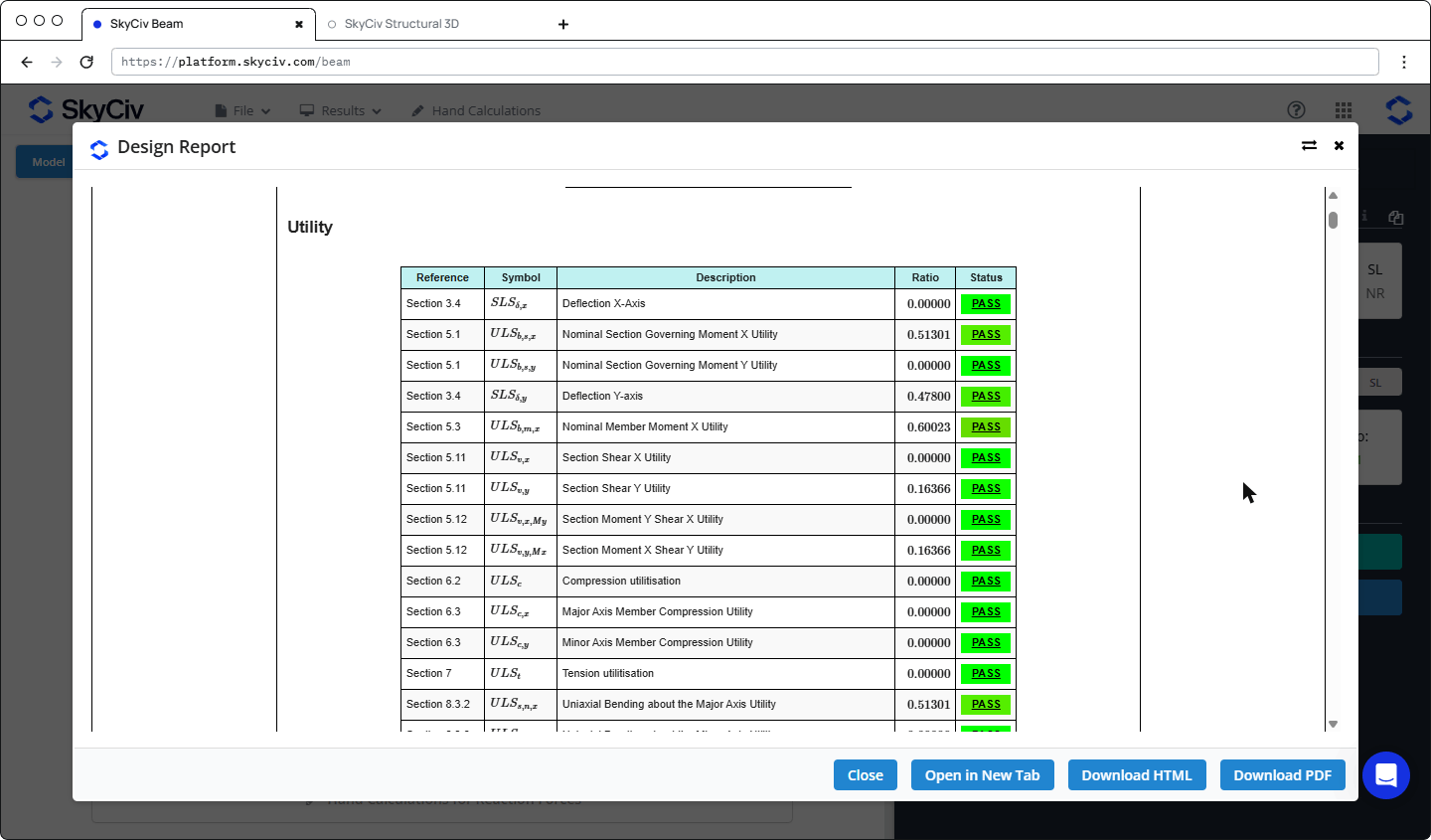
- Member 1 Report: the full AS 4100-2020 calculation report for the beam. It starts with the project details and a Utility table listing every check with its clause reference, ratio and status, followed by step-by-step calculations.
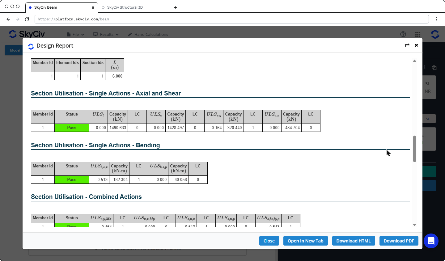
- Design Summary Report: an overview of the design code, the load combinations used, the section capacities and the section and member utilisation tables.
Both reports open in a dialog with Open in New Tab, Download HTML and Download PDF buttons.
8. Optimize the section
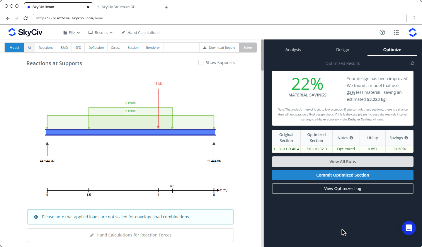
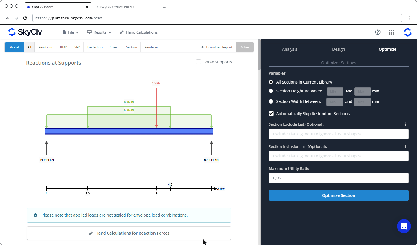
The Optimize tab finds the lightest section from the current library that passes the selected design code. You can search the whole library or limit the search to a range of section heights or widths. You can also exclude or include sections by name, and set the Maximum Utility Ratio (0.95 by default). Click Optimize Section to run it.
The results compare the original and optimised sections, with the utility ratio and the material saving. Here the optimizer suggests a 310 UB 32.0 (utility 0.857, about 22% less material). Click Commit Optimized Section to apply it, then solve and run the design check again to confirm the result.