
To design a bolted flange plate moment connection to AISC 360, you turn the beam end moment into a pair of flange forces and check everything that force passes through. That means slip of the flange bolts, ρουλεμάν μπουλονιών και σχίσιμο, διάτμηση μπλοκ, tension and compression in the flange plate, tension and flexural rupture of the beam at the holes, the weld to the column, and the column flange and web. A separate web plate carries the shear and is checked like a shear tab.
This page works through one real example from start to finish: a W24x84 beam framing into the flange of a W14x211 column, με α 300 kip-ft moment, ένα 250 kip shear and 100 kip of axial load, σχεδιασμένο για AISC 360-16 LRFD and the AISC Manual 15th Edition. The flange plates are 1/2 in thick with eight 1 in A490 slip-critical bolts each, and the web plate is 1 in thick with ten 1 in A490-N bolts. Every equation is written out with its numbers, in the same order as the AISC calc sheet the Σχεδιασμός σύνδεσης SkyCiv module produces for it.
What is a flange plate moment connection?
A flange plate moment connection transfers a beam’s end moment to a column through two plates, one at each beam flange. Each plate is shop-welded to the column flange and field-bolted to the beam flange, and a separate web plate carries the shear. It is a fully restrained (FR) Η σύνδεση πλάκας γιακά είναι πολύ παρόμοια με την under AISC 360-16 B3.4(σι).
It is also called a bolted flange plate or flange-plated moment connection. Fabricators like it because all the welding happens in the shop and the beam is only bolted in the field. The flange plates carry the moment as a tension and compression couple, the web plate is a single plate connection (a shear tab) for the shear, and the column has to take the concentrated flange forces. You can check this one directly in the flange plate connection calculator, and the other types are on the στιγμιαίες συνδέσεις σελίδα.
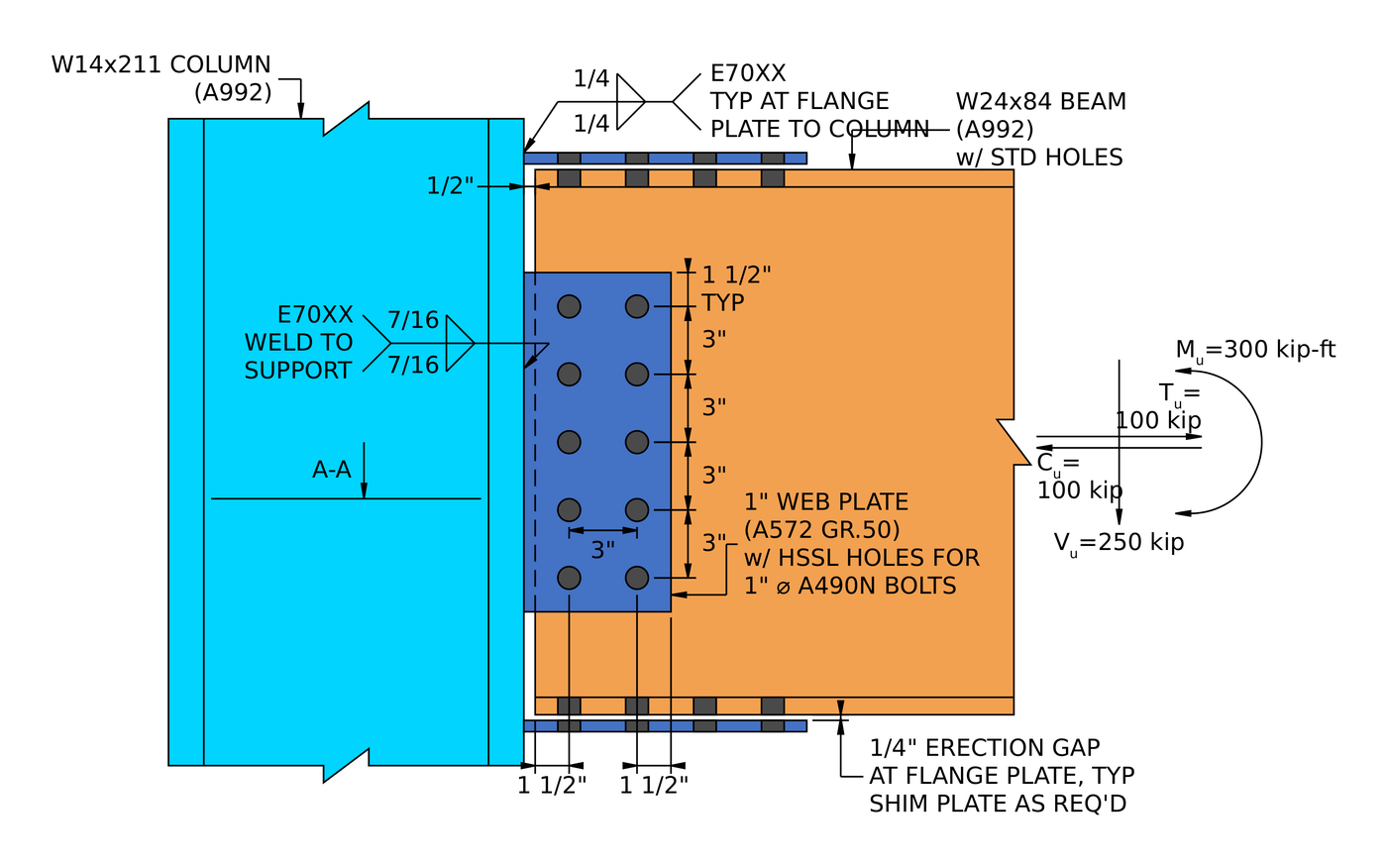
Elevation of the example connection. The flange plates are welded to the column with 1/4 in fillets and bolted to the beam flanges. The web plate is welded with 7/16 in fillets and bolted to the beam web. Υπάρχει ένα 1/4 in erection gap at each flange plate, filled with shims as required.
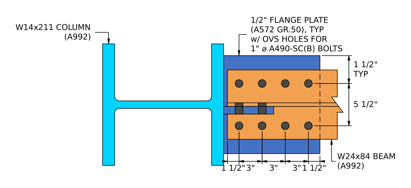
Section A-A. Each flange plate has two lines of four bolts at a 5 1/2 in gage, in oversized holes in the plate and standard holes in the beam flange.
How do you design a flange plate moment connection? The steps at a glance
The flange plate connection is checked first, for the flange force from the moment and axial load. The web plate is checked second, for the shear.
- Check the detailing limits at the beam flange: gage, απόσταση και αποστάσεις άκρων.
- Find the flange force and check slip of the slip-critical bolts.
- Check bolt bearing and tear-out on the flange plate.
- Check bolt bearing and tear-out on the beam flange.
- Check block shear of the flange plate for three tear-out patterns.
- Check block shear of the beam flange.
- Check tension yielding and rupture of the flange plate.
- Check tension rupture of the beam, with shear lag.
- Check flexural rupture of the beam at the flange bolt holes.
- Check the flange plate in compression.
- Check the detailing limit at the column face.
- Check the fillet weld from the flange plate to the column flange.
- Check the column flange and web for the concentrated flange force.
- Check the detailing limits for the web plate.
- Check bolt group shear on the web plate.
- Check bolt bearing and tear-out on the web plate.
- Check bolt bearing and tear-out on the beam web.
- Combine shear, bearing and tear-out per bolt for the effective group strength.
- Check block shear of the web plate.
- Check shear yielding and shear rupture of the web plate.
- Check the detailing limit for the web plate weld.
- Check the fillet weld from the web plate to the column flange.
Design inputs for this example
The design code is AISC 360-16 LRFD. Section properties are from the AISC Manual.
| Είδος | Σύμβολο | αξία |
|---|---|---|
| Factored vertical shear | [mathin] V_{u} [mathin] | 250 δέρμα μόσχου ακατέργαστου |
| Factored axial tension | [mathin] T_{u} [mathin] | 100 δέρμα μόσχου ακατέργαστου |
| Factored axial compression | [mathin] C_{u} [mathin] | 100 δέρμα μόσχου ακατέργαστου |
| Factored strong-axis moment | [mathin] M_{ux} [mathin] | 300 kip-ft |
| Είδος | Σύμβολο | αξία |
|---|---|---|
| Δέσμη | W24x84, A992 | |
| Beam depth | [mathin] d_{bm} [mathin] | 24.1 σε |
| Beam web thickness | [mathin] t_{wb} [mathin] | 0.47 σε |
| Beam flange width / πάχος | [mathin] b_{fb},\ t_{fb} [mathin] | 9.02 σε / 0.77 σε |
| Beam area | [mathin] A_{bm} [mathin] | 24.7 in² |
| Beam elastic section modulus | [mathin] S_{x} [mathin] | 196.46 in³ |
| Beam yield / εφελκυστική τάση | [mathin] F_{yb},\ F_{ub} [mathin] | 50 ksi / 65 ksi |
| Στήλη | W14x211, A992 | |
| Column depth | [mathin] d_{sup} [mathin] | 15.7 σε |
| Column web thickness | [mathin] t_{ws} [mathin] | 0.98 σε |
| Column flange width / πάχος | [mathin] b_{fs},\ t_{fs} [mathin] | 15.8 σε / 1.56 σε |
| Επιφάνεια στήλης | [mathin] A_{sup} [mathin] | 62 in² |
| Column kdes / T dimension | [mathin] k_{des},\ T [mathin] | 2.16 σε / 10 σε |
| Column yield / εφελκυστική τάση | [mathin] F_{ys},\ F_{us} [mathin] | 50 ksi / 65 ksi |
| Modulus of elasticity | [mathin] E [mathin] | 29000 ksi |
| Flange plate connection | Σύμβολο | αξία |
|---|---|---|
| Πλάκα φλάντζας | PL 1/2 Χ 12 3/4 Χ 12 1/2, A572 Gr. 50 | |
| Plate width / μήκος / πάχος | [mathin] b_{fp},\ L_{fp},\ t_{fp} [mathin] | 12.75 σε / 12.5 σε / 0.5 σε |
| Plate yield / εφελκυστική τάση | [mathin] F_{yp},\ F_{up} [mathin] | 50 ksi / 65 ksi |
| Μπουλόνια | 1 in A490-SC, Class B, one slip plane | |
| Bolt nominal tensile / τάση διάτμησης | [mathin] F_{nt},\ F_{nv} [mathin] | 113 ksi / 68 ksi |
| Holes in plate / beam flange | Oversized (OVS) / πρότυπο (ΣΜΝ) | |
| Bolt rows / gage | [mathin] n_{r},\ g_{a} [mathin] | 2 / 5.5 σε |
| Bolt columns / column spacing | [mathin] n_{c},\ s_{c} [mathin] | 4 / 3 σε |
| Κατακόρυφος / horizontal edge distance on beam flange | [mathin] L_{ev,bf},\ L_{eh,bf} [mathin] | 1.76 σε / 1.5 σε |
| Κατακόρυφος / horizontal edge distance on flange plate | [mathin] L_{ev,fp},\ L_{eh,fp} [mathin] | 3.625 σε / 1.5 σε |
| Unbraced length of flange plate | [mathin] L_{k,fp} [mathin] | 3 σε |
| Συγκόλληση, flange plate to column | [mathin] W,\ F_{EXX} [mathin] | 1/4 σε (0.25 σε) φιλέτο, Ε70ΧΧ, 70 ksi |
| Web plate connection | Σύμβολο | αξία |
|---|---|---|
| Πλάκα Ιστού (ενιαίο πιάτο) | PL 1 Χ 6 1/2 Χ 15, A572 Gr. 50 | |
| Plate width / βάθος / πάχος | [mathin] b_{p},\ d_{p},\ t_{p} [mathin] | 6.5 σε / 15 σε / 1 σε |
| Plate yield / εφελκυστική τάση | [mathin] F_{yp},\ F_{up} [mathin] | 50 ksi / 65 ksi |
| Μπουλόνια | 1 in A490-N, single shear | |
| Bolt nominal tensile / τάση διάτμησης | [mathin] F_{nt},\ F_{nv} [mathin] | 113 ksi / 68 ksi |
| Holes in plate / beam web | Short-slotted horizontal (HSSL) / πρότυπο (ΣΜΝ) | |
| Bolt rows / row spacing | [mathin] n_{r},\ s_{r} [mathin] | 5 / 3 σε |
| Bolt columns / column spacing | [mathin] n_{c},\ s_{c} [mathin] | 2 / 3 σε |
| Beam web clearance to column | [mathin] clr [mathin] | 0.5 σε |
| Horizontal edge distance on beam web / πλάκα | [mathin] L_{eh,bm},\ L_{eh,pl} [mathin] | 1.5 σε / 1.5 σε |
| Vertical edge distance on plate | [mathin] L_{ev,pl} [mathin] | 1.5 σε |
| Bolt group eccentricity | [mathin] e [mathin] | 3.5 σε |
| Συγκόλληση, web plate to column | [mathin] W,\ F_{EXX} [mathin] | 7/16 σε (0.4375 σε) fillet both sides, Ε70ΧΧ, 70 ksi |
Μέρος 1: the flange plate connection
Βήματα 1 προς το 13 check the flange plates, the beam flanges, the welds to the column and the column itself, all for the flange force worked out in Step 2.
Βήμα 1: Detailing limits at the beam flange (AISC 360-16 J3.3, J3.4, J3.5)
Before any strength check, the bolt layout has to be buildable and match the assumptions behind the strength equations. Bolts that are too close tear between the holes, and edges that are too close tear out.
The minimum bolt spacing is [mathin] 2\tfrac{2}{3} d_{b} [mathin] from J3.3. The minimum edge distance for a 1 in bolt is 1 1/4 in from Table J3.4, which is the limit on the beam flange, where the holes are standard. The flange plate has oversized holes, so Table J3.5 adds 1/8 σε, which brings its edge distance limits to 1.375 σε. The gage has its own minimum, so that the two bolt lines fit across the flange with room to install the bolts.
[math] s_{min} = 2\tfrac{2}{3}\, d_{b} = 2.667 \times (1\,in) = 2.667\,in [math]
| Detailing limit | Limit (σε) | Πραγματικός (σε) | DCR | Αποτέλεσμα |
|---|---|---|---|---|
| Minimum bolt gage | 4.875 | 5.500 | 0.886 | cdot K_a |
| Minimum bolt column spacing | 2.667 | 3.000 | 0.889 | cdot K_a |
| Maximum bolt column spacing | 6.000 | 3.000 | 0.500 | cdot K_a |
| Plate minimum vertical edge distance | 1.375 | 3.625 | 0.379 | cdot K_a |
| Plate minimum horizontal edge distance | 1.375 | 1.500 | 0.917 | cdot K_a |
| Beam minimum vertical edge distance | 1.250 | 1.760 | 0.710 | cdot K_a |
| Beam minimum horizontal edge distance | 1.250 | 1.500 | 0.833 | cdot K_a |
For a minimum limit the ratio is limit over actual, and for a maximum it is actual over limit. The governing row is the plate horizontal edge distance:
[math] DCR = \frac{1.375\,in}{1.5\,in} = 0.917 [math]
DCR = 0.917 < 1.0, Εντάξει
Βήμα 2: Flange force and slip critical bolt strength (AISC 360-16 J3.8)
The moment is carried as a couple of equal and opposite forces in the two beam flanges, and the flange plate bolts have to carry that force without slipping. These bolts are slip-critical because the flange plate has oversized holes, which AISC 360-16 J3.2 allows only in slip-critical connections.
Flange force
The moment is divided by the distance between the beam flange centroids, [mathin] d_{bm} – t_{fb} [mathin]. The web plate is designed for shear only, so the axial load goes to the flange plates, half to each:
[math] P_{uF} = \frac{M_{ux}}{d_{bm} – t_{fb}} + \frac{P_{u}}{2} [math]
[math] P_{uF} = \frac{(300\,kip\text{-}ft)}{(24.1\,in) – (0.77\,in)} + \frac{(100\,kip)}{2} [math]
[math] P_{uF} = 204.31\,kip [math]
The axial tension and compression are both 100 δέρμα μόσχου ακατέργαστου, so the flange force is 204.31 kip either way: tension adds to the tension flange and compression adds to the compression flange. Every check in Part 1 uses this one value.
Slip resistance
Οπου [mathin] \phi = 0.85 [mathin] is the resistance factor for oversized holes, [mathin] \mu = 0.5 [mathin] is the mean slip coefficient for Class B faying surfaces, [mathin] D_{u} = 1.13 [mathin] relates the mean installed pretension to the specified minimum, [mathin] h_{f} = 0.85 [mathin] is the filler factor, [mathin] T_{b} = 64\,kip [mathin] is the minimum pretension of a 1 in A490 bolt from Table J3.1, and there is [mathin] N_{s} = 1 [mathin] slip plane:
[math] \phi R_{n} = \phi\, \mu\, D_{u}\, h_{f}\, T_{b}\, N_{s}\, n_{r}\, n_{c} [math]
[math] \phi R_{n} = (0.85) \times (0.5) \times (1.13) \times (0.85) \times (64\,kip) \times (1) \times (2) \times (4) [math]
[math] \phi R_{n} = 209\,kip [math]
DCR = 204.31 δέρμα μόσχου ακατέργαστου / 209 kip = 0.978 < 1.0, Εντάξει
The filler factor of 0.85 is the J3.8 value for two or more fillers between the connected parts. The drawing calls for shims as required at the 1/4 in erection gap, so the design does not count on there being only one. Στο 0.978 this is one of the two tightest checks in the connection.
Βήμα 3: Bolt bearing and tear-out on the flange plate (AISC 360-16 J3.10)
Slip-critical bolts must also have enough strength as bearing bolts, in case the joint does slip. Each bolt pushes on the edge of its hole in the plate. The plate either deforms at the hole (ρουλεμάν, capped at 2.4 Διατμητική Αντοχή Μπουλονιών) or tears a strip out to the next hole or to the end of the plate (tear-out, 1.2 Διατμητική Αντοχή Μπουλονιών). The bolts nearest the end of the plate have the shortest clear distance, so they are the weak ones.
Clear distance for the end bolts, με [mathin] d_{h} = 1.25\,in [mathin], the oversized hole dimension along the member length:
[math] l_{c1} = L_{eh,fp} – \frac{d_{h}}{2} = (1.5\,in) – \frac{(1.25\,in)}{2} = 0.875\,in [math]
Clear distance between the other bolts:
[math] l_{c2} = s_{c} – d_{h} = (3\,in) – (1.25\,in) = 1.75\,in [math]
The end bolt in each of the two lines uses [mathin] l_{c1} [mathin], and the other three in each line use [mathin] l_{c2} [mathin]:
[math] \phi R_{n} = \phi \left[ \min\left(1.2\, l_{c1},\, 2.4\, d_{b}\right) t_{fp} F_{up}\, n_{r} + \min\left(1.2\, l_{c2},\, 2.4\, d_{b}\right) t_{fp} F_{up}\, n_{r} \left( n_{c} – 1 \right) \right] [math]
[math] \phi R_{n} = (0.75) \times \left[ \min\left(1.2 \times 0.875\,in,\, 2.4 \times 1\,in\right)(0.5\,in)(65\,ksi)(2) + \min\left(1.2 \times 1.75\,in,\, 2.4 \times 1\,in\right)(0.5\,in)(65\,ksi)(2)(4 – 1) \right] [math]
[math] \phi R_{n} = 358.31\,kip [math]
DCR = 204.31 δέρμα μόσχου ακατέργαστου / 358.31 kip = 0.570 < 1.0, Εντάξει
Βήμα 4: Bolt bearing and tear-out on the beam flange (AISC 360-16 J3.10)
The same check applies to the beam flange, which has standard holes ([mathin] d_{h} = 1.125\,in [mathin]) and is thicker than the plate.
[math] l_{c1} = L_{eh,bf} – \frac{d_{h}}{2} = (1.5\,in) – \frac{(1.125\,in)}{2} = 0.9375\,in [math]
[math] l_{c2} = s_{c} – d_{h} = (3\,in) – (1.125\,in) = 1.875\,in [math]
[math] \phi R_{n} = \phi \left[ \min\left(1.2\, l_{c1},\, 2.4\, d_{b}\right) t_{fb} F_{ub}\, n_{r} + \min\left(1.2\, l_{c2},\, 2.4\, d_{b}\right) t_{fb} F_{ub}\, n_{r} \left( n_{c} – 1 \right) \right] [math]
[math] \phi R_{n} = (0.75) \times \left[ \min\left(1.2 \times 0.9375\,in,\, 2.4 \times 1\,in\right)(0.77\,in)(65\,ksi)(2) + \min\left(1.2 \times 1.875\,in,\, 2.4 \times 1\,in\right)(0.77\,in)(65\,ksi)(2)(4 – 1) \right] [math]
[math] \phi R_{n} = 591.22\,kip [math]
DCR = 204.31 δέρμα μόσχου ακατέργαστου / 591.22 kip = 0.346 < 1.0, Εντάξει
Βήμα 5: Block shear of the flange plate (AISC 360-16 J4.3)
A block of the flange plate can tear out along the bolt lines: shear along a line of holes plus tension across the plate. With two bolt lines there are three ways for this to happen, and the weakest one governs. Each hole adds 1/16 in for damage during punching (B4.3), και [mathin] d_{h} = 1.25\,in [mathin] for the oversized holes in both directions.
L pattern: one shear plane, tension across the bolts to one edge
[math] A_{nt} = t_{fp} \left[ (n_{r} – 2)\, s_{r} + g_{a} + L_{ev,fp} – (n_{r} – 0.5)\left( d_{h} + 0.0625\,in \right) \right] [math]
[math] A_{nt} = (0.5\,in) \times \left[ (2 – 2)(3\,in) + 5.5\,in + 3.625\,in – (2 – 0.5)(1.25\,in + 0.0625\,in) \right] = 3.5781\,in^{2} [math]
[math] A_{gv} = t_{fp} \left[ L_{eh,fp} + (n_{c} – 1)\, s_{c} \right] = (0.5\,in) \times \left[ 1.5\,in + (4 – 1)(3\,in) \right] = 5.25\,in^{2} [math]
[math] A_{nv} = t_{fp} \left[ L_{eh,fp} + (n_{c} – 1)\, s_{c} – (n_{c} – 0.5)\left( d_{h} + 0.0625\,in \right) \right] = (0.5\,in) \times \left[ 1.5\,in + (3)(3\,in) – (3.5)(1.3125\,in) \right] = 2.9531\,in^{2} [math]
Με [mathin] U_{bs} = 1 [mathin] for uniform tension:
[math] \phi R_{n} = \phi \left( 0.6\, F_{up} A_{nv} + U_{bs} F_{up} A_{nt} \right) \le \phi \left( 0.6\, F_{yp} A_{gv} + U_{bs} F_{up} A_{nt} \right) [math]
[math] \phi R_{n} = (0.75) \left( 0.6 \times 65 \times 2.9531 + 1 \times 65 \times 3.5781 \right) \le (0.75) \left( 0.6 \times 50 \times 5.25 + 1 \times 65 \times 3.5781 \right) [math]
[math] \phi R_{n} = 260.81\,kip [math]
U pattern: two shear planes, tension between the bolt lines
[math] A_{gv} = 2\, t_{fp} \left[ L_{eh,fp} + (n_{c} – 1)\, s_{c} \right] = 2 \times (0.5\,in) \times \left[ 1.5\,in + (3)(3\,in) \right] = 10.5\,in^{2} [math]
[math] A_{nv} = 2\, t_{fp} \left[ L_{eh,fp} + (n_{c} – 1)\, s_{c} – (n_{c} – 0.5)\left( d_{h} + 0.0625\,in \right) \right] = 5.9062\,in^{2} [math]
[math] A_{nt} = t_{fp} \left[ (n_{r} – 2)\, s_{r} + g_{a} – (n_{r} – 1)\left( d_{h} + 0.0625\,in \right) \right] = (0.5\,in) \times \left[ 0 + 5.5\,in – (1)(1.3125\,in) \right] = 2.0937\,in^{2} [math]
[math] \phi R_{n} = (0.75) \left( 0.6 \times 65 \times 5.9062 + 1 \times 65 \times 2.0937 \right) \le (0.75) \left( 0.6 \times 50 \times 10.5 + 1 \times 65 \times 2.0937 \right) = 274.83\,kip [math]
2L pattern: two shear planes, tension from each bolt line to its edge
[math] A_{nt} = 2\, t_{fp} \left[ L_{ev,fp} – 0.5\left( d_{h} + 0.0625\,in \right) \right] = 2 \times (0.5\,in) \times \left[ 3.625\,in – 0.5 \times (1.3125\,in) \right] = 2.9687\,in^{2} [math]
[math] \phi R_{n} = (0.75) \left( 0.6 \times 65 \times 5.9062 + 1 \times 65 \times 2.9687 \right) \le (0.75) \left( 0.6 \times 50 \times 10.5 + 1 \times 65 \times 2.9687 \right) = 317.48\,kip [math]
Governing block shear
[math] \phi R_{n} = \min\left( 260.81\,kip,\, 274.83\,kip,\, 317.48\,kip \right) = 260.81\,kip [math]
DCR = 204.31 δέρμα μόσχου ακατέργαστου / 260.81 kip = 0.783 < 1.0, Εντάξει
The L pattern governs because it has only one shear plane. ο 12.75 in plate is wider than the 9.02 in beam flange, which gives the outer strips plenty of tension area in the 2L pattern.
Βήμα 6: Block shear of the beam flange (AISC 360-16 J4.3)
The beam flange can tear out the same way. Its edges are only 1.76 in outside the bolt lines, so the critical block is the 2L pattern: the two outer strips of flange shear along the bolt lines and pull away in tension.
[math] A_{nt} = t_{fb} \left[ b_{fb} – g_{a} – (n_{r} – 1)\left( d_{h} + 0.0625\,in \right) \right] = (0.77\,in) \times \left[ 9.02\,in – 5.5\,in – (1)(1.125\,in + 0.0625\,in) \right] = 1.796\,in^{2} [math]
[math] A_{gv} = 2\, t_{fb} \left[ L_{eh,bf} + (n_{c} – 1)\, s_{c} \right] = 2 \times (0.77\,in) \times \left[ 1.5\,in + (3)(3\,in) \right] = 16.17\,in^{2} [math]
[math] A_{nv} = 2\, t_{fb} \left[ L_{eh,bf} + (n_{c} – 1)\, s_{c} – (n_{c} – 0.5)\left( d_{h} + 0.0625\,in \right) \right] = 2 \times (0.77\,in) \times \left[ 10.5\,in – (3.5)(1.1875\,in) \right] = 9.7694\,in^{2} [math]
[math] \phi R_{n} = (0.75) \left( 0.6 \times 65 \times 9.7694 + 1 \times 65 \times 1.796 \right) \le (0.75) \left( 0.6 \times 50 \times 16.17 + 1 \times 65 \times 1.796 \right) [math]
[math] \phi R_{n} = 373.31\,kip [math]
DCR = 204.31 δέρμα μόσχου ακατέργαστου / 373.31 kip = 0.547 < 1.0, Εντάξει
Βήμα 7: Tension yielding and rupture of the flange plate (AISC 360-16 J4.1)
On the tension side, the flange plate is a short tension member. Its gross section must not yield, and its net section through the row of holes must not rupture.
Tension yielding (Εξ. J4-1)
[math] \phi R_{n,ty} = \phi\, F_{yp}\, t_{fp}\, b_{fp} = (0.9) \times (50\,ksi) \times (0.5\,in) \times (12.75\,in) = 286.88\,kip [math]
Tension rupture (Εξ. J4-2)
[math] \phi R_{n,tr} = \phi\, F_{up}\, t_{fp} \left[ b_{fp} – n_{r}\left( d_{h} + 0.0625\,in \right) \right] [math]
[math] \phi R_{n,tr} = (0.75) \times (65\,ksi) \times (0.5\,in) \times \left[ 12.75\,in – (2) \times (1.25\,in + 0.0625\,in) \right] = 246.8\,kip [math]
[math] \phi R_{n} = \min\left( 286.88\,kip,\, 246.8\,kip \right) = 246.8\,kip [math]
DCR = 204.31 δέρμα μόσχου ακατέργαστου / 246.8 kip = 0.828 < 1.0, Εντάξει
Βήμα 8: Tension rupture of the beam with shear lag (AISC 360-16 D3, J4.1)
The flange force has to get into the beam as well. Half the beam, a WT made of one flange and half the web, is treated as the tension member. The bolts connect only the flange, so the web lags behind in picking up stress, and the shear lag factor U reduces the effective net area.
From Table D3.1 case 2, όπου [mathin] \bar{y} = 3.0217\,in [mathin] is the distance from the flange to the centroid of the WT and l is the length of the connection, from the first bolt column to the last:
[math] U = 1 – \frac{\bar{y}}{l} = 0.66439 [math]
[math] \phi R_{n,tr} = \phi\, F_{ub}\, U \left[ 0.5\, A_{bm} – n_{r}\left( d_{h} + 0.0625\,in \right) t_{fb} \right] [math]
[math] \phi R_{n,tr} = (0.75) \times (65\,ksi) \times (0.66439) \times \left[ 0.5 \times (24.7\,in^{2}) – (2) \times (1.125\,in + 0.0625\,in) \times (0.77\,in) \right] [math]
[math] \phi R_{n,tr} = 340.78\,kip [math]
DCR = 204.31 δέρμα μόσχου ακατέργαστου / 340.78 kip = 0.600 < 1.0, Εντάξει
Βήμα 9: Flexural rupture of the beam at the flange bolt holes (AISC 360-16 F13.1)
The bolt holes take material out of the beam’s tension flange right where the moment is largest. F13.1 checks whether those holes reduce the beam’s flexural strength, and if they do, by how much.
Gross and net area of the tension flange
[math] A_{fg} = b_{fb}\, t_{fb} = (9.02\,in) \times (0.77\,in) = 6.9454\,in^{2} [math]
[math] A_{fn} = A_{fg} – n_{r}\left( d_{h} + 0.0625\,in \right) t_{fb} = (6.9454\,in^{2}) – (2) \times (1.125\,in + 0.0625\,in) \times (0.77\,in) = 5.1166\,in^{2} [math]
Does tensile rupture apply?
[math] \frac{F_{y}}{F_{u}} = \frac{50\,ksi}{65\,ksi} = 0.76923 \le 0.8 \;\Rightarrow\; Y_{t} = 1 [math]
[math] F_{u} A_{fn} = (65\,ksi) \times (5.1166\,in^{2}) = 332.58\,kip [math]
[math] Y_{t} F_{y} A_{fg} = (1) \times (50\,ksi) \times (6.9454\,in^{2}) = 347.27\,kip [math]
Επειδή [mathin] F_{u} A_{fn} \lt Y_{t} F_{y} A_{fg} [mathin], the net flange ruptures before the gross flange yields, so the limit state of tensile rupture applies.
Flexural strength at the holes (Εξ. F13-1)
[math] M_{n} = \frac{F_{ub} A_{fn}}{A_{fg}}\, S_{x} = \frac{(65\,ksi) \times (5.1166\,in^{2})}{(6.9454\,in^{2})} \times (196.46\,in^{3}) = 783.95\,kip\text{-}ft [math]
As a flange force, to compare with [mathin] P_{uF} [mathin]:
[math] \phi R_{n} = \frac{\phi\, M_{n}}{d_{bm} – t_{fb}} = \frac{(0.9) \times (783.95\,kip\text{-}ft)}{(24.1\,in) – (0.77\,in)} = 362.91\,kip [math]
DCR = 204.31 δέρμα μόσχου ακατέργαστου / 362.91 kip = 0.563 < 1.0, Εντάξει
Βήμα 10: Compression strength of the flange plate (AISC 360-16 J4.4)
On the compression side the flange plate is a short column. If it is stocky enough, it reaches its yield load without buckling, και AISC 360-16 J4.4 lets you skip the full Chapter E column check.
The report takes the unbraced length of the plate as [mathin] L_{k,fp} = 3\,in [mathin] με [mathin] K = 1.2 [mathin], the recommended design value in Commentary Table C-A-7.1 for a member fixed against rotation at both ends but free to translate at one. For a rectangular plate, [mathin] r = t_{fp} / \sqrt{12} [mathin]:
[math] \frac{K L}{r} = \frac{(1.2) \times (3\,in)}{(0.5\,in) / \sqrt{12}} = 24.942 \le 25 [math]
Since KL/r is no more than 25, Εξ. J4-6 applies:
[math] \phi R_{n} = \phi\, F_{yp}\, t_{fp}\, b_{fp} = (0.9) \times (50\,ksi) \times (0.5\,in) \times (12.75\,in) = 286.88\,kip [math]
DCR = 204.31 δέρμα μόσχου ακατέργαστου / 286.88 kip = 0.712 < 1.0, Εντάξει
The ratio of 24.942 is just under the limit of 25. A thinner plate or a longer unbraced length would push the plate into the Chapter E buckling equations.
Βήμα 11: Detailing limit at the column face
The flange plate weld sits in the gap between the column flange and the end of the beam, so the weld cannot be larger than the beam clearance.
[math] DCR = \frac{W}{clr} = \frac{0.25\,in}{0.5\,in} = 0.5 [math]
DCR = 0.500 < 1.0, Εντάξει
Βήμα 12: Fillet weld capacity, flange plate to column flange (AISC 360-16 J2.4)
The whole flange force passes through the fillet welds that join the flange plate to the column. Their fillet weld capacity depends on size, length and load direction. The base metal on either side of the weld, here the plate and the column flange, can also limit how much of the weld size counts.
Base metal limit on weld size (AISC Manual Eq. 9-2)
[math] D_{max} = \frac{ \min\left( \frac{t_{fp}}{2} F_{up},\; t_{fs} F_{us} \right) }{3.09\,kip/in \times \left( F_{EXX} / 70\,ksi \right)} = \frac{ \min\left( (0.25\,in)(65\,ksi),\; (1.56\,in)(65\,ksi) \right) }{(3.09\,kip/in)(1)} = 5.2589 [math]
So up to 5.26/16 in of weld size counts. ο 1/4 σε (4/16 σε) weld is below that, so its full size is used.
Effective length
The weld runs across the plate width on both faces of the plate, each line reduced by 2W at the ends. The plate is narrower than the column flange, so the plate width sets the length:
[math] L_{w} = 2 \left[ \min\left( b_{fp},\, b_{fs} \right) – 2W \right] = 2 \times \left[ \min\left( 12.75\,in,\, 15.8\,in \right) – 2 \times (0.25\,in) \right] = 24.5\,in [math]
Αντοχή συγκόλλησης
The flange force acts perpendicular to the weld lines, Έτσι [mathin] \theta = 90^{\circ} [mathin] and the directional factor [mathin] 1 + 0.5 \sin^{1.5}\theta [mathin] είναι 1.5:
[math] \phi R_{n} = \phi\, 0.6\, F_{EXX} \frac{\sqrt{2}}{2} \min\left( W,\, \frac{D_{max}}{16} \right) (1.5)\, L_{w} [math]
[math] \phi R_{n} = (0.75) \times 0.6 \times (70\,ksi) \times \frac{\sqrt{2}}{2} \times (0.25\,in) \times (1.5) \times (24.5\,in) [math]
[math] \phi R_{n} = 204.64\,kip [math]
DCR = 204.31 δέρμα μόσχου ακατέργαστου / 204.64 kip = 0.998 < 1.0, Εντάξει
This is the governing check of the whole connection. ο 1/4 in weld carries the flange force with almost nothing to spare, and only because the 1.5 directional factor applies. Without it, the weld would need to be about 3/8 σε.
Βήμα 13: Column flange and web under the flange force (AISC 360-16 J10)
Each flange plate delivers its force to the column as a concentrated load. The column flange can bend, the web can yield, cripple or buckle under it, and the panel zone has to carry the moment as shear. If any of these fail, the column needs stiffeners or a doubler plate, or a heavier section.
Flange local bending (Εξ. J10-1)
[math] \phi R_{n,flb} = \phi\, 6.25\, F_{ys}\, t_{fs}^{2} = (0.9) \times 6.25 \times (50\,ksi) \times (1.56\,in)^{2} = 684.45\,kip [math]
Web compression buckling (Εξ. J10-8)
The report uses the column’s T dimension, [mathin] T_{sup} = 10\,in [mathin], for the web depth in this equation, με [mathin] Q_{f} = 1 [mathin]:
[math] \phi R_{n,wcb} = \phi \left( \frac{24\, t_{ws}^{3} \sqrt{E\, F_{ys}}}{T_{sup}} \right) Q_{f} = (0.9) \times \left( \frac{24 \times (0.98\,in)^{3} \times \sqrt{(29000\,ksi) \times (50\,ksi)}}{(10\,in)} \right) \times (1) = 2448\,kip [math]
Strictly, J10.5 applies when compressive forces act on both column flanges at the same level, as when beams frame in from both sides. Checking it for a one-sided connection is conservative, and here it is nowhere near governing.
Web local crippling (Εξ. J10-4)
The length of bearing [mathin] l_{b} = 0.5\,in [mathin] is the flange plate thickness:
[math] \phi R_{n,wlc} = \phi\, 0.8\, t_{ws}^{2} \left[ 1 + 3 \left( \frac{l_{b}}{d_{sup}} \right) \left( \frac{t_{ws}}{t_{fs}} \right)^{1.5} \right] \sqrt{\frac{E\, F_{ys}\, t_{fs}}{t_{ws}}}\, Q_{f} [math]
[math] \phi R_{n,wlc} = (0.75) \times 0.8 \times (0.98\,in)^{2} \times \left[ 1 + 3 \times \left( \frac{0.5\,in}{15.7\,in} \right) \times \left( \frac{0.98\,in}{1.56\,in} \right)^{1.5} \right] \times \sqrt{\frac{(29000\,ksi) \times (50\,ksi) \times (1.56\,in)}{(0.98\,in)}} \times (1) = 917.11\,kip [math]
Web local yielding (Εξ. J10-2)
[math] \phi R_{n,wly} = \phi\, F_{ys}\, t_{ws} \left( 5\, k_{des} + l_{b} \right) = (1) \times (50\,ksi) \times (0.98\,in) \times \left( 5 \times 2.16\,in + 0.5\,in \right) = 553.7\,kip [math]
Panel zone web shear (Εξ. J10-9)
[math] \phi R_{n,wpz} = \phi\, 0.6\, F_{ys}\, d_{sup}\, t_{ws} = (0.9) \times 0.6 \times (50\,ksi) \times (15.7\,in) \times (0.98\,in) = 415.42\,kip [math]
Governing column strength
[math] \phi R_{n} = \min\left( 684.45,\, 2448,\, 917.11,\, 553.7,\, 415.42 \right) = 415.42\,kip [math]
DCR = 204.31 δέρμα μόσχου ακατέργαστου / 415.42 kip = 0.492 < 1.0, Εντάξει
The W14x211 column has a 1.56 in flange and a 0.98 in web, so it needs no stiffeners or doubler plate for this flange force. Panel zone shear governs the column checks.
Μέρος 2: the web plate connection
Βήματα 14 προς το 22 check the web plate, a single plate connection that carries the 250 kip shear. Because the flange plates make the joint fully restrained, the web plate does not have to rotate like a simple shear tab, and the checks that exist only to keep a shear tab flexible are not part of this design.
Βήμα 14: Detailing limits for the web plate (AISC 360-16 J3.3, J3.4, J3.5)
The web plate bolt layout has to meet the same spacing and edge distance rules, and the plate has to be deep enough to stabilise the beam web while still fitting between the beam flanges.
The plate has horizontal short-slotted holes. The horizontal edge distance is measured along the slot, so Table J3.5 adds 1/8 in and the limit becomes 1.375 σε. The vertical edge distance is measured across the slot and stays at 1.25 σε.
| Detailing limit | Limit (σε) | Πραγματικός (σε) | DCR | Αποτέλεσμα |
|---|---|---|---|---|
| Minimum bolt row spacing | 2.667 | 3.000 | 0.889 | cdot K_a |
| Maximum bolt row spacing | 6.000 | 3.000 | 0.500 | cdot K_a |
| Minimum bolt column spacing | 2.667 | 3.000 | 0.889 | cdot K_a |
| Maximum bolt column spacing | 6.000 | 3.000 | 0.500 | cdot K_a |
| Plate minimum vertical edge distance | 1.250 | 1.500 | 0.833 | cdot K_a |
| Plate minimum horizontal edge distance | 1.375 | 1.500 | 0.917 | cdot K_a |
| Beam minimum horizontal edge distance | 1.250 | 1.500 | 0.833 | cdot K_a |
| Minimum connection depth | 10.000 | 15.000 | 0.667 | cdot K_a |
| Maximum connection depth | 20.750 | 15.000 | 0.723 | cdot K_a |
[math] DCR = \frac{1.375\,in}{1.5\,in} = 0.917 [math]
DCR = 0.917 < 1.0, Εντάξει
Βήμα 15: Bolt group shear on the web plate (AISC 360-16 J3.6)
The ten web bolts share the 250 kip shear. In a simple shear tab, the eccentricity of the reaction would reduce the group to fewer than ten bolts’ worth of strength. Here the report uses a bolt group coefficient C = 10, the full bolt count, because the end moment is taken by the flange plates and the web bolts carry the shear directly.
Οπου [mathin] \phi = 0.75 [mathin], [mathin] F_{nv} = 68\,ksi [mathin] for an A490-N bolt, [mathin] N_{s} = 1 [mathin] shear plane, και [mathin] h_{f} = 1 [mathin] because there are no fillers (J5.2(ένα)):
[math] h_{f} = 1 – 0.4 \left( t – 0.25\,in \right) = 1 – 0.4 \left( 0\,in – 0.25\,in \right) \le 1 \;\Rightarrow\; h_{f} = 1 [math]
[math] \phi R_{n} = \phi\, F_{nv}\, \frac{\pi}{4} d_{b}^{2}\, N_{s}\, C\, h_{f} [math]
[math] \phi R_{n} = (0.75) \times (68\,ksi) \times \frac{\pi}{4} (1\,in)^{2} \times (1) \times (10) \times (1) [math]
[math] \phi R_{n} = 400.55\,kip [math]
DCR = 250 δέρμα μόσχου ακατέργαστου / 400.55 kip = 0.624 < 1.0, Εντάξει
For a bolt group where eccentricity does reduce C, ο bolt group calculation using ICOR shows how the coefficient is found.
Βήμα 16: Bolt bearing and tear-out on the web plate (AISC 360-16 J3.10)
Each bolt pushes down on its hole in the web plate. The bottom bolt in each line has the short clear distance to the plate edge, so it is the weak one. The slots run horizontally and the load is vertical, so the hole dimension across the slot, [mathin] d_{h} = 1.125\,in [mathin], χρησιμοποιείται.
[math] l_{c1} = L_{ev,pl} – \frac{d_{h}}{2} = (1.5\,in) – \frac{(1.125\,in)}{2} = 0.9375\,in [math]
[math] l_{c2} = s_{r} – d_{h} = (3\,in) – (1.125\,in) = 1.875\,in [math]
One line of bolts is worked out and scaled by [mathin] C / n_{r} = 10 / 5 [mathin] for the two lines:
[math] \phi R_{n} = \phi \left[ \min\left(1.2\, l_{c1},\, 2.4\, d_{b}\right) t_{p} F_{up} + \min\left(1.2\, l_{c2},\, 2.4\, d_{b}\right) t_{p} F_{up} \left( n_{r} – 1 \right) \right] \frac{C}{n_{r}} [math]
[math] \phi R_{n} = (0.75) \times \left[ \min\left(1.125,\, 2.4\right)(1)(65) + \min\left(2.25,\, 2.4\right)(1)(65)(5 – 1) \right] \times \frac{10}{5} [math]
[math] \phi R_{n} = 987.19\,kip [math]
DCR = 250 δέρμα μόσχου ακατέργαστου / 987.19 kip = 0.253 < 1.0, Εντάξει
Βήμα 17: Bolt bearing and tear-out on the beam web (AISC 360-16 J3.10)
The same check applies to the beam web. The beam is not coped and its flanges are far from the bolts, so there is no edge to tear out to, and every bolt bears like an inner bolt.
[math] l_{c2} = s_{r} – d_{h} = (3\,in) – (1.125\,in) = 1.875\,in [math]
[math] \phi R_{n} = \phi\, \min\left(1.2\, l_{c2},\, 2.4\, d_{b}\right) t_{wb} F_{ub}\, C [math]
[math] \phi R_{n} = (0.75) \times \min\left(1.2 \times 1.875\,in,\, 2.4 \times 1\,in\right) \times (0.47\,in) \times (65\,ksi) \times (10) [math]
[math] \phi R_{n} = 515.53\,kip [math]
DCR = 250 δέρμα μόσχου ακατέργαστου / 515.53 kip = 0.485 < 1.0, Εντάξει
Βήμα 18: Effective strength of the web bolt group (AISC 360-16 J3.6 Commentary)
In practice each bolt delivers the least of its shear strength and its bearing or tear-out strength in each ply it passes through, and the group strength is the sum of those per-bolt values.
[math] \phi r_{v} = \phi\, F_{nv}\, \frac{\pi}{4} d_{b}^{2}\, N_{s}\, h_{f} = (0.75) \times (68\,ksi) \times \frac{\pi}{4} (1\,in)^{2} \times (1) \times (1) = 40.055\,kip [math]
[math] \phi r_{n1e} = \phi\, \min\left(1.2\, l_{c1},\, 2.4\, d_{b}\right) t_{p} F_{up} = (0.75) \times \min\left(1.125\,in,\, 2.4\,in\right) \times (1\,in) \times (65\,ksi) = 54.844\,kip [math]
[math] \phi r_{n1i} = \phi\, \min\left(1.2\, l_{c2},\, 2.4\, d_{b}\right) t_{p} F_{up} = (0.75) \times \min\left(2.25\,in,\, 2.4\,in\right) \times (1\,in) \times (65\,ksi) = 109.69\,kip [math]
[math] \phi r_{n2} = \phi\, \min\left(1.2\, l_{c2},\, 2.4\, d_{b}\right) t_{wb} F_{ub} = (0.75) \times \min\left(2.25\,in,\, 2.4\,in\right) \times (0.47\,in) \times (65\,ksi) = 51.553\,kip [math]
Bolts are numbered from the top of the line, so bolt 5 is the edge bolt on the plate:
| Μπουλόνι | Διάτμηση μπουλονιών (δέρμα μόσχου ακατέργαστου) | Ρουλεμάν / tear-out, πλάκα (δέρμα μόσχου ακατέργαστου) | Ρουλεμάν / tear-out, beam web (δέρμα μόσχου ακατέργαστου) | Effective strength (δέρμα μόσχου ακατέργαστου) |
|---|---|---|---|---|
| 1 | 40.06 | 109.69 | 51.55 | 40.06 |
| 2 | 40.06 | 109.69 | 51.55 | 40.06 |
| 3 | 40.06 | 109.69 | 51.55 | 40.06 |
| 4 | 40.06 | 109.69 | 51.55 | 40.06 |
| 5 | 40.06 | 54.84 | 51.55 | 40.06 |
[math] \sum \phi r_{eff} = n_{1}\, \phi r_{eff,1} + n_{2}\, \phi r_{eff,2} = (4) \times (40.055\,kip) + (1) \times (40.055\,kip) = 200.28\,kip [math]
[math] \phi R_{n,eff} = \frac{C}{n_{r}} \sum \phi r_{eff} = \frac{10}{5} \times (200.28\,kip) = 400.55\,kip [math]
DCR = 250 δέρμα μόσχου ακατέργαστου / 400.55 kip = 0.624 < 1.0, Εντάξει
Every bolt is limited by AISC bolt shear, not by bolt bearing. ο 1 in plate and the 0.47 in web are thick enough that the bolts give out first, so the effective strength equals the bolt group shear strength from Step 15. You can run the same connection in the free connection design calculator and try a thinner web plate to see when bearing starts to govern.
Βήμα 19: Block shear of the web plate (AISC 360-16 J4.3)
A block of the web plate can tear out along the bolts: shear down the outer line of holes plus tension across the two bolt columns to the plate’s free edge.
The net tension area runs along the slots, so it uses the slot length, [mathin] d_{h} = 1.3125\,in [mathin]:
[math] A_{nt} = t_{p} \left[ (n_{c} – 1)\, s_{c} + L_{eh,pl} – (n_{c} – 0.5)\left( d_{h} + 0.0625\,in \right) \right] = (1\,in) \times \left[ (1)(3\,in) + 1.5\,in – (1.5)(1.3125\,in + 0.0625\,in) \right] = 2.4375\,in^{2} [math]
Gross and net shear areas, με [mathin] d_{h} = 1.125\,in [mathin] across the slots:
[math] A_{gv} = t_{p} \left[ L_{ev,pl} + (n_{r} – 1)\, s_{r} \right] = (1\,in) \times \left[ 1.5\,in + (4)(3\,in) \right] = 13.5\,in^{2} [math]
[math] A_{nv} = t_{p} \left[ d_{p} – L_{ev,pl} – (n_{r} – 0.5)\left( d_{h} + 0.0625\,in \right) \right] = (1\,in) \times \left[ 15\,in – 1.5\,in – (4.5)(1.1875\,in) \right] = 8.1563\,in^{2} [math]
With two bolt columns, the column nearer the edge carries more of the tension than the other, so the stress across the tension area is not uniform and [mathin] U_{bs} = 0.5 [mathin]:
[math] \phi R_{n} = \phi \left( 0.6\, F_{up} A_{nv} + U_{bs} F_{up} A_{nt} \right) \le \phi \left( 0.6\, F_{yp} A_{gv} + U_{bs} F_{up} A_{nt} \right) [math]
[math] \phi R_{n} = (0.75) \left( 0.6 \times 65 \times 8.1563 + 0.5 \times 65 \times 2.4375 \right) \le (0.75) \left( 0.6 \times 50 \times 13.5 + 0.5 \times 65 \times 2.4375 \right) [math]
[math] \phi R_{n} = 297.98\,kip [math]
DCR = 250 δέρμα μόσχου ακατέργαστου / 297.98 kip = 0.839 < 1.0, Εντάξει
Βήμα 20: Shear yielding and shear rupture of the web plate (AISC 360-16 J4.2)
The full shear passes through the web plate. The gross section must not yield, and the net section through the bolt holes must not rupture.
Shear yielding (Εξ. J4-3)
[math] A_{gv} = d_{p}\, t_{p} = (15\,in) \times (1\,in) = 15\,in^{2} [math]
[math] \phi R_{n,sy} = \phi\, 0.6\, F_{yp} A_{gv} = (1.00) \times 0.6 \times (50\,ksi) \times (15\,in^{2}) = 450\,kip [math]
Shear rupture (Εξ. J4-4)
[math] A_{nv} = t_{p} \left[ d_{p} – n_{r}\left( d_{h} + 0.0625\,in \right) \right] = (1\,in) \times \left[ 15\,in – (5) \times (1.125\,in + 0.0625\,in) \right] = 9.0625\,in^{2} [math]
[math] \phi R_{n,sr} = \phi\, 0.6\, F_{up} A_{nv} = (0.75) \times 0.6 \times (65\,ksi) \times (9.0625\,in^{2}) = 265.08\,kip [math]
[math] \phi R_{n} = \min\left( 450\,kip,\, 265.08\,kip \right) = 265.08\,kip [math]
DCR = 250 δέρμα μόσχου ακατέργαστου / 265.08 kip = 0.943 < 1.0, Εντάξει
Shear rupture governs the web plate. Five holes take almost 40% out of the shear area of the 15 in plate.
Βήμα 21: Detailing limit for the web plate weld
Like the flange plate weld, the web plate weld has to fit in the gap between the column flange and the end of the beam.
[math] DCR = \frac{W}{clr} = \frac{0.438\,in}{0.5\,in} = 0.876 [math]
DCR = 0.876 < 1.0, Εντάξει
Βήμα 22: Fillet weld capacity, web plate to column flange (AISC 360-16 J2.4)
τελευταίος, the two fillet welds on the web plate have to carry the shear into the column flange.
Base metal limit on weld size (AISC Manual Eq. 9-2)
The plate is welded on both sides, so half its thickness is available to each weld:
[math] D_{max} = \frac{ \min\left( \frac{t_{p}}{2} F_{up},\; t_{fs} F_{us} \right) }{3.09\,kip/in \times \left( F_{EXX} / 70\,ksi \right)} = \frac{ \min\left( (0.5\,in)(65\,ksi),\; (1.56\,in)(65\,ksi) \right) }{(3.09\,kip/in)(1)} = 10.518 [math]
ο 7/16 in weld is well below 10.5/16 σε, so its full size counts.
Effective length
[math] L_{w} = 2 \left( d_{p} – 2W \right) = 2 \times \left[ 15\,in – 2 \times (0.4375\,in) \right] = 28.25\,in [math]
Αντοχή συγκόλλησης
The shear runs parallel to the welds, Έτσι [mathin] \theta = 0 [mathin] and there is no directional increase:
[math] \phi R_{n} = \phi\, 0.6\, F_{EXX} \frac{\sqrt{2}}{2} \min\left( W,\, \frac{D_{max}}{16} \right) \left[ 1 + 0.5 \sin^{1.5}\theta \right] L_{w} [math]
[math] \phi R_{n} = (0.75) \times 0.6 \times (70\,ksi) \times \frac{\sqrt{2}}{2} \times (0.4375\,in) \times \left[ 1 + 0.5 \sin^{1.5}(0) \right] \times (28.25\,in) [math]
[math] \phi R_{n} = 275.29\,kip [math]
DCR = 250 δέρμα μόσχου ακατέργαστου / 275.29 kip = 0.908 < 1.0, Εντάξει
Summary of design checks
Flange plate connection
| Design check | Ζήτηση | Χωρητικότητα | DCR | Αποτέλεσμα |
|---|---|---|---|---|
| Detailing limits at beam side | 1.375 σε | 1.500 σε | 0.917 | cdot K_a |
| Slip-critical bolts in shear | 204.308 δέρμα μόσχου ακατέργαστου | 209.005 δέρμα μόσχου ακατέργαστου | 0.978 | cdot K_a |
| Bolt bearing and tear-out, πλάκα φλάντζας | 204.308 δέρμα μόσχου ακατέργαστου | 358.313 δέρμα μόσχου ακατέργαστου | 0.570 | cdot K_a |
| Bolt bearing and tear-out, beam flange | 204.308 δέρμα μόσχου ακατέργαστου | 591.216 δέρμα μόσχου ακατέργαστου | 0.346 | cdot K_a |
| Διάτμηση μπλοκ, πλάκα φλάντζας | 204.308 δέρμα μόσχου ακατέργαστου | 260.813 δέρμα μόσχου ακατέργαστου | 0.783 | cdot K_a |
| Διάτμηση μπλοκ, beam flange | 204.308 δέρμα μόσχου ακατέργαστου | 373.310 δέρμα μόσχου ακατέργαστου | 0.547 | cdot K_a |
| Flange plate in tension | 204.308 δέρμα μόσχου ακατέργαστου | 246.797 δέρμα μόσχου ακατέργαστου | 0.828 | cdot K_a |
| Beam in tension | 204.308 δέρμα μόσχου ακατέργαστου | 340.775 δέρμα μόσχου ακατέργαστου | 0.600 | cdot K_a |
| Beam flexural rupture at bolt holes | 204.308 δέρμα μόσχου ακατέργαστου | 362.910 δέρμα μόσχου ακατέργαστου | 0.563 | cdot K_a |
| Flange plate in compression | 204.308 δέρμα μόσχου ακατέργαστου | 286.875 δέρμα μόσχου ακατέργαστου | 0.712 | cdot K_a |
| Detailing limits at support side | 0.250 σε | 0.500 σε | 0.500 | cdot K_a |
| Weld to support flange | 204.308 δέρμα μόσχου ακατέργαστου | 204.641 δέρμα μόσχου ακατέργαστου | 0.998 | cdot K_a |
| Υποστηρικτικό μέλος (στήλη) | 204.308 δέρμα μόσχου ακατέργαστου | 415.422 δέρμα μόσχου ακατέργαστου | 0.492 | cdot K_a |
Web plate connection
| Design check | Ζήτηση | Χωρητικότητα | DCR | Αποτέλεσμα |
|---|---|---|---|---|
| Detailing limits at beam side | 1.375 σε | 1.500 σε | 0.917 | cdot K_a |
| Bolt group shear | 250.000 δέρμα μόσχου ακατέργαστου | 400.553 δέρμα μόσχου ακατέργαστου | 0.624 | cdot K_a |
| Bolt bearing and tear-out, web plate | 250.000 δέρμα μόσχου ακατέργαστου | 987.188 δέρμα μόσχου ακατέργαστου | 0.253 | cdot K_a |
| Bolt bearing and tear-out, beam web | 250.000 δέρμα μόσχου ακατέργαστου | 515.531 δέρμα μόσχου ακατέργαστου | 0.485 | cdot K_a |
| Effective strength of bolt group | 250.000 δέρμα μόσχου ακατέργαστου | 400.553 δέρμα μόσχου ακατέργαστου | 0.624 | cdot K_a |
| Διάτμηση μπλοκ, web plate | 250.000 δέρμα μόσχου ακατέργαστου | 297.984 δέρμα μόσχου ακατέργαστου | 0.839 | cdot K_a |
| Shear yielding and rupture, web plate | 250.000 δέρμα μόσχου ακατέργαστου | 265.078 δέρμα μόσχου ακατέργαστου | 0.943 | cdot K_a |
| Detailing limits at support side | 0.438 σε | 0.500 σε | 0.876 | cdot K_a |
| Weld to support flange | 250.000 δέρμα μόσχου ακατέργαστου | 275.291 δέρμα μόσχου ακατέργαστου | 0.908 | cdot K_a |
The connection passes every check. On the flange side, the weld from the flange plate to the column governs at 0.998, and slip of the slip-critical bolts is close behind at 0.978. Both are checked against the same 204.31 kip flange force, so this flange plate moment connection has almost no spare capacity at the flange plates. On the web side, shear rupture of the web plate governs at 0.943. The column needs no stiffeners, and its panel zone is the weakest column check at 0.492.
What to change if a check fails
- Slip of the flange bolts: add a column of bolts, or use larger bolts for a higher pretension. Fewer fillers would raise the filler factor from 0.85 toward 1.0, but the shim stack is set by the erection gap.
- Weld to the column: increase the fillet size, as long as it still fits within the beam clearance, or use a wider plate for a longer weld.
- Flange plate tension, block shear or bearing: use a thicker or wider plate, or a longer edge distance at the end of the plate.
- Flange plate compression: keep KL/r at or below 25 with a thicker plate or a shorter unbraced length. Πάνω από 25 the plate has to be checked as a column under Chapter E.
- Beam tension or flexural rupture at the holes: these depend on the beam flange and the hole layout, so use a heavier beam or fewer holes across the flange.
- Column limit states: add transverse stiffeners or a doubler plate, or use a heavier column if that is preferred.
- Web plate shear rupture or block shear: make the plate deeper with another bolt row, or thicker.
- Web plate weld: increase the weld size within the beam clearance, or make the plate deeper.
Συχνές ερωτήσεις
Why are the flange plate bolts slip-critical?
The flange plates have oversized holes, which give the erector tolerance to fit the beam between the plates. AISC 360-16 J3.2 allows oversized holes only in slip-critical connections, so the hole type decides the bolt type. That in turn means a prepared faying surface, here Class B with a slip coefficient of 0.5. Fabricators normally set these choices before the project starts.
How is the flange force calculated from the moment?
The moment is divided by the distance between the centroids of the two beam flanges, the beam depth less one flange thickness. That gives a tension force in one flange and an equal compression force in the other. Half of the axial load is added to each flange plate, because the web plate is designed for shear only. In this example the flange force is 204.31 δέρμα μόσχου ακατέργαστου.
Why is there an erection gap and shim plate at the flange plate?
The gap is detailed on purpose. Beam depths vary within mill tolerance, and the gap lets the beam drop between the top and bottom flange plates during erection. Shims then fill whatever gap is left. Because the number of shims is not known in advance, the slip check uses the AISC 360-16 filler factor for two or more fillers, 0.85, so the design holds however many shims go in.
Why is the web plate designed differently from a simple shear tab?
A simple shear tab has to rotate, so it gets a maximum plate thickness, a weld sized to develop the plate, and a bolt group reduced for eccentricity. In a flange plate moment connection the flange plates make the joint fully restrained and take the moment. The web plate only carries the shear, so this example uses all ten bolts at full strength and has no ductility checks.
Does the column need stiffeners?
Not in this example. The W14x211 column passes flange local bending, web τοπική απόδοση, ακρωτηριασμός ιστού, web compression buckling and panel zone shear, with the panel zone governing at a ratio of 0.492. If any of those fail, transverse stiffeners or a doubler plate are added, or a heavier column is used instead if that is preferred.
Does this example follow the AISC 15th edition or the AISC 16th edition Manual?
It follows AISC 360-16 and the AISC Manual 15th Edition, which is written around that Specification. The AISC 16th Edition Manual pairs with the later 360-22 Προσδιορισμός. Clause numbers and some provisions, including the filler factor for slip-critical bolts, changed in the newer edition, so check the references against the edition your project uses.
How would this change for AISC ASD instead of LRFD?
The limit states and nominal strengths are identical. With AISC ASD you compare the service-level forces against the nominal strength divided by a safety factor instead of multiplying by a resistance factor. A resistance factor of 0.75 becomes a safety factor of 2.00, και 0.90 becomes 1.67. The load combinations change too, so the flange force is lower.
Design a flange plate moment connection for free
Every number on this page comes from one solve. Pick the flange plate configuration, enter your beam, στήλη, μπουλόνια, στιγμή, διατμητικό και αξονικό φορτίο, and see each of these checks in your browser. Δεν υπάρχει τίποτα για εγκατάσταση.
The SkyCiv Connection Design module is the connection design software behind this example. It gives you the full calculation report with every equation and your numbers in it, like the steps above, plus every capacity and DCR, για AISC 360-16 (LRFD and ASD) και ως 4100:2020. ο αριθμομηχανή μπουλονιών και αριθμομηχανή συγκόλλησης cover the bolt group and weld checks on their own.
βιβλιογραφικές αναφορές
- AISC 360-16, Προδιαγραφές για δομικά κτίρια από χάλυβα: B3.4, B4.3, D3 (Table D3.1), F13.1 (Εξ. F13-1), J2.4 (Εξ. J2-4), J3.2, J3.3, J3.4 (Table J3.4), J3.5 (Table J3.5), J3.6 (Εξ. J3-1) and Commentary, J3.8 (Εξ. J3-4, Table J3.1), J3.10 (Εξ. J3-6a, J3-6c), J4.1 (Εξ. J4-1, J4-2), J4.2 (Εξ. J4-3, J4-4), J4.3 (Εξ. J4-5), J4.4 (Εξ. J4-6), J5.2(ένα), J10.1 (Εξ. J10-1), J10.2 (Εξ. J10-2), J10.3 (Εξ. J10-4), J10.5 (Εξ. J10-8), J10.6 (Εξ. J10-9); Commentary Table C-A-7.1.
- Εγχειρίδιο AISC Steel Construction, 15ου Έκδοση: Μέρος 1 ιδιότητες ενότητας; Μέρος 9, Εξ. 9-2; Μέρος 10, αποτελεσματικό μήκος συγκόλλησης.
- Υπολογισμός ομάδας μπουλονιών με χρήση ICOR
- Design of steel connections using AISC 360-16
- Μπουλόνια και συγκολλήσεις in SkyCiv Connection Design

Χάρολντ Μουνάλεμ
Υπεύθυνος προϊόντων, Σχεδιασμός σύνδεσης
10+ years in steel connection design
LinkedIn
