
Chevron brace connection design to AISC 360 covers two joints. At each brace end, you check the bolts between the brace and the gusset plate for slip, bearing and tear-out, then block shear and tension rupture of both parts, and tension and buckling of the gusset on its Whitmore section. At the beam, you resolve the two brace forces at the gusset edge, then check the gusset-to-beam fillet welds, the gusset in shear and tension along that edge, and the beam web under the concentrated force.
This page works one real example from start to finish. Two WT7x41 braces at 60° meet at the underside of a W18x55 girder, and each carries 250 kip in tension or 250 kip in compression (LRFD). Each brace flange is bolted with ten 1 in A490-SC bolts to a 1/2 in A572 Grade 50 gusset plate, which is welded to the girder flange with 3/16 in fillets on both sides. The design is to AISC 360-16, the AISC Manual 15th Edition and AISC Design Guide 29. Every equation is written out with its numbers, in the same order as the AISC calc sheet that the Σχεδιασμός σύνδεσης SkyCiv module produces for this connection.
What is a chevron brace connection?
A chevron brace, also called an inverted V brace, is a pair of diagonal braces that rise from the lower corners of a frame bay and meet at the middle of the beam above. The connection at the top joins both braces to the beam through a single gusset plate. In this example each brace is a WT, with its flange bolted flat to the gusset and its stem standing out, and the gusset is shop welded to the bottom flange of the girder.
Under lateral load one brace pulls and the other pushes, so the gusset passes a large horizontal force into the beam. Both brace lines meet at a work point on the beam’s centreline, half the beam depth below the gusset edge, and that offset puts a moment on the gusset-to-beam weld even though the gusset is centred on the work point. You can check this example directly in the chevron brace connection calculator. The same brace-to-gusset checks appear in the vertical bracing connection calculator και το αριθμομηχανή σύνδεσης γονάτου.
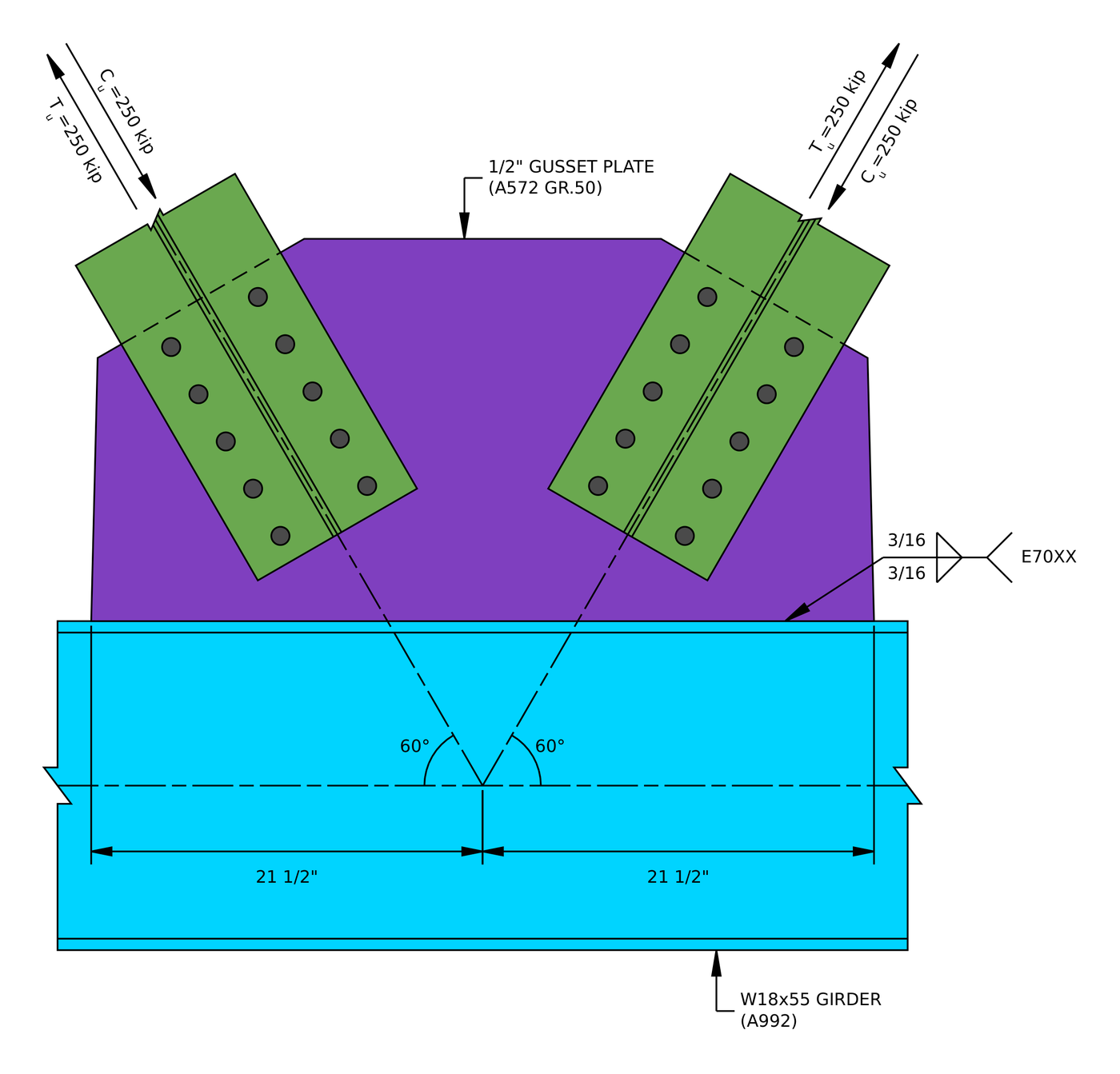
Elevation of the example connection. The brace lines meet on the girder centreline, and the gusset weld runs 21 1/2 in each side of that point.
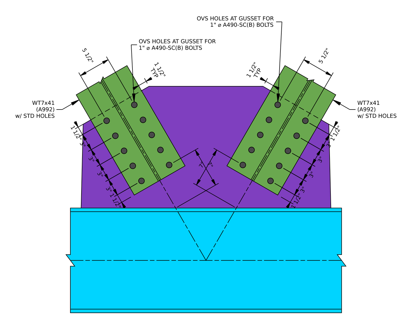
The brace connections. Each WT flange has two lines of five bolts at 3 in on a 5 1/2 in gage, με 1 1/2 in end distances, and the last bolts sit 7 in from the girder.
Chevron brace connection design: the steps at a glance
- Check the detailing limits at the brace bolts: gage, απόσταση και αποστάσεις άκρων.
- Check the slip resistance of the slip-critical bolts.
- Check bolt bearing and tear-out on the gusset plate.
- Check bolt bearing and tear-out on the brace.
- Check block shear of the gusset plate.
- Check block shear of the brace.
- Check the gusset plate in tension on its Whitmore section.
- Check the brace in tension rupture with shear lag.
- Check the gusset plate in compression buckling.
- Check the minimum fillet weld size at the girder.
- Resolve the brace forces at the gusset edge and check the gusset-to-girder weld.
- Check the gusset plate in shear yielding along the girder.
- Check the gusset plate in tension yielding along the girder.
- Check the girder web for local crippling and local yielding.
Design inputs for this example
The design code is AISC 360-16 LRFD. Section properties are from the AISC Manual. The two braces are identical and mirror each other about the work point, so Steps 1 προς το 9 are worked once and apply to both.
| Είδος | Σύμβολο | αξία |
|---|---|---|
| Brace tension load (each brace) | [mathin] T_{u,br} [mathin] | 250 δέρμα μόσχου ακατέργαστου |
| Brace compression load (each brace) | [mathin] C_{u,br} [mathin] | 250 δέρμα μόσχου ακατέργαστου |
| Girder | W18x55, A992 | |
| Girder depth / web thickness | [mathin] d_{g},\ t_{w,g} [mathin] | 18.1 σε / 0.39 σε |
| Girder flange width / πάχος | [mathin] b_{f,g},\ t_{f,g} [mathin] | 7.53 σε / 0.63 σε |
| Girder area / kdes | [mathin] A_{g},\ k_{des,g} [mathin] | 16.2 in² / 1.03 σε |
| Girder yield / εφελκυστική τάση | [mathin] F_{y,g},\ F_{u,g} [mathin] | 50 ksi / 65 ksi |
| Σιδεράκια | WT7x41, A992 | |
| Brace area | [mathin] A_{br} [mathin] | 12 in² |
| Brace flange width / πάχος | [mathin] b_{f,br},\ t_{f,br} [mathin] | 10.1 σε / 0.855 σε |
| Brace stem thickness / κεντροειδές | [mathin] t_{w,br},\ \bar{y} [mathin] | 0.51 σε / 1.39 σε |
| Brace slope from the girder | [mathin] \theta_{br} [mathin] | 60° |
| Brace unbraced length (gusset buckling length) | [mathin] L_{b,br} [mathin] | 7 σε |
| Brace yield / εφελκυστική τάση | [mathin] F_{y,br},\ F_{u,br} [mathin] | 50 ksi / 65 ksi |
| Modulus of elasticity | [mathin] E [mathin] | 29000 ksi |
| Είδος | Σύμβολο | αξία |
|---|---|---|
| Πλάκα | 1/2 σε, A572 Grade 50 | |
| Gusset thickness | [mathin] t_{gp} [mathin] | 0.5 σε |
| Gusset yield / εφελκυστική τάση | [mathin] F_{y,gp},\ F_{u,gp} [mathin] | 50 ksi / 65 ksi |
| Μπουλόνια | 1 in A490-SC, Class B surface | |
| Διάμετρος μπουλονιού | [mathin] d_{b} [mathin] | 1 σε |
| Holes in brace / gusset | Πρότυπο (ΣΜΝ) / oversized (OVS) | |
| Bolt gage across the stem | [mathin] g_{a} [mathin] | 5.5 σε |
| Bolt rows / row spacing | [mathin] n_{r},\ s_{r} [mathin] | 5 / 3 σε |
| Bolt lines (στήλες) | [mathin] n_{c} [mathin] | 2 |
| End distance on brace and gusset | [mathin] L_{ev} [mathin] | 1.5 σε |
| Weld at the girder | 3/16 in fillet, both sides of the gusset, Ε70ΧΧ | |
| Μέγεθος συγκόλλησης / filler strength | [mathin] W,\ F_{EXX} [mathin] | 0.1875 σε / 70 ksi |
| Weld length each side of the work point | [mathin] L_{w1},\ L_{w2} [mathin] | 21.5 σε / 21.5 σε |
| Total gusset length along the girder | [mathin] L_{WT} [mathin] | 43 σε |
Each brace has ten bolts: two lines of five, one line on each side of the stem. The brace length on the gusset adds up from the drawing: δύο 1.5 in end distances plus four 3 in spaces, 15 σε. The inputs page also lists a 3 in bolt column spacing for the left brace and none for the right. It only enters the block shear equations multiplied by [mathin] (n_{c} – 2) = 0 [mathin], so it has no effect.
Βήμα 1: Detailing limits at the brace bolts (AISC 360-16 J3.3, J3.4, J3.5)
The bolt layout has to be buildable and match the assumptions behind the strength equations. Bolts that are too close tear between the holes, edges that are too close tear out, and the gage across the stem has to leave room to fit and tighten the bolts on each side of it.
Για ένα 1 in bolt the minimum spacing is [mathin] 2\tfrac{2}{3} d_{b} = 2.667\,in [mathin] (J3.3) and the minimum edge distance is 1.25 σε (Table J3.4). The WT has standard holes, Έτσι 1.25 in applies to it directly. The gusset has oversized holes, so the Table J3.5 increment of 1/8 in raises its minimum end distance to 1.375 σε.
| Detailing limit | Limit (σε) | Πραγματικός (σε) | DCR | Αποτέλεσμα |
|---|---|---|---|---|
| Minimum bolt gage | 4.175 | 5.500 | 0.759 | cdot K_a |
| Minimum bolt row spacing | 2.667 | 3.000 | 0.889 | cdot K_a |
| Maximum bolt row spacing | 6.000 | 3.000 | 0.500 | cdot K_a |
| Gusset plate minimum vertical edge distance | 1.375 | 1.500 | 0.917 | cdot K_a |
| Brace minimum vertical edge distance | 1.250 | 1.500 | 0.833 | cdot K_a |
| Brace minimum horizontal edge distance | 1.250 | 2.313 | 0.540 | cdot K_a |
The horizontal edge distance on the WT flange is half of what is left after the gage. Using the flange width as a fraction, 10 1/8 σε, αυτό είναι (10.125 - 5.5)/2 = 2.3125 σε. For a minimum limit the ratio is limit over actual, and for a maximum it is actual over limit. The governing row is the gusset end distance with its oversized hole increment:
[math] DCR = \frac{d}{c} = \frac{(1.375)}{(1.5)} = 0.91667 [math]
DCR = 0.917 < 1.0, Εντάξει
Βήμα 2: Slip resistance of the bolts (AISC 360-16 J3.8)
The gusset has oversized holes, και AISC 360-16 J3.2 allows oversized holes only in slip-critical joints. So the bolts are pretensioned and the brace force is carried by friction between the WT flange and the gusset. The check is that the joint does not slip under the factored load.
Οπου [mathin] \phi = 0.85 [mathin] for oversized holes, [mathin] \mu = 0.5 [mathin] for a Class B surface, [mathin] D_{u} = 1.13 [mathin], [mathin] h_{f} = 1 [mathin] because there are no fillers, [mathin] T_{b} = 64\,kip [mathin] for a 1 in A490 bolt (Table J3.1), [mathin] N_{s} = 1 [mathin] slip plane, [mathin] n_{r} = 5 [mathin] και [mathin] n_{c} = 2 [mathin]:
[math] \phi R_{n} = \phi\, \mu\, D_{u}\, h_{f}\, T_{b}\, N_{s}\, n_{r}\, n_{c} [math]
[math] \phi R_{n} = (0.85) \times (0.5) \times (1.13) \times (1) \times (64\,kip) \times (1) \times (5) \times (2) [math]
[math] \phi R_{n} = 307.36\,kip [math]
DCR = 250 δέρμα μόσχου ακατέργαστου / 307.36 kip = 0.813 < 1.0, Εντάξει
The same check covers tension and compression, because the brace force is 250 kip either way.
Βήμα 3: Bolt bearing and tear-out on the gusset plate (AISC 360-16 J3.10)
Slip-critical bolts still have to be checked for bearing, because if the joint does slip the bolts end up bearing on the sides of their holes. In tension the brace pulls the bolts away from the girder, so they bear on the gusset toward its outer edge. The bolt nearest that edge has the least material in front of it.
The gusset hole is oversized, [mathin] d_{h} = 1.25\,in [mathin]. Clear distance for the end bolt, με [mathin] L_{ev} = 1.5\,in [mathin]:
[math] l_{c1} = L_{ev} – \frac{d_{h}}{2} = (1.5\,in) – \frac{(1.25\,in)}{2} = 0.875\,in [math]
Clear distance between bolts, με [mathin] s_{r} = 3\,in [mathin]:
[math] l_{c2} = s_{r} – d_{h} = (3\,in) – (1.25\,in) = 1.75\,in [math]
Οπου [mathin] t_{gp} = 0.5\,in [mathin], [mathin] F_{u,gp} = 65\,ksi [mathin], [mathin] n_{r} = 5 [mathin], [mathin] n_{c} = 2 [mathin], [mathin] d_{b} = 1\,in [mathin] και [mathin] \phi = 0.75 [mathin]:
[math] \phi R_{n,tearout} = \phi \left[ \min\left(1.2\, l_{c1},\, 2.4\, d_{b}\right) t_{gp} F_{u,gp}\, n_{c} + \min\left(1.2\, l_{c2},\, 2.4\, d_{b}\right) t_{gp} F_{u,gp}\, n_{c} \left( n_{r} – 1 \right) \right] [math]
[math] \phi R_{n,tearout} = (0.75) \times \left[ \min\left(1.2 \times (0.875\,in),\, 2.4 \times (1\,in)\right) \times (0.5\,in) \times (65\,ksi) \times (2) + \min\left(1.2 \times (1.75\,in),\, 2.4 \times (1\,in)\right) \times (0.5\,in) \times (65\,ksi) \times (2) \times ((5) – 1) \right] [math]
[math] \phi R_{n,tearout} = 460.69\,kip [math]
DCR = 250 δέρμα μόσχου ακατέργαστου / 460.69 kip = 0.543 < 1.0, Εντάξει
Tear-out governs every bolt, because the oversized hole eats into the clear distance: 1.2 lc is below 2.4 db for both the end bolts and the inner bolts. In compression the bolts bear toward the girder instead, where there is more gusset, so tension is the case that matters.
Βήμα 4: Bolt bearing and tear-out on the brace (AISC 360-16 J3.10)
The same check applies to the WT flange. In tension the brace is pulled away from the girder, so its bolts bear toward the end of the WT nearest the girder.
The WT has standard holes, [mathin] d_{h} = 1.125\,in [mathin]:
[math] l_{c1} = L_{ev} – \frac{d_{h}}{2} = (1.5\,in) – \frac{(1.125\,in)}{2} = 0.9375\,in [math]
[math] l_{c2} = s_{r} – d_{h} = (3\,in) – (1.125\,in) = 1.875\,in [math]
Οπου [mathin] t_{f,br} = 0.855\,in [mathin] και [mathin] F_{u,br} = 65\,ksi [mathin]:
[math] \phi R_{n,tearout} = \phi \left[ \min\left(1.2\, l_{c1},\, 2.4\, d_{b}\right) t_{f,br} F_{u,br}\, n_{c} + \min\left(1.2\, l_{c2},\, 2.4\, d_{b}\right) t_{f,br} F_{u,br}\, n_{c} \left( n_{r} – 1 \right) \right] [math]
[math] \phi R_{n,tearout} = (0.75) \times \left[ \min\left(1.2 \times (0.9375\,in),\, 2.4 \times (1\,in)\right) \times (0.855\,in) \times (65\,ksi) \times (2) + \min\left(1.2 \times (1.875\,in),\, 2.4 \times (1\,in)\right) \times (0.855\,in) \times (65\,ksi) \times (2) \times ((5) – 1) \right] [math]
[math] \phi R_{n,tearout} = 844.05\,kip [math]
DCR = 250 δέρμα μόσχου ακατέργαστου / 844.05 kip = 0.296 < 1.0, Εντάξει
ο 0.855 in WT flange is 1.7 times as thick as the gusset, and the smaller standard hole leaves more clear distance, so the brace has nearly twice the bearing strength of the gusset.
Βήμα 5: Block shear of the gusset plate (AISC 360-16 J4.3)
A block of the gusset can tear out around the bolts: shear along the bolt lines to the gusset’s edge, plus tension across the bolt group. With two bolt lines there are two shapes to check. The L pattern shears along one bolt line and tears across both lines to the gusset’s side edge. The U pattern shears along both bolt lines and tears across between them. The weaker of the two governs.
L pattern
Net area in tension, across the 5.5 in gage plus the gusset edge distance beyond the far bolt line, [mathin] L_{eh,gp} = 2.3\,in [mathin]. That edge distance is the same as the WT’s own edge distance, (10.1 - 5.5)/2. The tension path crosses one full hole and one half hole, and each hole adds 1/16 in for damage during punching (B4.3):
[math] A_{nt} = t_{gp} \left[ (n_{c}-2)\, s_{c} + g_{a} + L_{eh,gp} – (n_{c} – 0.5) \left( d_{h} + 0.0625\,in \right) \right] [math]
[math] A_{nt} = (0.5\,in) \times \left[ ((2)-2) \times (3\,in) + (5.5\,in) + (2.3\,in) – ((2) – 0.5) \times ((1.25\,in) + (0.0625\,in)) \right] = 2.9156\,in^{2} [math]
Gross area in shear, along one bolt line from the gusset’s edge to the farthest bolt:
[math] A_{gv} = t_{gp} \left[ L_{ev} + (n_{r}-1)\, s_{r} \right] = (0.5\,in) \times \left[ (1.5\,in) + ((5)-1) \times (3\,in) \right] = 6.75\,in^{2} [math]
Net area in shear. The report writes the shear length as the 15 in brace length on the gusset, [mathin] L_{br,gp} [mathin], less one end distance, which is the same 13.5 in as in the gross area:
[math] A_{nv} = t_{gp} \left[ L_{br,gp} – L_{ev} – (n_{r} – 0.5)\left( d_{h} + 0.0625\,in \right) \right] [math]
[math] A_{nv} = (0.5\,in) \times \left[ (15\,in) – (1.5\,in) – ((5) – 0.5) \times ((1.25\,in) + (0.0625\,in)) \right] = 3.7969\,in^{2} [math]
Block shear strength, με [mathin] U_{bs} = 1 [mathin] because the tension stress is uniform, [mathin] F_{u,gp} = 65\,ksi [mathin], [mathin] F_{y,gp} = 50\,ksi [mathin] και [mathin] \phi = 0.75 [mathin]:
[math] \phi R_{n} = \phi \left( 0.6\, F_{u,gp} A_{nv} + U_{bs} F_{u,gp} A_{nt} \le 0.6\, F_{y,gp} A_{gv} + U_{bs} F_{u,gp} A_{nt} \right) [math]
[math] \phi R_{n} = (0.75) \times \left( 0.6 \times (65\,ksi) \times (3.7969\,in^{2}) + (1) \times (65\,ksi) \times (2.9156\,in^{2}) \le 0.6 \times (50\,ksi) \times (6.75\,in^{2}) + (1) \times (65\,ksi) \times (2.9156\,in^{2}) \right) [math]
[math] \phi R_{n} = 253.2\,kip [math]
U pattern
Net area in tension, between the two bolt lines only, which crosses one hole in total (a half hole at each line):
[math] A_{nt} = t_{gp} \left[ (n_{c}-2)\, s_{c} + g_{a} – (n_{c} – 1) \left( d_{h} + 0.0625\,in \right) \right] [math]
[math] A_{nt} = (0.5\,in) \times \left[ ((2)-2) \times (3\,in) + (5.5\,in) – ((2) – 1) \times ((1.25\,in) + (0.0625\,in)) \right] = 2.0937\,in^{2} [math]
Gross and net areas in shear, now along both bolt lines:
[math] A_{gv} = 2\, t_{gp} \left[ L_{ev} + (n_{r}-1)\, s_{r} \right] = 2 \times (0.5\,in) \times \left[ (1.5\,in) + ((5)-1) \times (3\,in) \right] = 13.5\,in^{2} [math]
[math] A_{nv} = 2\, t_{gp} \left[ (n_{r}-1)\, s_{r} + L_{ev} – (n_{r} – 0.5)\left( d_{h} + 0.0625\,in \right) \right] [math]
[math] A_{nv} = 2 \times (0.5\,in) \times \left[ ((5)-1) \times (3\,in) + (1.5\,in) – ((5) – 0.5) \times ((1.25\,in) + (0.0625\,in)) \right] = 7.5937\,in^{2} [math]
[math] \phi R_{n} = (0.75) \times \left( 0.6 \times (65\,ksi) \times (7.5937\,in^{2}) + (1) \times (65\,ksi) \times (2.0937\,in^{2}) \le 0.6 \times (50\,ksi) \times (13.5\,in^{2}) + (1) \times (65\,ksi) \times (2.0937\,in^{2}) \right) [math]
[math] \phi R_{n} = 324.19\,kip [math]
Governing block shear
[math] \phi R_{n} = \min\left( \phi R_{n},\, \phi R_{n} \right) = \min\left( (253.2\,kip),\, (324.19\,kip) \right) = 253.2\,kip [math]
DCR = 250 δέρμα μόσχου ακατέργαστου / 253.2 kip = 0.987 < 1.0, Εντάξει
This is the closest check on the brace side. The L pattern governs because it has only one shear plane, and net shear rupture governs within it: ο 1 1/4 in oversized holes take 5.9 in out of the 13.5 in shear length.
Βήμα 6: Block shear of the brace (AISC 360-16 J4.3)
The WT flange can tear out too. Here the blocks are on the outside: each bolt line shears along its length to the end of the WT, and tears across to the flange tip beside it. Two L-shaped blocks fail together, one each side of the stem.
Net area in tension, from each bolt line out to the flange tip, with the flange width less the gage and one hole in total, [mathin] d_{h} = 1.125\,in [mathin]:
[math] A_{nt} = t_{f,br} \left[ b_{f,br} – g_{a} – (n_{c} – 1) \left( d_{h} + 0.0625\,in \right) \right] [math]
[math] A_{nt} = (0.855\,in) \times \left[ (10.1\,in) – (5.5\,in) – ((2) – 1) \times ((1.125\,in) + (0.0625\,in)) \right] = 2.9177\,in^{2} [math]
[math] A_{gv} = 2\, t_{f,br} \left[ L_{ev} + (n_{r}-1)\, s_{r} \right] = 2 \times (0.855\,in) \times \left[ (1.5\,in) + ((5)-1) \times (3\,in) \right] = 23.085\,in^{2} [math]
[math] A_{nv} = 2\, t_{f,br} \left( L_{ev} + (n_{r}-1)\, s_{r} – (n_{r} – 0.5)\left( d_{h} + 0.0625\,in \right) \right) [math]
[math] A_{nv} = 2 \times (0.855\,in) \times \left( (1.5\,in) + ((5)-1) \times (3\,in) – ((5) – 0.5) \times ((1.125\,in) + (0.0625\,in)) \right) = 13.947\,in^{2} [math]
Με [mathin] F_{u,br} = 65\,ksi [mathin], [mathin] F_{y,br} = 50\,ksi [mathin], [mathin] U_{bs} = 1 [mathin] και [mathin] \phi = 0.75 [mathin]:
[math] \phi R_{n} = \phi \left( 0.6\, F_{u,br} A_{nv} + U_{bs} F_{u,br} A_{nt} \le 0.6\, F_{y,br} A_{gv} + U_{bs} F_{u,br} A_{nt} \right) [math]
[math] \phi R_{n} = (0.75) \times \left( 0.6 \times (65\,ksi) \times (13.947\,in^{2}) + (1) \times (65\,ksi) \times (2.9177\,in^{2}) \le 0.6 \times (50\,ksi) \times (23.085\,in^{2}) + (1) \times (65\,ksi) \times (2.9177\,in^{2}) \right) [math]
[math] \phi R_{n} = 550.19\,kip [math]
DCR = 250 δέρμα μόσχου ακατέργαστου / 550.19 kip = 0.454 < 1.0, Εντάξει
Βήμα 7: Gusset plate in tension on the Whitmore section (AISC 360-16 J4.1)
The brace force enters the gusset through the bolts and spreads out as it travels along the plate. The Whitmore section is the effective width that takes that force at the last bolt row: lines drawn at 30° from the outer bolts of the first row, measured across the last row (AISC Manual Part 9, Σύκο. 9-1). The gusset must not yield on that width, and it must not rupture on that width less the holes.
Whitmore πλάτος
The bolt group is [mathin] L_{br} = (n_{r}-1)\, s_{r} = 12\,in [mathin] μακρύς, and its two lines are [mathin] W_{br} = g_{a} = 5.5\,in [mathin] apart. In the report, [mathin] W [mathin] in this step is the Whitmore width, not the weld size:
[math] W = 2\, L_{br} \tan(\theta) + W_{br} = 2 \times (12\,in) \times \tan((30)) + (5.5\,in) = 19.356\,in [math]
The gusset here is large enough to take the full 30° spread on both sides, so no part of the Whitmore width runs off the plate.
Tension yielding (Εξ. J4-1)
Με [mathin] \phi = 0.9 [mathin], [mathin] F_{y,gp} = 50\,ksi [mathin] και [mathin] t_{gp} = 0.5\,in [mathin]:
[math] \phi R_{n,ty} = \phi\, F_{y,gp}\, t_{gp}\, W = (0.9) \times (50\,ksi) \times (0.5\,in) \times (19.356\,in) = 435.52\,kip [math]
Tension rupture (Εξ. J4-2)
The net width removes the two oversized holes in the last row, [mathin] d_{h} = 1.25\,in [mathin], με [mathin] \phi = 0.75 [mathin] και [mathin] F_{u,gp} = 65\,ksi [mathin]:
[math] \phi R_{n,tr} = \phi\, F_{u,gp}\, t_{gp} \left[ W – n_{c}\left( d_{h} + 0.0625\,in \right) \right] [math]
[math] \phi R_{n,tr} = (0.75) \times (65\,ksi) \times (0.5\,in) \times \left[ (19.356\,in) – (2) \times ((1.25\,in) + (0.0625\,in)) \right] = 407.83\,kip [math]
[math] \phi R_{n} = \min\left( \phi R_{n,ty},\, \phi R_{n,tr} \right) = \min\left( (435.52\,kip),\, (407.83\,kip) \right) = 407.83\,kip [math]
DCR = 250 δέρμα μόσχου ακατέργαστου / 407.83 kip = 0.613 < 1.0, Εντάξει
Βήμα 8: Brace in tension rupture with shear lag (AISC 360-16 D3, J4.1)
Only the flange of the WT is bolted, so the force in the stem has to flow into the flange near the connection. That uneven stress is shear lag, and AISC handles it with the factor U, which reduces the net area.
From Table D3.1, Υπόθεση 2, with the WT’s centroid [mathin] \bar{y} = 1.39\,in [mathin] measured from the bolted face of the flange and the connection length [mathin] (n_{r} – 1)\, s_{r} = 12\,in [mathin]:
[math] U = 1 – \frac{\bar{y}}{(n_{r} – 1)\, s_{r}} = 1 – \frac{(1.39\,in)}{((5) – 1) \times (3\,in)} = 0.88421 [math]
The net area removes the two holes in one row from the flange. Οπου [mathin] A_{br} = 12\,in^{2} [mathin], [mathin] d_{h} = 1.125\,in [mathin], [mathin] t_{f,br} = 0.855\,in [mathin], [mathin] F_{u,br} = 65\,ksi [mathin] και [mathin] \phi = 0.75 [mathin]:
[math] \phi R_{n,tr} = \phi\, F_{u,br}\, U \left[ A_{br} – n_{c}\left( d_{h} + 0.0625\,in \right) t_{f,br} \right] [math]
[math] \phi R_{n,tr} = (0.75) \times (65\,ksi) \times (0.88421) \times \left[ (12\,in^{2}) – (2) \times ((1.125\,in) + (0.0625\,in)) \times (0.855\,in) \right] = 429.73\,kip [math]
DCR = 250 δέρμα μόσχου ακατέργαστου / 429.73 kip = 0.582 < 1.0, Εντάξει
The long bolt group keeps U high. Gross yielding of the brace is part of the member design, so it is not repeated here.
Βήμα 9: Gusset plate in compression buckling (AISC 360-16 J4.4, Ε3)
When a brace is in compression it pushes the gusset toward the girder. The strip of gusset between the last bolt row and the girder flange can buckle out of plane, so it is checked as a column with the Whitmore width as its cross section.
The buckling length is the 7 in shown on the drawing, from the bolt row nearest the girder to the girder flange, measured along the brace. The report labels it the brace unbraced length, [mathin] L_{b,br} = 7\,in [mathin]. The gusset is welded to the girder on one edge only and its free end can sway out of plane with the braces, so the report takes [mathin] K = 1.2 [mathin]. For a solid rectangle, [mathin] r = t_{gp}/\sqrt{12} = 0.14434\,in [mathin]:
[math] \frac{KL}{r} = \frac{(1.2) \times (7\,in)}{(0.5\,in)/\sqrt{12}} = 58.197 [math]
Από [mathin] KL/r \gt 25 [mathin], J4.4 sends the check to Chapter E. Elastic buckling stress:
[math] F_{e} = \frac{\pi^{2} E}{\left( \frac{KL}{r} \right)^{2}} = \frac{\pi^{2} \times (29000\,ksi)}{((58.197))^{2}} = 84.508\,ksi [math]
[math] 4.71 \sqrt{\frac{E}{F_{y}}} = 113.43 [math]
Από [mathin] KL/r \le 4.71\sqrt{E/F_{y}} [mathin], the inelastic equation E3-2 applies:
[math] F_{cr} = \left( 0.658^{\frac{F_{y,gp}}{F_{e}}} \right) F_{y,gp} = \left( 0.658^{\frac{(50\,ksi)}{(84.508\,ksi)}} \right) \times (50\,ksi) = 39.032\,ksi [math]
Με [mathin] \phi = 0.9 [mathin] and the Whitmore width [mathin] W = 19.356\,in [mathin]:
[math] \phi R_{n} = \phi\, F_{cr}\, t_{gp}\, W = (0.9) \times (39.032\,ksi) \times (0.5\,in) \times (19.356\,in) = 339.98\,kip [math]
DCR = 250 δέρμα μόσχου ακατέργαστου / 339.98 kip = 0.735 < 1.0, Εντάξει
Slenderness costs about 22% of the yield stress here. Moving the bolts closer to the girder shortens L, and a thicker gusset raises r directly.
Βήμα 10: Minimum fillet weld size at the girder (AISC 360-16 J2.2b)
A fillet weld that is too small for the parts it joins can crack as it cools, because the thicker part draws heat out of it too fast. Table J2.4 sets the minimum by the thinner part joined. Here that is the 1/2 in gusset, which falls in the over 1/4 σε 1/2 in band, so the minimum is 3/16 σε.
| Detailing limit | Limit (σε) | Πραγματικός (σε) | DCR | Αποτέλεσμα |
|---|---|---|---|---|
| Minimum fillet weld size | 0.188 | 0.188 | 1.000 | cdot K_a |
[math] DCR = \frac{d}{c} = \frac{(0.188)}{(0.188)} = 1 [math]
DCR = 1.000, Εντάξει
A ratio of 1.000 here only says the 3/16 in weld is exactly the smallest size allowed. Whether it is strong enough is the next step.
Βήμα 11: Gusset-to-girder weld (AISC 360-16 J2.4, Οδηγός σχεδίασης AISC 29)
The gusset is welded to the girder flange with a 3/16 in fillet on each side. The two brace forces reach the gusset edge as a normal force, a shear along the girder and a moment, and the weld carries all three together. This step resolves the brace forces at the gusset edge, finds the worst load on the weld, and checks the weld against it.
Base metal limit on weld size (AISC Manual Eq. 9-2)
The gusset has a weld on both faces, so half its thickness backs each weld. Με [mathin] t_{f,g} = 0.63\,in [mathin], [mathin] F_{u,g} = 65\,ksi [mathin], [mathin] t_{gp} = 0.5\,in [mathin] και [mathin] F_{u,gp} = 65\,ksi [mathin]:
[math] D_{max} = \frac{t_{f,g} F_{u,g} \le \frac{t_{gp}}{2} F_{u,gp}}{3.09\,kip/in \times F_{EXX}/F_{E70XX}} = \frac{(0.63\,in) \times (65\,ksi) \le (0.25\,in) \times (65\,ksi)}{(3.09\,kip/in) \times (1)} = 5.2589 [math]
Αυτό είναι 5.2589 sixteenths, σχετικά με 0.329 σε, so the full 3/16 in weld counts.
Effective weld length
The gusset runs [mathin] L_{WT} = 43\,in [mathin] along the girder. Each of the two weld lines is reduced by 2W for the ends:
[math] L_{w} = 2 \left[ L_{WT} – 2W \right] = 2 \times \left[ (43\,in) – 2 \times (0.1875\,in) \right] = 85.25\,in [math]
Forces at the gusset edge
Each brace force splits into a component perpendicular to the girder, [mathin] P \sin\theta [mathin], and one along it, [mathin] P \cos\theta [mathin]. The report takes the normal force as the largest that any one brace delivers, τάση ή συμπίεση:
[math] N_{br} = \max\left[ T_{u,l,br} \sin(\theta_{l,br}),\, C_{u,l,br} \sin(\theta_{l,br}),\, T_{u,r,br} \sin(\theta_{r,br}),\, C_{u,r,br} \sin(\theta_{r,br}) \right] = (250\,kip) \times \sin((60)) = 216.51\,kip [math]
The shear along the girder is the sum of the two horizontal components with one brace in tension and the other in compression, which is the usual lateral load case for a chevron. Both components then point the same way:
[math] V_{br} = \max\left[ T_{u,l,br} \cos(\theta_{l,br}) + C_{u,r,br} \cos(\theta_{r,br}),\, C_{u,l,br} \cos(\theta_{l,br}) + T_{u,r,br} \cos(\theta_{r,br}) \right] [math]
[math] V_{br} = (250\,kip) \times \cos((60)) + (250\,kip) \times \cos((60)) = 250\,kip [math]
In that tension and compression case the two vertical components cancel. Pairing the 250 kip shear with a full 216.51 kip normal force from one brace is an envelope that covers unequal brace forces as well.
The moment has two parts, following AISC Design Guide 29, Παράδειγμα 5.9. The first is the normal force times its offset from the middle of the weld, which is zero here because the gusset runs 21.5 in each side of the work point. The second comes from the shear. The horizontal brace forces meet at the work point on the girder centreline, [mathin] d_{g}/2 = 9.05\,in [mathin] below the gusset edge, so moving them up to the edge adds [mathin] V_{br}\, d_{g}/2 [mathin]:
[math] M_{br} = \frac{N_{br} \left| L_{w1} – L_{w2} \right|}{2} + \frac{V_{br}\, d_{g}}{2} = \frac{(216.51\,kip) \times |(21.5\,in) – (21.5\,in)|}{2} + \frac{(250\,kip) \times (18.1\,in)}{2} = 188.54\,kip{\cdot}ft [math]
Αυτό είναι 2262.5 κοτόπουλο. The moment adds to the normal force at one end of the weld and subtracts at the other. The report turns the moment into an equivalent normal force using the plastic section modulus of the two weld lines, [mathin] L_{w}^{2}/8 [mathin], which gives the peak normal load:
[math] N_{br,T} = \frac{8\, M_{br}}{L_{w}} + N_{br} = \frac{8 \times (188.54\,kip{\cdot}ft)}{(85.25\,in)} + (216.51\,kip) = 428.82\,kip [math]
The moment is converted to kip-in (× 12) inside that fraction. The resultant at the peak and its angle to the weld axis:
[math] R = \sqrt{\left( N_{br,T} \right)^{2} + \left( V_{br} \right)^{2}} = \sqrt{((428.82\,kip))^{2} + ((250\,kip))^{2}} = 496.38\,kip [math]
[math] \theta = \tan^{-1}\left| \frac{N_{br,T}}{V_{br}} \right| = \tan^{-1}\left| \frac{(428.82\,kip)}{(250\,kip)} \right| = 59.758 [math]
Weld ductility factor
The load on the weld is not even. It peaks at one end and falls almost to nothing at the other. Fillet welds have limited ductility, so AISC Design Guide 29 and AISC Manual Part 13 design a gusset edge weld for the larger of the peak load and 1.25 times the average of the peak and minimum loads. ο 1.25 lets the weld redistribute load before it fractures.
At the low-stress end the bending subtracts from the normal force:
[math] N_{br,min} = \left| N_{br} – \frac{8\, M_{br}}{L_{w}} \right| = \left| (216.51\,kip) – \frac{8 \times (188.54\,kip{\cdot}ft)}{(85.25\,in)} \right| = 4.1896\,kip [math]
[math] R_{min} = \sqrt{\left( N_{br,min} \right)^{2} + \left( V_{br} \right)^{2}} = \sqrt{((4.1896\,kip))^{2} + ((250\,kip))^{2}} = 250.04\,kip [math]
[math] R_{w} = \max\left( R,\, 1.25\, \frac{R + R_{min}}{2} \right) = \max\left( (496.38\,kip),\, 1.25 \times \frac{(496.38\,kip) + (250.04\,kip)}{2} \right) = 496.38\,kip [math]
The averaged value is 466.51 δέρμα μόσχου ακατέργαστου, so the peak governs.
Αντοχή συγκόλλησης (Εξ. J2-4)
The resultant is at 59.758° to the weld, so the directional factor [mathin] 1 + 0.5 \sin^{1.5}\theta [mathin] adds about 40% to the strength. Με [mathin] \phi = 0.75 [mathin] και [mathin] F_{EXX} = 70\,ksi [mathin]:
[math] \phi R_{n} = \phi\, 0.6\, F_{EXX} \frac{\sqrt{2}}{2} \left( W \le \frac{D_{max}}{16} \right) \left[ 1 + 0.5 \left( \sin\theta \right)^{1.5} \right] L_{w} [math]
[math] \phi R_{n} = (0.75) \times 0.6 \times (70\,ksi) \times \frac{\sqrt{2}}{2} \times \left( (0.1875\,in) \le \frac{(5.2589)}{(16)} \right) \times \left[ 1 + 0.5 \times (\sin(59.758))^{1.5} \right] \times (85.25\,in) [math]
[math] \phi R_{n} = 498.98\,kip [math]
DCR = 496.38 δέρμα μόσχου ακατέργαστου / 498.98 kip = 0.995 < 1.0, Εντάξει
This is the governing check of the whole connection. Almost half of the peak normal load, 212.31 δέρμα μόσχου ακατέργαστου, comes from the moment, and that moment exists only because the work point is 9.05 in below the weld. The base metal would allow a weld up to about 5/16 σε, so a 1/4 in fillet is the simplest way to gain margin.
Βήμα 12: Gusset plate in shear yielding along the girder (AISC 360-16 J4.2)
The horizontal force, [mathin] V_{br} = 250\,kip [mathin], passes through the gusset’s welded edge as shear. The gross section along that edge must not yield.
Με [mathin] L_{WT} = 43\,in [mathin], [mathin] t_{gp} = 0.5\,in [mathin], [mathin] F_{y,gp} = 50\,ksi [mathin] και [mathin] \phi = 1 [mathin]:
[math] A_{gv} = L_{WT}\, t_{gp} = (43\,in) \times (0.5\,in) = 21.5\,in^{2} [math]
[math] \phi R_{n,sy} = \phi\, 0.6\, F_{y,gp} A_{gv} = (1) \times 0.6 \times (50\,ksi) \times (21.5\,in^{2}) = 645\,kip [math]
DCR = 250 δέρμα μόσχου ακατέργαστου / 645 kip = 0.388 < 1.0, Εντάξει
Βήμα 13: Gusset plate in tension yielding along the girder (AISC 360-16 J4.1)
The normal force and the moment put the gusset’s welded edge in tension, highest at one end. Following AISC Design Guide 29, Παράδειγμα 5.3, the report adds the two as normal stresses on the edge and turns the peak back into an equivalent force over the full edge.
The normal stress is [mathin] N/(t\,l) + M/(t\,l^{2}/4) [mathin]. Multiplying by [mathin] t\,l [mathin], με [mathin] l = L_{WT} = 43\,in [mathin]:
[math] N_{e} = \left| N_{br} \right| + \frac{4 \left| M_{br} \right|}{L_{WT}} = |(216.51\,kip)| + \frac{4 \times |(188.54\,kip{\cdot}ft)|}{(43\,in)} = 426.97\,kip [math]
This is slightly below the weld’s 428.82 kip because it uses the 43 in gusset edge rather than the 85.25 in of effective weld split over two lines. Με [mathin] \phi = 0.9 [mathin]:
[math] \phi R_{n,ty} = \phi\, F_{y,gp}\, t_{gp}\, L_{WT} = (0.9) \times (50\,ksi) \times (0.5\,in) \times (43\,in) = 967.5\,kip [math]
DCR = 426.97 δέρμα μόσχου ακατέργαστου / 967.5 kip = 0.441 < 1.0, Εντάξει
Βήμα 14: Girder web local crippling and local yielding (AISC 360-16 J10.3, J10.2)
The gusset delivers a concentrated force to the girder flange over its 43 in length. When the braces push up on the girder, the girder web above the gusset can yield locally or crumple (cripple). The demand is the peak normal load from Step 11, [mathin] N_{br,T} = 428.82\,kip [mathin].
Web local crippling (Εξ. J10-4)
Με [mathin] \phi = 0.75 [mathin], [mathin] t_{w,g} = 0.39\,in [mathin], bearing length [mathin] L_{WT} = 43\,in [mathin], [mathin] d_{g} = 18.1\,in [mathin], [mathin] t_{f,g} = 0.63\,in [mathin], [mathin] F_{y,g} = 50\,ksi [mathin] και [mathin] Q_{f} = 1 [mathin]:
[math] \phi R_{n,wlc} = \phi\, 0.8 \left( t_{w,g} \right)^{2} \left[ 1 + 3 \left( \frac{L_{WT}}{d_{g}} \right) \left( \frac{t_{w,g}}{t_{f,g}} \right)^{1.5} \right] \sqrt{\frac{E\, F_{y,g}\, t_{f,g}}{t_{w,g}}}\, Q_{f} [math]
[math] \phi R_{n,wlc} = (0.75) \times 0.8 \times ((0.39\,in))^{2} \times \left[ 1 + 3 \times \left( \frac{(43\,in)}{(18.1\,in)} \right) \times \left( \frac{(0.39\,in)}{(0.63\,in)} \right)^{1.5} \right] \times \sqrt{\frac{(29000\,ksi) \times (50\,ksi) \times (0.63\,in)}{(0.39\,in)}} \times (1) [math]
[math] \phi R_{n,wlc} = 624.51\,kip [math]
Web local yielding (Εξ. J10-2)
The force spreads through the flange and fillet on a 2.5:1 slope on each side, so the web yields over [mathin] 5k + l_{b} [mathin]. Με [mathin] \phi = 1 [mathin] και [mathin] k_{des,g} = 1.03\,in [mathin]:
[math] \phi R_{n,wly} = \phi\, F_{y,g}\, t_{w,g} \left( 5\, k_{des,g} + L_{WT} \right) = (1) \times (50\,ksi) \times (0.39\,in) \times \left( 5 \times (1.03\,in) + (43\,in) \right) = 938.92\,kip [math]
[math] \phi R_{n} = \min\left( \phi R_{n,wlc},\, \phi R_{n,wly} \right) = \min\left( (624.51\,kip),\, (938.92\,kip) \right) = 624.51\,kip [math]
DCR = 428.82 δέρμα μόσχου ακατέργαστου / 624.51 kip = 0.687 < 1.0, Εντάξει
The W18x55 has a thin 0.39 in web, so crippling governs by a wide margin. ο 43 in gusset spreads the force well enough that no stiffener is needed.
Summary of checks
The brace-side checks are the same for the left and right braces.
| Design check | Ζήτηση | Χωρητικότητα | DCR | Αποτέλεσμα |
|---|---|---|---|---|
| Detailing limits at the brace bolts | 1.375 σε | 1.500 σε | 0.917 | cdot K_a |
| Bolts in shear (slip-critical) | 250.000 δέρμα μόσχου ακατέργαστου | 307.360 δέρμα μόσχου ακατέργαστου | 0.813 | cdot K_a |
| Bolt bearing on the gusset plate | 250.000 δέρμα μόσχου ακατέργαστου | 460.688 δέρμα μόσχου ακατέργαστου | 0.543 | cdot K_a |
| Bolt bearing on the brace | 250.000 δέρμα μόσχου ακατέργαστου | 844.045 δέρμα μόσχου ακατέργαστου | 0.296 | cdot K_a |
| Block shear of the gusset plate | 250.000 δέρμα μόσχου ακατέργαστου | 253.195 δέρμα μόσχου ακατέργαστου | 0.987 | cdot K_a |
| Block shear of the brace | 250.000 δέρμα μόσχου ακατέργαστου | 550.193 δέρμα μόσχου ακατέργαστου | 0.454 | cdot K_a |
| Gusset plate in tension | 250.000 δέρμα μόσχου ακατέργαστου | 407.828 δέρμα μόσχου ακατέργαστου | 0.613 | cdot K_a |
| Brace in tension rupture | 250.000 δέρμα μόσχου ακατέργαστου | 429.734 δέρμα μόσχου ακατέργαστου | 0.582 | cdot K_a |
| Gusset plate in compression | 250.000 δέρμα μόσχου ακατέργαστου | 339.984 δέρμα μόσχου ακατέργαστου | 0.735 | cdot K_a |
| Minimum fillet weld size | 0.188 σε | 0.188 σε | 1.000 | cdot K_a |
| Weld at gusset to girder | 496.376 δέρμα μόσχου ακατέργαστου | 498.977 δέρμα μόσχου ακατέργαστου | 0.995 | cdot K_a |
| Gusset shear yielding along the girder | 250.000 δέρμα μόσχου ακατέργαστου | 645.000 δέρμα μόσχου ακατέργαστου | 0.388 | cdot K_a |
| Gusset tension yielding along the girder | 426.971 δέρμα μόσχου ακατέργαστου | 967.500 δέρμα μόσχου ακατέργαστου | 0.441 | cdot K_a |
| Girder web (local crippling governs) | 428.823 δέρμα μόσχου ακατέργαστου | 624.511 δέρμα μόσχου ακατέργαστου | 0.687 | cdot K_a |
The connection passes every check of this chevron brace connection design. The gusset-to-girder weld governs at 0.995, driven by the moment from the work point sitting half the girder depth below the weld. On the brace side, block shear of the gusset is next at 0.987, from the L pattern through the oversized holes. The minimum weld size shows 1.000 only because the weld is exactly the Table J2.4 minimum.
What to change if a check fails
- Weld at the girder: use a larger fillet (the base metal allows up to about 5/16 in here) or make the gusset longer. A longer gusset adds weld length and reduces the 8M/Lw term at the same time.
- Block shear of the gusset: add a bolt row, which lengthens the shear planes, or increase the edge distance from the outer bolt line to the gusset edge. Standard holes instead of oversized holes in the gusset add net area.
- Slip resistance: add bolts, use a larger bolt, or use standard holes in the gusset, which raises φ from 0.85 προς το 1.00.
- Bearing and tear-out: increase the end distance or the bolt spacing, or use a thicker gusset.
- Brace tension rupture: lengthen the bolt group to raise U, or use a heavier WT.
- Gusset tension or compression: a thicker gusset raises both. A longer bolt group widens the Whitmore section, and moving the bolts closer to the girder shortens the buckling length.
- Girder web: lengthen the gusset to spread the force, or add a pair of web stiffeners at the work point.
Συχνές ερωτήσεις
What is a chevron brace?
A chevron brace is a pair of diagonal braces that meet at the middle of a beam, forming an inverted V (or a V when they meet at the beam below). Under lateral load one brace is in tension and the other in compression, and their horizontal components add up at the beam. Because each brace can reverse, this example designs both braces for 250 kip in tension and 250 kip in compression.
Why is there a moment on the gusset weld when the gusset is centred?
The brace lines meet at a work point on the girder centreline, 9.05 in below the gusset edge. The horizontal brace forces act at that point, and moving them up to the weld adds a moment equal to the horizontal force times half the girder depth: 250 kip × 9.05 σε = 2262.5 κοτόπουλο, ή 188.54 kip-ft. Centring the gusset on the work point removes the moment from the normal force, but not this one.
Why is the normal force 216.51 kip and not the sum of both braces?
Με το ένα στήριγμα σε τάση και το άλλο σε συμπίεση, the vertical components are equal and opposite, so they cancel at the work point. The report takes the largest vertical component that one brace can deliver, 250 kip × sin 60° = 216.51 δέρμα μόσχου ακατέργαστου, and pairs it with the full horizontal force from both braces. That envelope covers cases where the brace forces are not equal. If both braces could be in compression at once, their vertical components would add, so that case needs its own check.
Why are the bolts slip-critical?
The gusset has oversized holes, which give the erector tolerance to fit the braces. AISC 360-16 J3.2 allows oversized holes only in slip-critical connections, so the bolts are pretensioned and the faying surfaces are prepared to Class B. A brace that reverses between tension and compression also benefits from a joint that does not slip back and forth. Slip-critical bolts are still checked for bearing and tear-out, as in Steps 3 και 4.
What is the Whitmore section?
The Whitmore section is the effective width of gusset that resists the brace force at the end of the bolt group. You find it by drawing lines at 30° from the outer bolts of the first row and measuring across them at the last row. Here that is 2 × 12 × tan 30° plus the 5.5 in gage, 19.356 σε. If the gusset edge cuts across those lines, only the plate that is actually there counts.
Why is K = 1.2 used for gusset buckling?
The gusset is welded to the girder along one edge, and the brace end of it is free to move out of plane. That is a column fixed against rotation at both ends but free to translate at one, for which the AISC Commentary gives a recommended K of 1.2. A corner gusset attached to both a beam and a column is held on two edges and is usually given a lower K.
What else should be checked on the girder?
This connection design covers the girder web under the gusset force. The girder itself must also be designed as a member for the brace forces, including any unbalanced vertical force when the braces do not carry equal loads. When the gusset pulls down on the flange, flange local bending (AISC 360-16 J10.1) is worth checking too. In seismic special concentrically braced frames, AISC 341 adds capacity design requirements for the beam and the connection.
How would this change for AISC ASD instead of LRFD?
The limit states and nominal strengths are identical. With AISC ASD you compare the service-level brace force against the nominal strength divided by a safety factor instead of multiplying by a resistance factor. A resistance factor of 0.75 becomes a safety factor of 2.00, 0.90 becomes 1.67, and slip with oversized holes goes from 0.85 προς το 1.76. The load combinations change too, so the demand is lower.
Design a chevron brace connection for free
Every number on this page comes from one solve. Pick the chevron brace configuration, enter your beam, σιδερακια ΔΟΝΤΙΩΝ, gusset, μπουλόνια, weld and brace forces, and see each of these checks in your browser. Δεν υπάρχει τίποτα για εγκατάσταση.
The SkyCiv Connection Design module is the connection design software behind this example. It gives you the full calculation report with every equation and your numbers in it, like the steps above, plus every capacity and DCR, για AISC 360-16 (LRFD and ASD) και ως 4100:2020. ο αριθμομηχανή μπουλονιών και αριθμομηχανή συγκόλλησης cover the bolt group and weld checks on their own.
βιβλιογραφικές αναφορές
- AISC 360-16, Προδιαγραφές για δομικά κτίρια από χάλυβα: B4.3, D3 (Table D3.1 Case 2), Ε3 (Εξ. E3-1, E3-2, E3-4), J2.2b (Table J2.4), J2.4 (Εξ. J2-4), J3.2, J3.3, J3.4 (Table J3.4), J3.5 (Table J3.5), J3.8 (Εξ. J3-4, Table J3.1), J3.10 (Εξ. J3-6a, J3-6c), J4.1 (Εξ. J4-1, J4-2), J4.2 (Εξ. J4-3), J4.3 (Εξ. J4-5), J4.4, J10.2 (Εξ. J10-2), J10.3 (Εξ. J10-4).
- Εγχειρίδιο AISC Steel Construction, 15ου Έκδοση: Μέρος 9, Σύκο. 9-1 (Whitmore section, σελίδα 9-4) και Εξ. 9-2; Μέρος 10, weld length less 2w at the ends; Μέρος 13, weld ductility factor.
- Οδηγός σχεδίασης AISC 29, Vertical Bracing Connections: Παράδειγμα 5.3 (gusset edge stresses) and Example 5.9 (chevron brace forces at the beam).
- Design of steel connections using AISC 360-16
- Μπουλόνια και συγκολλήσεις in SkyCiv Connection Design

Χάρολντ Μουνάλεμ
Υπεύθυνος προϊόντων, Σχεδιασμός σύνδεσης
10+ years in steel connection design
LinkedIn
