
基本板设计示例使用AISC 360-22 和ACI 318-19
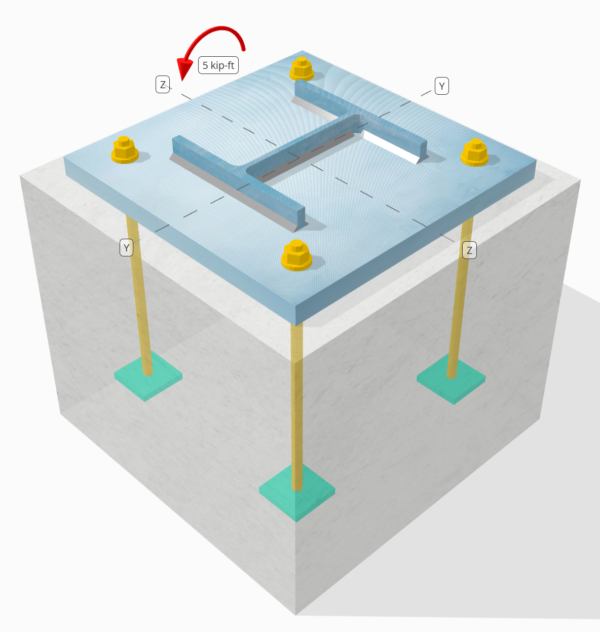
问题陈述
确定设计的列板连接是否足够 5 kip-ft strong-axis moment.
给定数据
柱:
列部分: W8x31
列区域: 9.130 在2
列材料: A992
底盘:
基板尺寸: 15 在x 15 在
基板厚度: 1 在
底板材料: A36
具体:
混凝土尺寸: 18 在x 18 在
混凝土厚度: 15 在
混凝土材料: 3000 压力
焊缝:
焊缝尺寸: 1/4 在
填充金属分类: Ë70XX
仅通过焊缝传输的压缩负荷? 不
SkyCiv 免费工具中的模型
立即使用我们的免费在线工具对上面的底板设计进行建模! 无需注册.
Determine if Low Moment or Large Moment
The calculations for this base plate example, which is subjected to a strong-axis moment, will be based on AISC 设计指南 1, 3RD版. According to the design guide, base plates subjected to moment loads only are classified as the Large Moment Case. This is because no axial load is present to counteract the eccentric load acting on the connection.
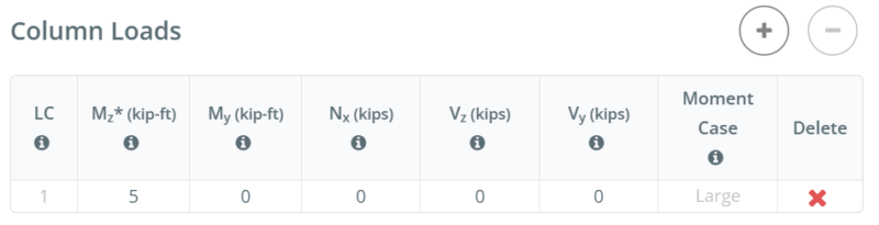
For other load combinations, such as strong-axis bending with axial compression or strong-axis bending with axial tension, determining if the case is Large Moment or Low Moment depends on the actual 列尺寸, base plate size, concrete size, and the given 负载.
In the free version of SkyCiv, the moment case is displayed as you enter the load values. You can access the free tool here to determine the moment case yourself. Straight from the browser, 无需安装.
To learn more about Low Moment and Large Moment case, refer to this SkyCiv article: AISC DG1: 大力矩和小力矩底板
分步计算
检查一下 #1: Weld capacity
We start the design by checking the weld capacity of the connection. We use the Blodgett equations from 焊接结构设计 作者:奥马尔·W. Blodgett to determine the weld section modulus of the weld. We take the weld shape shown below as a simplification.
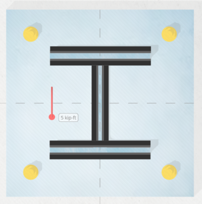
\(S_w = 2d_{col}b_f + \dfrac{(d_{col})^2}{3} = 2 \times 8 \text{ in} \times 8 \text{ in} + \dfrac{(8 \text{ in})^2}{3} = 149.33 \text{ in}^2\)
下一个, we divide the applied bending moment by the weld section modulus to determine the weld stress per unit length. Note that in calculating the weld section modulus, we assume the critical weld stresses occur at the outermost fiber. For a weld in an I-shaped section, the critical locations are at the outer flanges. We get the weld stress as:
\(r_{uw} = \dfrac{M_z}{S_w} = \dfrac{5 \text{ kip·ft}}{149.33 \text{ in}^2} = 0.40179 \text{ kip/in}\)
然后, 我们计算 capacity of the weld. 为一个 0.25 in weld size, the design weld throat is 0.177 在, which is obtained by multiplying the weld size by \(\dfrac{\sqrt{2}}{2}\). 使用 AISC 360-22 情商. J2-4, the weld capacity per unit length is:
\(\phi r_n = \phi 0.6F_{exx}E_w k_{ds} = 0.75 \times 0.6 \times 70 \text{ ksi} \times 0.177 \text{ in} \times 1 = 5.5755 \text{ kip/in}\)
以来 0.40179 KPI < 5.5755 KPI , the column weld capacity is 充足的.
This weld check investigates the weld stress at the tension flange. Since the geometry is symmetric and the only load is a moment acting at the center, we can assume the stress at the compression flange is the same as the stress at the tension flange. 因此, the welds at the compression flange also have enough capacity.
在这个设计实例中, 然而, the design inputs specify that compression is not transferred through the welds, but through 轴承. 从而, in the next check, we evaluate the bearing capacity of the column.
检查一下 #2: Calculate column bearing capacity
After evaluating the weld capacity, we make sure the column has enough capacity to bear on the base plate. This is necessary because we assume the welds do not carry the compression load.
第一, 我们确定 compressive stress at the critical section, which is still the flange. We then add any contribution from axial compression. 在这种情况下, there is none.
\(r_u = \dfrac{N_x}{A_{col}} + \dfrac{M_z 0.5d_{col}}{I_{zz,col}} = \dfrac{0 \text{ kip}}{9.13 \text{ in}^2} + \dfrac{5 \text{ kip·ft} \times 0.5 \times 8 \text{ in}}{110 \text{ in}^4} = 2.1818 \text{ ksi}\)
然后, 我们用 AISC 360-22 Section J7 Eq. J7-1 确定 承载能力:
\(\phi r_n = \phi 1.8F_{y\_col} = 0.75 \times 1.8 \times 50 \text{ ksi} = 67.5 \text{ ksi}\)
以来 2.1818 KSI < 67.5 KSI, 柱轴承能力为 充足的.
通常, this check is not governing.
检查一下 #3: 计算混凝土轴承能力
To calculate the concrete bearing capacity, we need two areas. See the figure below as a guide.
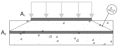
- A1 – Base plate loaded area
- A2 – Area of the concrete support with the same shape as A1
A1 是个 loaded area of the base plate, 尽管 A2 是个 same loaded area projected at a 2H:1V slope into the concrete support. More details on these areas can be found in ACI 318-19 部分 22.8.3.2.
在这个 base plate design with moment, the A1 area will be calculated using the full width of the base plate, \(B\) 和 actual bearing length, \(Y\). The actual bearing length is measured from the edge of the base plate at the compression side towards the center of the plate.
\( A_1 = B \times Y \)
For most engineers, calculating A1 and A2 requires a lot of work, so they simply assume A1 = A2, 这是保守的. 在里面 SkyCiv底板软件, 迭代 are performed to determine the actual A1 values and to maximize the capacity of the base plate.
The table below shows the iteration steps from SkyCiv to determine the bearing length Y, 然后, to determine the actual A1 and A2 areas.

第一, an initial Y is assumed, and the A2 and A1 values are calculated based on the initial Y. These are then used to calculate the maximum bearing strength of the concrete, \(f_{p\_max}\), 以及相应的 bearing force per unit length, \(q_{max}\). Once these are determined, the corresponding Y value is determined based on 情商. 4-32 of AISC DG1 3RD 版. If the calculated Y does not match the initial Y, another iteration step is performed. A more detailed step-by-step calculation of the last iteration is shown in the next section.
现在, taking the A2 and A1 values from the iteration, 我们用 情商. 4-2 of AISC Design Guide 1, 3RD版, to determine \(f_{p\_max}\), the design bearing strength for concrete crushing:
\(f_{p\_max} = \phi \left( \min \left( 0.85 \, (f_c’) \sqrt{\dfrac{A_2}{A_1}}, \, 1.7 \, (f_c’) \right) \right)\)
\(f_{p\_max} = 0.65 \times \left( \min \left( 0.85 \times (3 \text{ ksi}) \times \sqrt{39.941}, \, 1.7 \times (3 \text{ ksi}) \right) \right) = 3.315 \text{ ksi}\)
另外, since this design is a Large Moment Case, the base plate has both a compression side and a tension side. 在这种情况下, we should allow the concrete bearing to be at its full capacity and minimize the Y value. 所以, any remaining tensile force, based on equilibrium of forces, will be taken by the anchors at the tension side.
Given this, we set \(f_{p\_actual}\) 我们将插入已知值 \(f_{p\_max}\).
\(f_{p\_actual} = f_{p\_max} = 3.315 \text{ ksi}\)
以来 3.315 ksi ≤ 3.315 KSI, 混凝土轴承能力是 充足的.
检查一下 #4: Calculate base plate yielding capacity at the bearing interface
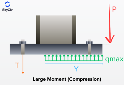
The next step is to determine if the base plate has enough capacity for the given load. As the moment load pushes the base plate against the concrete, the base plate has a tendency to yield due to flexure. We call this check the base plate yielding check on the bearing interface. There is also a separate yielding due to the tension load, and it will be covered in the next design check.
To check the base plate yielding, we need to determine the \(q_{max}\), which is the compression force per unit length. AISC DG1 3rd Ed. 情商. 4-37 给出 \(q_{max}\)作为:
\(q_{max} = f_{p\_max}B_{bp} = 3.315 \text{ ksi} \times 15 \text{ in} = 49.725 \text{ kip/in}\)
然后, we will calculate the Y-dimension. Although the Y-dimension is already calculated in the prior check, this section will show how we use the equations from AISC DG1. For this Large Moment Case, 我们用 情商. 4-32 of AISC DG1, 3RD版.
For the plus case:
\(Y_{case1} = \left( f + \dfrac{L_{bp}}{2} \right) + \sqrt{\left( \left( f + \dfrac{L_{bp}}{2} \right)^2 \right) – \dfrac{2M_z}{q_{max}}}\)
\(Y_{case1} = \left( 5.5315 \text{ in} + \dfrac{15 \text{ in}}{2} \right) + \sqrt{\left( \left( 5.5315 \text{ in} + \dfrac{15 \text{ in}}{2} \right)^2 \right) – \dfrac{2 \times 5 \text{ kip·ft}}{49.725 \text{ kip/in}}}\)
\(Y_{case1} = 25.97 \text{ in}\)
For the minus case:
\(Y_{case2} = \left( f + \dfrac{L_{bp}}{2} \right) – \sqrt{\left( \left( f + \dfrac{L_{bp}}{2} \right)^2 \right) – \dfrac{2M_z}{q_{max}}}\)
\(Y_{case2} = \left( 5.5315 \text{ in} + \dfrac{15 \text{ in}}{2} \right) – \sqrt{\left( \left( 5.5315 \text{ in} + \dfrac{15 \text{ in}}{2} \right)^2 \right) – \dfrac{2 \times 5 \text{ kip·ft}}{49.725 \text{ kip/in}}}\)
\(Y_{case2} = 0.092925 \text{ in}\)
Note that this equation has + 和 – 符号, so we get two values. 从这里, we need to determine which value makes more sense. 以来 25.97 在 is greater than the base plate length, 15 在, we will not consider this value. 所以, 我们将使用 0.092925 在 作为 轴承长度.
\(Y = Y_{case2} = 0.092925 \text{ in}\)
下一个, we calculate the cantilever lengths. 这些是 m and n dimensions from the figure below. 这是基于 AISC DG1 3rd Edition Section 4.3.1.
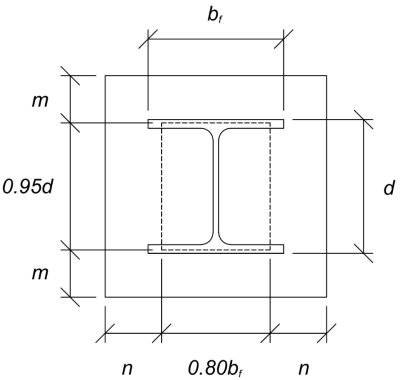
The calculated m and n cantilever values are:
\(m = \dfrac{L_{bp} – 0.95d_{col}}{2} = \dfrac{15 \text{ in} – 0.95 \times 8 \text{ in}}{2} = 3.7 \text{ in}\)
\(n = \dfrac{B_{bp} – 0.8b_f}{2} = \dfrac{15 \text{ in} – 0.8 \times 8 \text{ in}}{2} = 4.3 \text{ in}\)
然后, 我们将 compare the calculated Y value to the larger of m and n. Since Y is less than the larger cantilever length, 我们将使用 AISC DG1 3rd Ed. 情商. 4-52一个. This gives the required base plate thickness to be:
\(t_{p(req)} = \sqrt{\dfrac{4f_{p\_actual}Y \left( n – \dfrac{Y}{2} \right)}{\phi F_{y\_bp}}}\)
\(t_{p(req)} = \sqrt{\dfrac{4 \times 3.315 \text{ ksi} \times 0.092925 \text{ in} \times \left( 4.3 \text{ in} – \dfrac{0.092925 \text{ in}}{2} \right)}{0.9 \times 36 \text{ ksi}}} = 0.4022 \text{ in}\)
最后, let’s compare it to the actual base plate thickness.
\(t_{p(actual)} = t_{bp} = 1 \text{ in}\)
以来 0.4022 在 < 1 在, the yielding capacity of the base plate is 充足的.
检查一下 #5: Calculate base plate yielding capacity at the tension interface
The required tensile force on the anchors at the tension side is equal to the resulting compression force on the compression side. This is because the base plate is only loaded with moment loads, and so the resulting couple forces are equal in magnitude.
To calculate the required strength of anchors, 我们用 AISC DG1 3rd Ed. 情商. 4-31.
\(T_u = q_{max}Y = 49.725 \text{ kip/in} \times 0.092925 \text{ in} = 4.6207 \text{ kip}\)
然后, 我们计算 eccentricity of this tensile force from the column support. This is taken from the center of the anchor rod to the center of the column flange. 我们使用 情商. 4-61 of the design guide to determine the eccentricity. In the equation, f is the distance of the anchor rod from the column centerline.
\(x = \left( f – \dfrac{d_{col}}{2} \right) + \dfrac{t_f}{2} = \left( 5.5315 \text{ in} – \dfrac{8 \text{ in}}{2} \right) + \dfrac{0.435 \text{ in}}{2} = 1.749 \text{ in}\)
Note that in this analysis, we take the whole base plate width as the section to resist the flexure, as we closely follow the AISC DG1 3rd Ed. guidelines. Other conservative bending widths could also be used.
最后, we determine the required base plate thickness 使用 情商. 4-62一个.
\(t_{p(req)} = \sqrt{\dfrac{4T_u x}{B_{bp}\phi F_{y\_bp}}} = \sqrt{\dfrac{4 \times 4.6207 \text{ kip} \times 1.749 \text{ in}}{15 \text{ in} \times 0.9 \times 36 \text{ ksi}}} = 0.25791 \text{ in}\)
以来 0.25791 在 < 1 在, 的 yielding capacity of the base plate is 充足的.
检查一下 #6: 锚固支票
The rest of the anchor design checks are not shown in this example. Please refer to other SkyCiv Base Plate Design Examples that covers capacity of 锚地.
设计概要
SkyCiv基板设计软件可以自动生成此设计示例的分步计算报告. 它还提供了执行的检查及其结果比率的摘要, 一目了然地使信息易于理解. 以下是示例摘要表, 报告中包括.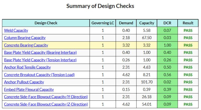
购买基板软件
单独购买基本板设计模块的完整版本,而没有任何其他SkyCiv模块. 这为您提供了底板设计的完整结果, 包括详细报告和更多功能.

