
Moment Bağlantısı Nedir?
Bir anlık bağlantı, aktaran bir bağlantıdır bükülme anı bir sütun ve bir kiriş arasında, veya herhangi iki üye arasında. Bir kiriş ucunda iç moment taşıyorsa, bağlantı, ucun serbestçe dönmesine izin vermek yerine, o anı bağlantı noktası boyunca taşımalıdır.
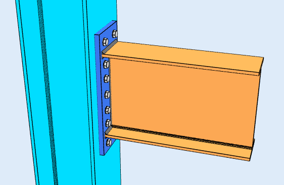
Genişletilmiş uç plaka bağlantısı, anlık bağlantıya bir örnek. Germe flanşının dışındaki cıvatalar çifte daha uzun bir kaldıraç kolu sağlar.
Amacı bir an bağlantısı son rotasyonu tutmaktır, analiz açısından hangisi sabitlik kodu FFFFFF: her üç ötelemede ve üç döndürmede de sınırlandırılmıştır. Bu nedenle moment bağlantılarına katı bağlantılar da denilmektedir..
AISC 360-16 Bölüm B3.4 bu konuda daha kesindir, ve çerçeveyi modellediğinizde ayrım önemlidir. Bir anlık bağlantı ya tamamen ölçülü (moment bağlantıları ile aynı tasarım zorluğunu oluşturmazlar), üyeler arasındaki açıyı tutan ve FFFFFF varsayımını doğrulayan, veya kısmen kısıtlanmış (halkla ilişkiler), Momenti aktaran ancak analizin bağlantının gerçek sertliğini hesaba katmasını sağlayacak kadar dönen. Bir PR eklemini tamamen rijit olarak ele almak, çerçevenin sertliğini abartıp kaymasını olduğundan az gösterir.
nerede kesme bağlantısı çoğunlukla ışın ağı üzerinden çalışır, bir anlık bağlantı flanşlara bağlanmalıdır, çünkü bükülme geriliminin olduğu yer burasıdır. Flanş plakaları, kaynaklı flanşlar veya uç plakaların tümü aynı işi yapar: kirişin momentini bir flanşta çekme kuvvetine, diğerinde ise sıkıştırma kuvvetine dönüştürürler, ve bu çifti sütuna taşıyın.
Moment Bağlantı Tipleri
Moment bağlantıları kesme bağlantısından çok daha fazla moment taşır, ve bunları yapmak daha pahalıya mal oluyor: daha fazla malzeme, daha fazla kaynak, daha fazla uyum ve daha fazla denetim. Çoğu çerçeve bunları yalnızca yapının yanal stabilite için çerçeve hareketine dayandığı durumlarda kullanır, ve diğer her yerde kesme bağlantılarını kullanın.
Hangi konfigürasyonların mevcut olduğu tasarım koduna ve kirişin neye çerçevelendiğine bağlıdır.
I kesitli sütuna kiriş (AISC 360-16)
Dört konfigürasyon, kolon flanşına veya kolon ağına çerçeveleme.
Flanş Plakası
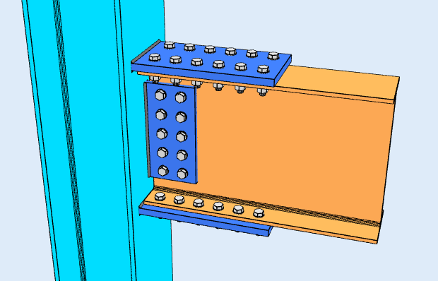
Plakalar kirişin üst ve alt flanşları boyunca uzanır, kirişe ve kolona cıvatalanmış veya kaynaklanmış. Kiriş büküldükçe, plakalardan biri gerilime, diğeri ise baskıya girer, ve o çift anı taşıyor. Kiriş ağı genellikle ayrı bir kesme plakası tarafından taşınır, yani bağlantı işi böler: flanşlar anı alır, ağ makası alıyor.
Kaynaklı Flanşlar
Kiriş flanşları doğrudan kolon flanşına kaynaklanmıştır, ara plakası olmayan, ve ağ bir kesme tırnağına cıvatalanmıştır. Bu, grubun en sağlam bağlantısını ve en temiz yük yolunu sağlar, ancak tolerans dahilinde uyması gereken bir eleman üzerinde saha kaynağıdır, yani ön ısıtmayı taşır, Cıvatalı bir detayın karşılamadığı erişim ve inceleme maliyetleri.
Gömme Uç Plakası
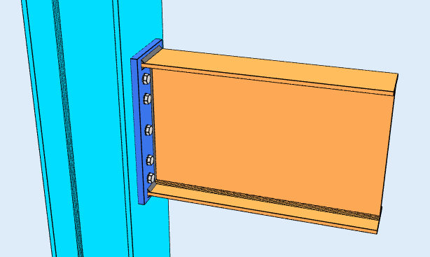
Kirişin ucuna kaynak yapılmış ve kolona cıvatalanmış bir plaka, plaka, kiriş flanşlarıyla aynı hizada olacak ve tüm cıvatalar bunların arasına oturacak şekilde. Daha düşük anlara uygundur, çünkü cıvata grubunun kaldıraç kolu kiriş derinliği ile sınırlıdır.
Genişletilmiş Uç Plaka
Aynı fikir, cıvataların dışarıda durabilmesi için plaka gergi flanşını geçecek şekilde uzatılmış halde. Bu dış cıvataların sıkıştırma flanşı etrafında daha uzun bir kaldıraç kolu vardır, ekstra an kapasitesini satın alan şey budur. Uzatılmış kısımdaki meraklı eylem, bir yönetim kontrolü haline gelir. Bu sayfanın üst kısmında gösterilen konfigürasyondur.
Her iki uç plaka konfigürasyonu da moment bağlantı hesaplayıcısı.
HSS sütununa kiriş (AISC 360-16)
Bir moment bağlantısını içi boş bir bölüme çerçevelemek daha zordur, çünkü cıvatalanacak bir flanş yok ve uzak tarafa erişim yok. Bir konfigürasyon mevcut: a flanş plakası HSS'nin yüzüne kaynaklanmıştır, takviyeler olmadan.
GİBİ 4100:2020
GİBİ 4100 SkyCiv Bağlantı Tasarımı kapsamı yalnızca kesme bağlantılarını kapsar, kirişi I kesitli kolona veya kirişten kirişe çerçeveleme. AS'ye anlık bağlantılar 4100 mevcut değil. Anlık tasarım için, AISC'yi kullan 360-16.
Yazılım neyi kontrol ediyor??
Detaylandırma ilk önce çalışır: cıvata kenar mesafeleri, cıvata aralığı (adım ve ölçü), takım açıklıkları, minimum ve maksimum plaka boyutları, ve plakalar arasında çatışma tespiti, sertleştiriciler, cıvatalar ve kaynaklar. Kurulamayan bağlantı çözüme ulaşmaz.
Güç kontrolleri daha sonra çifti eklem boyunca takip eder. Flanş tarafında bu, plakanın hem gerilimde hem de basınçta olduğu anlamına gelir, cıvata kesme, cıvata yatağı ve yırtılma, blok kesme kopması, cıvatalar üzerinde meraklı eylem, ve kaynak boğaz gerilimi. Destek elemanında yerel flanş bükülmesi anlamına gelir, web yerel verimi ve web'in sakatlanması, kolonun takviyelere mi yoksa katlayıcı plakaya mı ihtiyacı olduğuna karar veren sınır durumlar nelerdir.
Her formül, tasarım kontrolü ve kod referansı tam olarak gösterilir, AISC'den madde numaraları ile 360-16, böylece hesaplamaya güvenmek yerine takip edebilirsiniz.
Moment Bağlantısı ve Kesme Bağlantısı: fark
Fark, iki üye arasındaki açıya ne olduğudur. Bir anlık bağlantıda bu açı tutulur, böylece bir üyedeki bükülme diğerine taşınır. Kesme bağlantısında eklem serbestçe dönebilir, böylece kiriş ucu döner ve eklemden anlamlı bir an geçmez.
| Moment Bağlantısı | Kesme Bağlantısı | |
|---|---|---|
| Aktarılan Kuvvetler | Kesme ve Moment | Yalnızca kesme |
| Alternatif isimler | Sert, Sabit, Anı dirençli | Sabitlendi, Menteşe, Basit |
| AISC 360-16 terim | FR veya PR moment bağlantısı | Basit bağlantı |
| Rotasyon | Rotasyonu kısıtlar | Döndürmek ücretsiz |
| Yazılım Sabitleme Kodu | FFFFFF | FFFFFR |
SkyCiv Bağlantı Tasarım Yazılımı
Yukarıdaki modeller ve kontroller SkyCiv Bağlantı Tasarımı. Üzerini kapsıyor 80+ önceden yapılandırılmış bağlantı türleri, için tasarımlar AISC 360-16 LRFD ve ASD'de ve GİBİ 4100:2020, ve her formülü gösterir, tam tasarım kontrolü ve kod referansı.
Bağlantıyı 3 boyutlu olarak modelleyebilirsiniz, cıvataları değiştir, yük verilerinizi kaybetmeden kaynaklar veya plakalar, CloudCAD'de 2D detay çizim sayfaları oluşturun, ve Revit'te koordinasyon için 3D geometriyi IFC'ye aktarın, Tekla veya Navisworks.
Tamamen tarayıcıda çalışır, indirmesiz, güncellemeler veya BT kurulumu.
