
To design a bolted flange plate moment connection to AISC 360, you turn the beam end moment into a pair of flange forces and check everything that force passes through. That means slip of the flange bolts, cıvata yatağı ve yırtılma, blok kesme, tension and compression in the flange plate, tension and flexural rupture of the beam at the holes, the weld to the column, and the column flange and web. A separate web plate carries the shear and is checked like a shear tab.
This page works through one real example from start to finish: a W24x84 beam framing into the flange of a W14x211 column, bir ile 300 kip-ft anı, a 250 kip kesme ve 100 kip of axial load, AISC'ye göre tasarlandı 360-16 LRFD ve AISC Kılavuzu 15. Baskı. The flange plates are 1/2 in thick with eight 1 in A490 slip-critical bolts each, and the web plate is 1 in thick with ten 1 in A490-N bolts. Her denklem sayılarıyla yazılmıştır, AISC hesaplama tablosuyla aynı sırada SkyCiv Bağlantı Tasarımı modül bunun için üretir.
What is a flange plate moment connection?
A flange plate moment connection transfers a beam’s end moment to a column through two plates, one at each beam flange. Each plate is shop-welded to the column flange and field-bolted to the beam flange, and a separate web plate carries the shear. It is a fully restrained (moment bağlantıları ile aynı tasarım zorluğunu oluşturmazlar) an bağlantısı under AISC 360-16 B3.4(b).
It is also called a bolted flange plate or flange-plated moment connection. Fabricators like it because all the welding happens in the shop and the beam is only bolted in the field. The flange plates carry the moment as a tension and compression couple, the web plate is a single plate connection (a shear tab) for the shear, and the column has to take the concentrated flange forces. You can check this one directly in the flanş plakası bağlantı hesaplayıcısı, and the other types are on the moment bağlantıları sayfa.
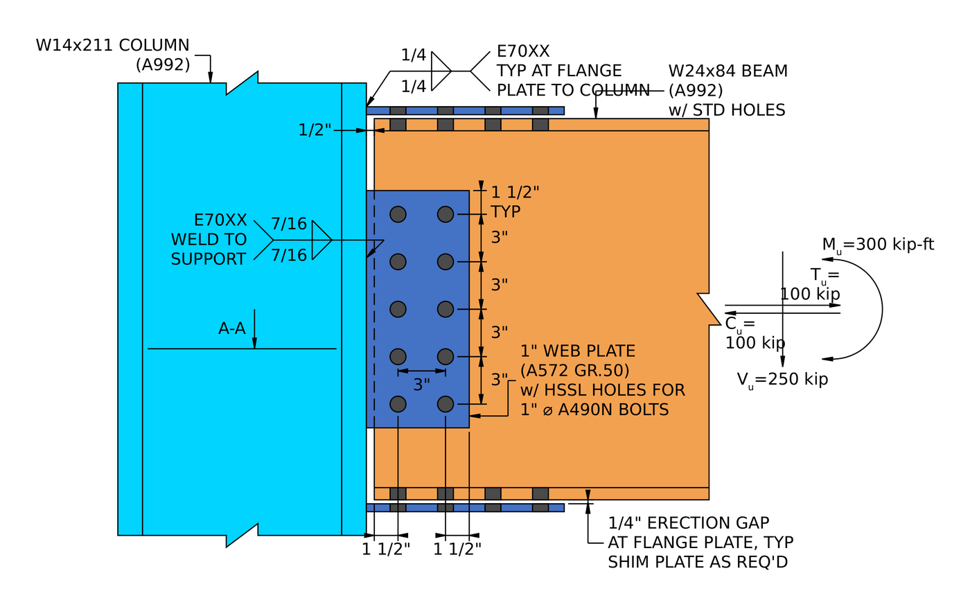
Örnek bağlantının yüksekliği. The flange plates are welded to the column with 1/4 in fillets and bolted to the beam flanges. The web plate is welded with 7/16 in fillets and bolted to the beam web. Var 1/4 in erection gap at each flange plate, filled with shims as required.
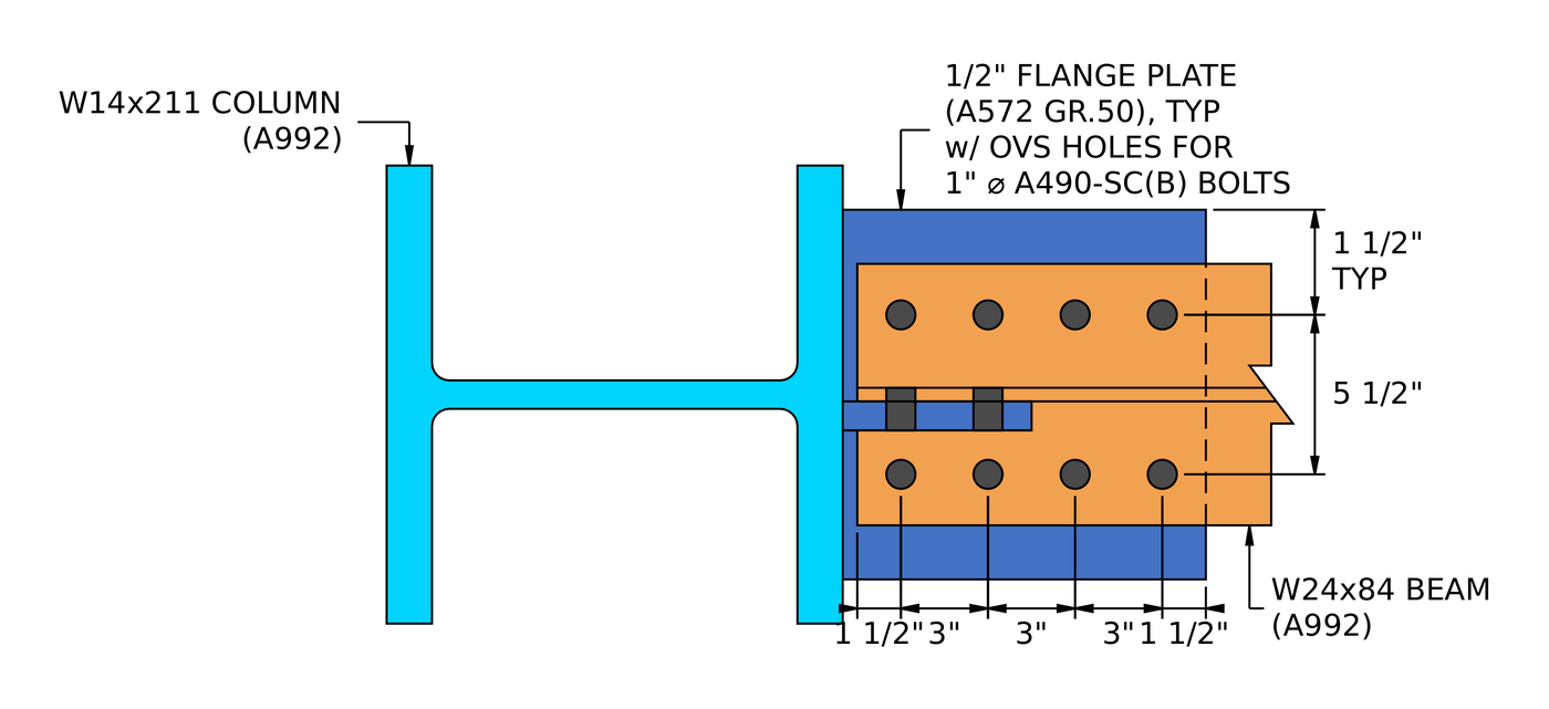
Bölüm A-A. Each flange plate has two lines of four bolts at a 5 1/2 ölçü olarak, in oversized holes in the plate and standard holes in the beam flange.
How do you design a flange plate moment connection? Bir bakışta adımlar
The flange plate connection is checked first, for the flange force from the moment and axial load. The web plate is checked second, for the shear.
- Check the detailing limits at the beam flange: ölçü, aralık ve kenar mesafeleri.
- Find the flange force and check slip of the slip-critical bolts.
- Flanş plakasındaki cıvata yatağını ve yırtılmayı kontrol edin.
- Kiriş flanşındaki cıvata yatağını ve yırtılmayı kontrol edin.
- Üç yırtma modeli için flanş plakasının blok kesmesini kontrol edin.
- Kiriş flanşının blok kesmesini kontrol edin.
- Flanş plakasındaki gerginlik ve kopmayı kontrol edin.
- Kirişin gerilim kopmasını kontrol edin, kesme gecikmeli.
- Flanş cıvata deliklerinde kirişin eğilme kopmasını kontrol edin.
- Flanş plakasını basınç altında kontrol edin.
- Check the detailing limit at the column face.
- Check the fillet weld from the flange plate to the column flange.
- Check the column flange and web for the concentrated flange force.
- Check the detailing limits for the web plate.
- Check bolt group shear on the web plate.
- Check bolt bearing and tear-out on the web plate.
- Kiriş ağındaki cıvata yatağını ve yırtılmayı kontrol edin.
- Kesmeyi birleştir, Etkin grup gücü için cıvata başına yatak ve yırtılma.
- Check block shear of the web plate.
- Check shear yielding and shear rupture of the web plate.
- Check the detailing limit for the web plate weld.
- Check the fillet weld from the web plate to the column flange.
Bu örnek için tasarım girdileri
Tasarım kodu AISC'dir 360-16 LRFD. Bölüm özellikleri AISC Kılavuzundan alınmıştır.
| Kalem | Sembol | Değer |
|---|---|---|
| Faktoringli dikey kesme | [mathin] V_{u} [mathin] | 250 kip |
| Faktörlü eksenel gerilim | [mathin] T_{u} [mathin] | 100 kip |
| Faktörlü eksenel sıkıştırma | [mathin] C_{u} [mathin] | 100 kip |
| Faktörlü güçlü eksen momenti | [mathin] M_{ux} [mathin] | 300 acı |
| Kalem | Sembol | Değer |
|---|---|---|
| Işın | W24x84, A992 | |
| Işın derinliği | [mathin] d_{bm} [mathin] | 24.1 içinde |
| Kiriş ağ kalınlığı | [mathin] t_{wb} [mathin] | 0.47 içinde |
| Kiriş flanş genişliği / kalınlık | [mathin] b_{fb},\ t_{fb} [mathin] | 9.02 içinde / 0.77 içinde |
| Işın alanı | [mathin] A_{bm} [mathin] | 24.7 inç² |
| Beam elastic section modulus | [mathin] S_{x} [mathin] | 196.46 inç³ |
| Işın verimi / çekme gerilimi | [mathin] F_{yb},\ F_{ub} [mathin] | 50 ksi / 65 ksi |
| Sütun | W14x211, A992 | |
| Sütun derinliği | [mathin] d_{sup} [mathin] | 15.7 içinde |
| Column web thickness | [mathin] t_{ws} [mathin] | 0.98 içinde |
| Sütun flanş genişliği / kalınlık | [mathin] b_{fs},\ t_{fs} [mathin] | 15.8 içinde / 1.56 içinde |
| Sütun alanı | [mathin] A_{sup} [mathin] | 62 inç² |
| Column kdes / T dimension | [mathin] k_{des},\ T [mathin] | 2.16 içinde / 10 içinde |
| Sütun verimi / çekme gerilimi | [mathin] F_{ys},\ F_{us} [mathin] | 50 ksi / 65 ksi |
| Esneklik modülü | [mathin] E [mathin] | 29000 ksi |
| Flange plate connection | Sembol | Değer |
|---|---|---|
| Flanş plakası | PL 1/2 x 12 3/4 x 12 1/2, A572 Gr. 50 | |
| Plaka genişliği / uzunluk / kalınlık | [mathin] b_{fp},\ L_{fp},\ t_{fp} [mathin] | 12.75 içinde / 12.5 içinde / 0.5 içinde |
| Plaka verimi / çekme gerilimi | [mathin] F_{yp},\ F_{up} [mathin] | 50 ksi / 65 ksi |
| Cıvatalar | 1 A490-SC'de, B sınıfı, tek kayma düzlemi | |
| Cıvata nominal gerilmesi / kayma gerilmesi | [mathin] F_{nt},\ F_{nv} [mathin] | 113 ksi / 68 ksi |
| Plakadaki delikler / kiriş flanşı | Büyük boy (OV'ler) / liste yalnızca ABD'nin materyallerini içerir (STD) | |
| Cıvata satırları / ölçü | [mathin] n_{r},\ g_{a} [mathin] | 2 / 5.5 içinde |
| Cıvata sütunları / sütun aralığı | [mathin] n_{c},\ s_{c} [mathin] | 4 / 3 içinde |
| Dikey / horizontal edge distance on beam flange | [mathin] L_{ev,bf},\ L_{eh,bf} [mathin] | 1.76 içinde / 1.5 içinde |
| Dikey / horizontal edge distance on flange plate | [mathin] L_{ev,fp},\ L_{eh,fp} [mathin] | 3.625 içinde / 1.5 içinde |
| Unbraced length of flange plate | [mathin] L_{k,fp} [mathin] | 3 içinde |
| Kaynak, flange plate to column | [mathin] W,\ F_{EXX} [mathin] | 1/4 içinde (0.25 içinde) fileto, E70XX, 70 ksi |
| Web plate connection | Sembol | Değer |
|---|---|---|
| Web plakası (tek plaka) | PL 1 x 6 1/2 x 15, A572 Gr. 50 | |
| Plaka genişliği / derinlik / kalınlık | [mathin] b_{p},\ d_{p},\ t_{p} [mathin] | 6.5 içinde / 15 içinde / 1 içinde |
| Plaka verimi / çekme gerilimi | [mathin] F_{yp},\ F_{up} [mathin] | 50 ksi / 65 ksi |
| Cıvatalar | 1 in A490-N, tek kesme | |
| Cıvata nominal gerilmesi / kayma gerilmesi | [mathin] F_{nt},\ F_{nv} [mathin] | 113 ksi / 68 ksi |
| Plakadaki delikler / ışın ağı | Kısa oluklu yatay (HSSL) / liste yalnızca ABD'nin materyallerini içerir (STD) | |
| Cıvata satırları / satır aralığı | [mathin] n_{r},\ s_{r} [mathin] | 5 / 3 içinde |
| Cıvata sütunları / sütun aralığı | [mathin] n_{c},\ s_{c} [mathin] | 2 / 3 içinde |
| Kolondan kiriş web açıklığı | [mathin] clr [mathin] | 0.5 içinde |
| Kiriş ağındaki yatay kenar mesafesi / tabak | [mathin] L_{eh,bm},\ L_{eh,pl} [mathin] | 1.5 içinde / 1.5 içinde |
| Plaka üzerinde dikey kenar mesafesi | [mathin] L_{ev,pl} [mathin] | 1.5 içinde |
| Cıvata grubu eksantrikliği | [mathin] e [mathin] | 3.5 içinde |
| Kaynak, web plate to column | [mathin] W,\ F_{EXX} [mathin] | 7/16 içinde (0.4375 içinde) fillet both sides, E70XX, 70 ksi |
Bölüm 1: the flange plate connection
Adımlar 1 -e 13 check the flange plates, the beam flanges, the welds to the column and the column itself, all for the flange force worked out in Step 2.
Adım 1: Detailing limits at the beam flange (AISC 360-16 J3.3, J3.4, J3.5)
Herhangi bir güç kontrolünden önce, Cıvata düzeni oluşturulabilir olmalı ve mukavemet denklemlerinin ardındaki varsayımlarla eşleşmelidir.. Çok yakın cıvatalar delikler arasında yırtılır, ve çok yakın olan kenarlar yırtılır.
Minimum cıvata aralığı [mathin] 2\tfrac{2}{3} d_{b} [mathin] J3.3'ten. Minimum kenar mesafesi 1 cıvatada 1 1/4 Tablo J3.4'ten, kiriş flanşındaki sınır budur, deliklerin standart olduğu yer. Flanş plakasında büyük boyutlu delikler bulunur, yani Tablo J3.5 şunu ekliyor: 1/8 içinde, which brings its edge distance limits to 1.375 içinde. Göstergenin kendi minimum değeri vardır, böylece iki cıvata hattı flanşın üzerine oturacak ve cıvataların takılması için yer bırakılacaktır.
[math] s_{min} = 2\tfrac{2}{3}\, d_{b} = 2.667 \times (1\,in) = 2.667\,in [math]
| Detaylandırma sınırı | Sınır (içinde) | Gerçek (içinde) | DCR | Sonuç |
|---|---|---|---|---|
| Minimum cıvata ölçüsü | 4.875 | 5.500 | 0.886 | GEÇMEK |
| Minimum cıvata sütun aralığı | 2.667 | 3.000 | 0.889 | GEÇMEK |
| Maksimum cıvata sütun aralığı | 6.000 | 3.000 | 0.500 | GEÇMEK |
| Plaka minimum dikey kenar mesafesi | 1.375 | 3.625 | 0.379 | GEÇMEK |
| Plaka minimum yatay kenar mesafesi | 1.375 | 1.500 | 0.917 | GEÇMEK |
| Işın minimum dikey kenar mesafesi | 1.250 | 1.760 | 0.710 | GEÇMEK |
| Kirişin minimum yatay kenar mesafesi | 1.250 | 1.500 | 0.833 | GEÇMEK |
Minimum limit için oran, limitin gerçek değere oranıdır, ve maksimum olarak gerçek limit aşımıdır. The governing row is the plate horizontal edge distance:
[math] DCR = \frac{1.375\,in}{1.5\,in} = 0.917 [math]
DCR = 0.917 < 1.0, TAMAM MI
Adım 2: Flange force and slip critical bolt strength (AISC 360-16 J3.8)
The moment is carried as a couple of equal and opposite forces in the two beam flanges, and the flange plate bolts have to carry that force without slipping. Flanş plakasında büyük boyutlu delikler olduğundan bu cıvatalar kayma açısından kritik öneme sahiptir, hangi AISC 360-16 J3.2 yalnızca kayma açısından kritik bağlantılara izin verir.
Flanş kuvveti
The moment is divided by the distance between the beam flange centroids, [mathin] d_{bm} – t_{fb} [mathin]. The web plate is designed for shear only, so the axial load goes to the flange plates, half to each:
[math] P_{uF} = \frac{M_{ux}}{d_{bm} – t_{fb}} + \frac{P_{u}}{2} [math]
[math] P_{uF} = \frac{(300\,kip\text{-}ft)}{(24.1\,in) – (0.77\,in)} + \frac{(100\,kip)}{2} [math]
[math] P_{uF} = 204.31\,kip [math]
The axial tension and compression are both 100 kip, so the flange force is 204.31 her iki şekilde de öp: tension adds to the tension flange and compression adds to the compression flange. Every check in Part 1 uses this one value.
Kayma direnci
Nerede [mathin] \phi = 0.85 [mathin] büyük boyutlu delikler için direnç faktörüdür, [mathin] \mu = 0.5 [mathin] B Sınıfı aşınma yüzeyleri için ortalama kayma katsayısıdır, [mathin] D_{u} = 1.13 [mathin] ortalama kurulu ön gerilimi belirtilen minimum değerle ilişkilendirir, [mathin] h_{f} = 0.85 [mathin] dolgu faktörüdür, [mathin] T_{b} = 64\,kip [mathin] bir şeyin asgari iddiasıdır 1 Tablo J3.1'den A490 cıvatada, ve var [mathin] N_{s} = 1 [mathin] kayma düzlemi:
[math] \phi R_{n} = \phi\, \mu\, D_{u}\, h_{f}\, T_{b}\, N_{s}\, n_{r}\, n_{c} [math]
[math] \phi R_{n} = (0.85) \times (0.5) \times (1.13) \times (0.85) \times (64\,kip) \times (1) \times (2) \times (4) [math]
[math] \phi R_{n} = 209\,kip [math]
DCR = 204.31 kip / 209 kip = 0.978 < 1.0, TAMAM MI
The filler factor of 0.85 is the J3.8 value for two or more fillers between the connected parts. The drawing calls for shims as required at the 1/4 in erection gap, so the design does not count on there being only one. Şurada: 0.978 this is one of the two tightest checks in the connection.
Adım 3: Flanş plakasında cıvata yatağı ve yırtılma (AISC 360-16 J3.10)
Slip-critical bolts must also have enough strength as bearing bolts, eklemin kayması durumunda. Her cıvata plakadaki deliğin kenarını iter. Plaka ya delikte deforme olur (rulman, sınırlı 2.4 d t Fu) veya bir şeridi bir sonraki deliğe veya plakanın ucuna kadar yırtın (yırtma, 1.2 lc t Fu). The bolts nearest the end of the plate have the shortest clear distance, so they are the weak ones.
Clear distance for the end bolts, ile [mathin] d_{h} = 1.25\,in [mathin], the oversized hole dimension along the member length:
[math] l_{c1} = L_{eh,fp} – \frac{d_{h}}{2} = (1.5\,in) – \frac{(1.25\,in)}{2} = 0.875\,in [math]
Clear distance between the other bolts:
[math] l_{c2} = s_{c} – d_{h} = (3\,in) – (1.25\,in) = 1.75\,in [math]
İki hattın her birindeki uç cıvata, [mathin] l_{c1} [mathin], and the other three in each line use [mathin] l_{c2} [mathin]:
[math] \phi R_{n} = \phi \left[ \min\left(1.2\, l_{c1},\, 2.4\, d_{b}\right) t_{fp} F_{up}\, n_{r} + \min\left(1.2\, l_{c2},\, 2.4\, d_{b}\right) t_{fp} F_{up}\, n_{r} \left( n_{c} – 1 \right) \right] [math]
[math] \phi R_{n} = (0.75) \times \left[ \min\left(1.2 \times 0.875\,in,\, 2.4 \times 1\,in\right)(0.5\,in)(65\,ksi)(2) + \min\left(1.2 \times 1.75\,in,\, 2.4 \times 1\,in\right)(0.5\,in)(65\,ksi)(2)(4 – 1) \right] [math]
[math] \phi R_{n} = 358.31\,kip [math]
DCR = 204.31 kip / 358.31 kip = 0.570 < 1.0, TAMAM MI
Adım 4: Kiriş flanşında cıvata yatağı ve yırtılma (AISC 360-16 J3.10)
Aynı kontrol kiriş flanşı için de geçerlidir, standart delikleri olan ([mathin] d_{h} = 1.125\,in [mathin]) and is thicker than the plate.
[math] l_{c1} = L_{eh,bf} – \frac{d_{h}}{2} = (1.5\,in) – \frac{(1.125\,in)}{2} = 0.9375\,in [math]
[math] l_{c2} = s_{c} – d_{h} = (3\,in) – (1.125\,in) = 1.875\,in [math]
[math] \phi R_{n} = \phi \left[ \min\left(1.2\, l_{c1},\, 2.4\, d_{b}\right) t_{fb} F_{ub}\, n_{r} + \min\left(1.2\, l_{c2},\, 2.4\, d_{b}\right) t_{fb} F_{ub}\, n_{r} \left( n_{c} – 1 \right) \right] [math]
[math] \phi R_{n} = (0.75) \times \left[ \min\left(1.2 \times 0.9375\,in,\, 2.4 \times 1\,in\right)(0.77\,in)(65\,ksi)(2) + \min\left(1.2 \times 1.875\,in,\, 2.4 \times 1\,in\right)(0.77\,in)(65\,ksi)(2)(4 – 1) \right] [math]
[math] \phi R_{n} = 591.22\,kip [math]
DCR = 204.31 kip / 591.22 kip = 0.346 < 1.0, TAMAM MI
Adım 5: Flanş plakasının blok kesmesi (AISC 360-16 J4.3)
Flanş plakasının bir bloğu cıvata hatları boyunca yırtılabilir: bir delik hattı boyunca kesme artı plaka boyunca gerilim. İki cıvata çizgisiyle bunun gerçekleşmesinin üç yolu vardır, ve en zayıf olan yönetir. Her delik eklenir 1/16 Delme sırasında hasar için (B4.3), ve [mathin] d_{h} = 1.25\,in [mathin] for the oversized holes in both directions.
L deseni: bir kesme düzlemi, cıvataların bir kenarına kadar gerginlik
[math] A_{nt} = t_{fp} \left[ (n_{r} – 2)\, s_{r} + g_{a} + L_{ev,fp} – (n_{r} – 0.5)\left( d_{h} + 0.0625\,in \right) \right] [math]
[math] A_{nt} = (0.5\,in) \times \left[ (2 – 2)(3\,in) + 5.5\,in + 3.625\,in – (2 – 0.5)(1.25\,in + 0.0625\,in) \right] = 3.5781\,in^{2} [math]
[math] A_{gv} = t_{fp} \left[ L_{eh,fp} + (n_{c} – 1)\, s_{c} \right] = (0.5\,in) \times \left[ 1.5\,in + (4 – 1)(3\,in) \right] = 5.25\,in^{2} [math]
[math] A_{nv} = t_{fp} \left[ L_{eh,fp} + (n_{c} – 1)\, s_{c} – (n_{c} – 0.5)\left( d_{h} + 0.0625\,in \right) \right] = (0.5\,in) \times \left[ 1.5\,in + (3)(3\,in) – (3.5)(1.3125\,in) \right] = 2.9531\,in^{2} [math]
İle [mathin] U_{bs} = 1 [mathin] düzgün gerginlik için:
[math] \phi R_{n} = \phi \left( 0.6\, F_{up} A_{nv} + U_{bs} F_{up} A_{nt} \right) \le \phi \left( 0.6\, F_{yp} A_{gv} + U_{bs} F_{up} A_{nt} \right) [math]
[math] \phi R_{n} = (0.75) \left( 0.6 \times 65 \times 2.9531 + 1 \times 65 \times 3.5781 \right) \le (0.75) \left( 0.6 \times 50 \times 5.25 + 1 \times 65 \times 3.5781 \right) [math]
[math] \phi R_{n} = 260.81\,kip [math]
U deseni: iki kesme düzlemi, cıvata çizgileri arasındaki gerginlik
[math] A_{gv} = 2\, t_{fp} \left[ L_{eh,fp} + (n_{c} – 1)\, s_{c} \right] = 2 \times (0.5\,in) \times \left[ 1.5\,in + (3)(3\,in) \right] = 10.5\,in^{2} [math]
[math] A_{nv} = 2\, t_{fp} \left[ L_{eh,fp} + (n_{c} – 1)\, s_{c} – (n_{c} – 0.5)\left( d_{h} + 0.0625\,in \right) \right] = 5.9062\,in^{2} [math]
[math] A_{nt} = t_{fp} \left[ (n_{r} – 2)\, s_{r} + g_{a} – (n_{r} – 1)\left( d_{h} + 0.0625\,in \right) \right] = (0.5\,in) \times \left[ 0 + 5.5\,in – (1)(1.3125\,in) \right] = 2.0937\,in^{2} [math]
[math] \phi R_{n} = (0.75) \left( 0.6 \times 65 \times 5.9062 + 1 \times 65 \times 2.0937 \right) \le (0.75) \left( 0.6 \times 50 \times 10.5 + 1 \times 65 \times 2.0937 \right) = 274.83\,kip [math]
2L deseni: iki kesme düzlemi, her cıvata hattından kenarına kadar gerginlik
[math] A_{nt} = 2\, t_{fp} \left[ L_{ev,fp} – 0.5\left( d_{h} + 0.0625\,in \right) \right] = 2 \times (0.5\,in) \times \left[ 3.625\,in – 0.5 \times (1.3125\,in) \right] = 2.9687\,in^{2} [math]
[math] \phi R_{n} = (0.75) \left( 0.6 \times 65 \times 5.9062 + 1 \times 65 \times 2.9687 \right) \le (0.75) \left( 0.6 \times 50 \times 10.5 + 1 \times 65 \times 2.9687 \right) = 317.48\,kip [math]
Yönetim blok kesmesi
[math] \phi R_{n} = \min\left( 260.81\,kip,\, 274.83\,kip,\, 317.48\,kip \right) = 260.81\,kip [math]
DCR = 204.31 kip / 260.81 kip = 0.783 < 1.0, TAMAM MI
L modeli geçerlidir çünkü tek bir kayma düzlemi vardır. NS 12.75 in plate is wider than the 9.02 in beam flange, which gives the outer strips plenty of tension area in the 2L pattern.
Adım 6: Kiriş flanşının blok kesmesi (AISC 360-16 J4.3)
Kiriş flanşı da aynı şekilde yırtılabilir. Its edges are only 1.76 in outside the bolt lines, so the critical block is the 2L pattern: the two outer strips of flange shear along the bolt lines and pull away in tension.
[math] A_{nt} = t_{fb} \left[ b_{fb} – g_{a} – (n_{r} – 1)\left( d_{h} + 0.0625\,in \right) \right] = (0.77\,in) \times \left[ 9.02\,in – 5.5\,in – (1)(1.125\,in + 0.0625\,in) \right] = 1.796\,in^{2} [math]
[math] A_{gv} = 2\, t_{fb} \left[ L_{eh,bf} + (n_{c} – 1)\, s_{c} \right] = 2 \times (0.77\,in) \times \left[ 1.5\,in + (3)(3\,in) \right] = 16.17\,in^{2} [math]
[math] A_{nv} = 2\, t_{fb} \left[ L_{eh,bf} + (n_{c} – 1)\, s_{c} – (n_{c} – 0.5)\left( d_{h} + 0.0625\,in \right) \right] = 2 \times (0.77\,in) \times \left[ 10.5\,in – (3.5)(1.1875\,in) \right] = 9.7694\,in^{2} [math]
[math] \phi R_{n} = (0.75) \left( 0.6 \times 65 \times 9.7694 + 1 \times 65 \times 1.796 \right) \le (0.75) \left( 0.6 \times 50 \times 16.17 + 1 \times 65 \times 1.796 \right) [math]
[math] \phi R_{n} = 373.31\,kip [math]
DCR = 204.31 kip / 373.31 kip = 0.547 < 1.0, TAMAM MI
Adım 7: Flanş plakasının gerilmesi ve kopması (AISC 360-16 J4.1)
On the tension side, flanş plakası kısa bir gerilim elemanıdır. Brüt kesiti akmamalı, ve delik sırası boyunca uzanan net bölümü kopmamalıdır.
Gerginlik veren (Eşitlik. J4-1)
[math] \phi R_{n,ty} = \phi\, F_{yp}\, t_{fp}\, b_{fp} = (0.9) \times (50\,ksi) \times (0.5\,in) \times (12.75\,in) = 286.88\,kip [math]
Gerilim kopması (Eşitlik. J4-2)
[math] \phi R_{n,tr} = \phi\, F_{up}\, t_{fp} \left[ b_{fp} – n_{r}\left( d_{h} + 0.0625\,in \right) \right] [math]
[math] \phi R_{n,tr} = (0.75) \times (65\,ksi) \times (0.5\,in) \times \left[ 12.75\,in – (2) \times (1.25\,in + 0.0625\,in) \right] = 246.8\,kip [math]
[math] \phi R_{n} = \min\left( 286.88\,kip,\, 246.8\,kip \right) = 246.8\,kip [math]
DCR = 204.31 kip / 246.8 kip = 0.828 < 1.0, TAMAM MI
Adım 8: Kayma gecikmeli kirişin gerilim kopması (AISC 360-16 D3, J4.1)
Flanş kuvvetinin kirişe de ulaşması gerekir. Işının yarısı, bir flanş ve ağın yarısından oluşan bir WT, gerilim elemanı olarak kabul edilir. Cıvatalar yalnızca flanşı bağlar, yani web stres alma konusunda geride kalıyor, ve kayma gecikme faktörü U etkili net alanı azaltır.
Tablo D3.1 durumundan 2, nerede [mathin] \bar{y} = 3.0217\,in [mathin] flanştan WT'nin merkez noktasına olan mesafedir ve l, bağlantının uzunluğudur, ilk cıvata sütunundan sonuncuya kadar:
[math] U = 1 – \frac{\bar{y}}{l} = 0.66439 [math]
[math] \phi R_{n,tr} = \phi\, F_{ub}\, U \left[ 0.5\, A_{bm} – n_{r}\left( d_{h} + 0.0625\,in \right) t_{fb} \right] [math]
[math] \phi R_{n,tr} = (0.75) \times (65\,ksi) \times (0.66439) \times \left[ 0.5 \times (24.7\,in^{2}) – (2) \times (1.125\,in + 0.0625\,in) \times (0.77\,in) \right] [math]
[math] \phi R_{n,tr} = 340.78\,kip [math]
DCR = 204.31 kip / 340.78 kip = 0.600 < 1.0, TAMAM MI
Adım 9: Flanş cıvata deliklerinde kirişin eğilme kopması (AISC 360-16 F13.1)
The bolt holes take material out of the beam’s tension flange right where the moment is largest. F13.1 bu deliklerin kirişin bükülme mukavemetini azaltıp azaltmadığını kontrol eder, ve eğer yaparlarsa, ne kadar.
Gergi flanşının brüt ve net alanı
[math] A_{fg} = b_{fb}\, t_{fb} = (9.02\,in) \times (0.77\,in) = 6.9454\,in^{2} [math]
[math] A_{fn} = A_{fg} – n_{r}\left( d_{h} + 0.0625\,in \right) t_{fb} = (6.9454\,in^{2}) – (2) \times (1.125\,in + 0.0625\,in) \times (0.77\,in) = 5.1166\,in^{2} [math]
Çekme kopması geçerli mi?
[math] \frac{F_{y}}{F_{u}} = \frac{50\,ksi}{65\,ksi} = 0.76923 \le 0.8 \;\Rightarrow\; Y_{t} = 1 [math]
[math] F_{u} A_{fn} = (65\,ksi) \times (5.1166\,in^{2}) = 332.58\,kip [math]
[math] Y_{t} F_{y} A_{fg} = (1) \times (50\,ksi) \times (6.9454\,in^{2}) = 347.27\,kip [math]
Çünkü [mathin] F_{u} A_{fn} \lt Y_{t} F_{y} A_{fg} [mathin], the net flange ruptures before the gross flange yields, so the limit state of tensile rupture applies.
Deliklerdeki eğilme mukavemeti (Eşitlik. F13-1)
[math] M_{n} = \frac{F_{ub} A_{fn}}{A_{fg}}\, S_{x} = \frac{(65\,ksi) \times (5.1166\,in^{2})}{(6.9454\,in^{2})} \times (196.46\,in^{3}) = 783.95\,kip\text{-}ft [math]
Flanş kuvveti olarak, ile karşılaştırmak [mathin] P_{uF} [mathin]:
[math] \phi R_{n} = \frac{\phi\, M_{n}}{d_{bm} – t_{fb}} = \frac{(0.9) \times (783.95\,kip\text{-}ft)}{(24.1\,in) – (0.77\,in)} = 362.91\,kip [math]
DCR = 204.31 kip / 362.91 kip = 0.563 < 1.0, TAMAM MI
Adım 10: Flanş plakasının sıkıştırma mukavemeti (AISC 360-16 J4.4)
On the compression side the flange plate is a short column. Yeterince tıknaz ise, bükülmeden akma yüküne ulaşır, ve AISC 360-16 J4.4, Bölüm E sütun kontrolünün tamamını atlamanıza olanak tanır.
The report takes the unbraced length of the plate as [mathin] L_{k,fp} = 3\,in [mathin] ile [mathin] K = 1.2 [mathin], the recommended design value in Commentary Table C-A-7.1 for a member fixed against rotation at both ends but free to translate at one. For a rectangular plate, [mathin] r = t_{fp} / \sqrt{12} [mathin]:
[math] \frac{K L}{r} = \frac{(1.2) \times (3\,in)}{(0.5\,in) / \sqrt{12}} = 24.942 \le 25 [math]
KL/r şundan fazla olmadığından 25, Eşitlik. J4-6 geçerlidir:
[math] \phi R_{n} = \phi\, F_{yp}\, t_{fp}\, b_{fp} = (0.9) \times (50\,ksi) \times (0.5\,in) \times (12.75\,in) = 286.88\,kip [math]
DCR = 204.31 kip / 286.88 kip = 0.712 < 1.0, TAMAM MI
The ratio of 24.942 is just under the limit of 25. A thinner plate or a longer unbraced length would push the plate into the Chapter E buckling equations.
Adım 11: Detailing limit at the column face
The flange plate weld sits in the gap between the column flange and the end of the beam, so the weld cannot be larger than the beam clearance.
[math] DCR = \frac{W}{clr} = \frac{0.25\,in}{0.5\,in} = 0.5 [math]
DCR = 0.500 < 1.0, TAMAM MI
Adım 12: Fillet weld capacity, flange plate to column flange (AISC 360-16 J2.4)
The whole flange force passes through the fillet welds that join the flange plate to the column. Their fillet weld capacity depends on size, uzunluk ve yük yönü. Kaynağın her iki tarafındaki ana metal, here the plate and the column flange, kaynak boyutunun ne kadarının önemli olduğunu da sınırlayabilir.
Kaynak boyutunda ana metal sınırı (AISC Manuel Denklem. 9-2)
[math] D_{max} = \frac{ \min\left( \frac{t_{fp}}{2} F_{up},\; t_{fs} F_{us} \right) }{3.09\,kip/in \times \left( F_{EXX} / 70\,ksi \right)} = \frac{ \min\left( (0.25\,in)(65\,ksi),\; (1.56\,in)(65\,ksi) \right) }{(3.09\,kip/in)(1)} = 5.2589 [math]
So up to 5.26/16 in of weld size counts. NS 1/4 içinde (4/16 içinde) weld is below that, so its full size is used.
Etkili uzunluk
The weld runs across the plate width on both faces of the plate, each line reduced by 2W at the ends. The plate is narrower than the column flange, so the plate width sets the length:
[math] L_{w} = 2 \left[ \min\left( b_{fp},\, b_{fs} \right) – 2W \right] = 2 \times \left[ \min\left( 12.75\,in,\, 15.8\,in \right) – 2 \times (0.25\,in) \right] = 24.5\,in [math]
Kaynak gücü
The flange force acts perpendicular to the weld lines, Bu yüzden [mathin] \theta = 90^{\circ} [mathin] and the directional factor [mathin] 1 + 0.5 \sin^{1.5}\theta [mathin] dır-dir 1.5:
[math] \phi R_{n} = \phi\, 0.6\, F_{EXX} \frac{\sqrt{2}}{2} \min\left( W,\, \frac{D_{max}}{16} \right) (1.5)\, L_{w} [math]
[math] \phi R_{n} = (0.75) \times 0.6 \times (70\,ksi) \times \frac{\sqrt{2}}{2} \times (0.25\,in) \times (1.5) \times (24.5\,in) [math]
[math] \phi R_{n} = 204.64\,kip [math]
DCR = 204.31 kip / 204.64 kip = 0.998 < 1.0, TAMAM MI
Bu, tüm bağlantının yönetim kontrolüdür. NS 1/4 in weld carries the flange force with almost nothing to spare, and only because the 1.5 directional factor applies. Without it, the weld would need to be about 3/8 içinde.
Adım 13: Column flange and web under the flange force (AISC 360-16 J10)
Each flange plate delivers its force to the column as a concentrated load. The column flange can bend, the web can yield, cripple or buckle under it, and the panel zone has to carry the moment as shear. If any of these fail, the column needs stiffeners or a doubler plate, or a heavier section.
Flanş yerel bükme (Eşitlik. J10-1)
[math] \phi R_{n,flb} = \phi\, 6.25\, F_{ys}\, t_{fs}^{2} = (0.9) \times 6.25 \times (50\,ksi) \times (1.56\,in)^{2} = 684.45\,kip [math]
Web sıkıştırma burkulması (Eşitlik. J10-8)
The report uses the column’s T dimension, [mathin] T_{sup} = 10\,in [mathin], for the web depth in this equation, ile [mathin] Q_{f} = 1 [mathin]:
[math] \phi R_{n,wcb} = \phi \left( \frac{24\, t_{ws}^{3} \sqrt{E\, F_{ys}}}{T_{sup}} \right) Q_{f} = (0.9) \times \left( \frac{24 \times (0.98\,in)^{3} \times \sqrt{(29000\,ksi) \times (50\,ksi)}}{(10\,in)} \right) \times (1) = 2448\,kip [math]
Strictly, J10.5 applies when compressive forces act on both column flanges at the same level, as when beams frame in from both sides. Checking it for a one-sided connection is conservative, and here it is nowhere near governing.
Web yerel sakatlığı (Eşitlik. J10-4)
The length of bearing [mathin] l_{b} = 0.5\,in [mathin] is the flange plate thickness:
[math] \phi R_{n,wlc} = \phi\, 0.8\, t_{ws}^{2} \left[ 1 + 3 \left( \frac{l_{b}}{d_{sup}} \right) \left( \frac{t_{ws}}{t_{fs}} \right)^{1.5} \right] \sqrt{\frac{E\, F_{ys}\, t_{fs}}{t_{ws}}}\, Q_{f} [math]
[math] \phi R_{n,wlc} = (0.75) \times 0.8 \times (0.98\,in)^{2} \times \left[ 1 + 3 \times \left( \frac{0.5\,in}{15.7\,in} \right) \times \left( \frac{0.98\,in}{1.56\,in} \right)^{1.5} \right] \times \sqrt{\frac{(29000\,ksi) \times (50\,ksi) \times (1.56\,in)}{(0.98\,in)}} \times (1) = 917.11\,kip [math]
Web yerel getirisi (Eşitlik. J10-2)
[math] \phi R_{n,wly} = \phi\, F_{ys}\, t_{ws} \left( 5\, k_{des} + l_{b} \right) = (1) \times (50\,ksi) \times (0.98\,in) \times \left( 5 \times 2.16\,in + 0.5\,in \right) = 553.7\,kip [math]
Panel zone web shear (Eşitlik. J10-9)
[math] \phi R_{n,wpz} = \phi\, 0.6\, F_{ys}\, d_{sup}\, t_{ws} = (0.9) \times 0.6 \times (50\,ksi) \times (15.7\,in) \times (0.98\,in) = 415.42\,kip [math]
Yönetim sütunu gücü
[math] \phi R_{n} = \min\left( 684.45,\, 2448,\, 917.11,\, 553.7,\, 415.42 \right) = 415.42\,kip [math]
DCR = 204.31 kip / 415.42 kip = 0.492 < 1.0, TAMAM MI
The W14x211 column has a 1.56 in flange and a 0.98 internette, so it needs no stiffeners or doubler plate for this flange force. Panel zone shear governs the column checks.
Bölüm 2: the web plate connection
Adımlar 14 -e 22 check the web plate, a single plate connection that carries the 250 kesme makası. Because the flange plates make the joint fully restrained, the web plate does not have to rotate like a simple shear tab, and the checks that exist only to keep a shear tab flexible are not part of this design.
Adım 14: Detailing limits for the web plate (AISC 360-16 J3.3, J3.4, J3.5)
The web plate bolt layout has to meet the same spacing and edge distance rules, and the plate has to be deep enough to stabilise the beam web while still fitting between the beam flanges.
The plate has horizontal short-slotted holes. The horizontal edge distance is measured along the slot, yani Tablo J3.5 şunu ekliyor: 1/8 in and the limit becomes 1.375 içinde. The vertical edge distance is measured across the slot and stays at 1.25 içinde.
| Detaylandırma sınırı | Sınır (içinde) | Gerçek (içinde) | DCR | Sonuç |
|---|---|---|---|---|
| Minimum cıvata sıra aralığı | 2.667 | 3.000 | 0.889 | GEÇMEK |
| Maksimum cıvata sırası aralığı | 6.000 | 3.000 | 0.500 | GEÇMEK |
| Minimum cıvata sütun aralığı | 2.667 | 3.000 | 0.889 | GEÇMEK |
| Maksimum cıvata sütun aralığı | 6.000 | 3.000 | 0.500 | GEÇMEK |
| Plaka minimum dikey kenar mesafesi | 1.250 | 1.500 | 0.833 | GEÇMEK |
| Plaka minimum yatay kenar mesafesi | 1.375 | 1.500 | 0.917 | GEÇMEK |
| Kirişin minimum yatay kenar mesafesi | 1.250 | 1.500 | 0.833 | GEÇMEK |
| Minimum bağlantı derinliği | 10.000 | 15.000 | 0.667 | GEÇMEK |
| Maksimum bağlantı derinliği | 20.750 | 15.000 | 0.723 | GEÇMEK |
[math] DCR = \frac{1.375\,in}{1.5\,in} = 0.917 [math]
DCR = 0.917 < 1.0, TAMAM MI
Adım 15: Bolt group shear on the web plate (AISC 360-16 J3.6)
The ten web bolts share the 250 kesme makası. In a simple shear tab, the eccentricity of the reaction would reduce the group to fewer than ten bolts’ gücün değeri. Here the report uses a bolt group coefficient C = 10, the full bolt count, because the end moment is taken by the flange plates and the web bolts carry the shear directly.
Nerede [mathin] \phi = 0.75 [mathin], [mathin] F_{nv} = 68\,ksi [mathin] for an A490-N bolt, [mathin] N_{s} = 1 [mathin] kesme düzlemi, ve [mathin] h_{f} = 1 [mathin] çünkü dolgu maddesi yok (J5.2(a)):
[math] h_{f} = 1 – 0.4 \left( t – 0.25\,in \right) = 1 – 0.4 \left( 0\,in – 0.25\,in \right) \le 1 \;\Rightarrow\; h_{f} = 1 [math]
[math] \phi R_{n} = \phi\, F_{nv}\, \frac{\pi}{4} d_{b}^{2}\, N_{s}\, C\, h_{f} [math]
[math] \phi R_{n} = (0.75) \times (68\,ksi) \times \frac{\pi}{4} (1\,in)^{2} \times (1) \times (10) \times (1) [math]
[math] \phi R_{n} = 400.55\,kip [math]
DCR = 250 kip / 400.55 kip = 0.624 < 1.0, TAMAM MI
For a bolt group where eccentricity does reduce C, NS ICOR kullanarak cıvata grubu hesaplaması shows how the coefficient is found.
Adım 16: Bolt bearing and tear-out on the web plate (AISC 360-16 J3.10)
Each bolt pushes down on its hole in the web plate. The bottom bolt in each line has the short clear distance to the plate edge, yani zayıf olan bu. Yuvalar yatay olarak uzanır ve yük dikeydir, so the hole dimension across the slot, [mathin] d_{h} = 1.125\,in [mathin], kullanıldı.
[math] l_{c1} = L_{ev,pl} – \frac{d_{h}}{2} = (1.5\,in) – \frac{(1.125\,in)}{2} = 0.9375\,in [math]
[math] l_{c2} = s_{r} – d_{h} = (3\,in) – (1.125\,in) = 1.875\,in [math]
One line of bolts is worked out and scaled by [mathin] C / n_{r} = 10 / 5 [mathin] for the two lines:
[math] \phi R_{n} = \phi \left[ \min\left(1.2\, l_{c1},\, 2.4\, d_{b}\right) t_{p} F_{up} + \min\left(1.2\, l_{c2},\, 2.4\, d_{b}\right) t_{p} F_{up} \left( n_{r} – 1 \right) \right] \frac{C}{n_{r}} [math]
[math] \phi R_{n} = (0.75) \times \left[ \min\left(1.125,\, 2.4\right)(1)(65) + \min\left(2.25,\, 2.4\right)(1)(65)(5 – 1) \right] \times \frac{10}{5} [math]
[math] \phi R_{n} = 987.19\,kip [math]
DCR = 250 kip / 987.19 kip = 0.253 < 1.0, TAMAM MI
Adım 17: Kiriş ağındaki cıvata yatağı ve yırtılma (AISC 360-16 J3.10)
Aynı kontrol kiriş ağı için de geçerlidir. Kiriş başa çıkmamıştır ve flanşları cıvatalardan uzaktır, yani yırtılacak bir kenar yok, ve her cıvata bir iç cıvata gibi dayanır.
[math] l_{c2} = s_{r} – d_{h} = (3\,in) – (1.125\,in) = 1.875\,in [math]
[math] \phi R_{n} = \phi\, \min\left(1.2\, l_{c2},\, 2.4\, d_{b}\right) t_{wb} F_{ub}\, C [math]
[math] \phi R_{n} = (0.75) \times \min\left(1.2 \times 1.875\,in,\, 2.4 \times 1\,in\right) \times (0.47\,in) \times (65\,ksi) \times (10) [math]
[math] \phi R_{n} = 515.53\,kip [math]
DCR = 250 kip / 515.53 kip = 0.485 < 1.0, TAMAM MI
Adım 18: Effective strength of the web bolt group (AISC 360-16 J3.6 Açıklama)
In practice each bolt delivers the least of its shear strength and its bearing or tear-out strength in each ply it passes through, ve grup gücü cıvata başına değerlerin toplamıdır.
[math] \phi r_{v} = \phi\, F_{nv}\, \frac{\pi}{4} d_{b}^{2}\, N_{s}\, h_{f} = (0.75) \times (68\,ksi) \times \frac{\pi}{4} (1\,in)^{2} \times (1) \times (1) = 40.055\,kip [math]
[math] \phi r_{n1e} = \phi\, \min\left(1.2\, l_{c1},\, 2.4\, d_{b}\right) t_{p} F_{up} = (0.75) \times \min\left(1.125\,in,\, 2.4\,in\right) \times (1\,in) \times (65\,ksi) = 54.844\,kip [math]
[math] \phi r_{n1i} = \phi\, \min\left(1.2\, l_{c2},\, 2.4\, d_{b}\right) t_{p} F_{up} = (0.75) \times \min\left(2.25\,in,\, 2.4\,in\right) \times (1\,in) \times (65\,ksi) = 109.69\,kip [math]
[math] \phi r_{n2} = \phi\, \min\left(1.2\, l_{c2},\, 2.4\, d_{b}\right) t_{wb} F_{ub} = (0.75) \times \min\left(2.25\,in,\, 2.4\,in\right) \times (0.47\,in) \times (65\,ksi) = 51.553\,kip [math]
Cıvatalar hattın üst kısmından itibaren numaralandırılır, yani cıvata 5 plakanın üzerindeki kenar cıvatası:
| cıvata | Cıvata kesme (kip) | Sol taraftaki menüdeki son düğmeyi kullanarak ek yükün değerini değiştirebilirsiniz. / yırtma, tabak (kip) | Sol taraftaki menüdeki son düğmeyi kullanarak ek yükün değerini değiştirebilirsiniz. / yırtma, ışın ağı (kip) | Etkili güç (kip) |
|---|---|---|---|---|
| 1 | 40.06 | 109.69 | 51.55 | 40.06 |
| 2 | 40.06 | 109.69 | 51.55 | 40.06 |
| 3 | 40.06 | 109.69 | 51.55 | 40.06 |
| 4 | 40.06 | 109.69 | 51.55 | 40.06 |
| 5 | 40.06 | 54.84 | 51.55 | 40.06 |
[math] \sum \phi r_{eff} = n_{1}\, \phi r_{eff,1} + n_{2}\, \phi r_{eff,2} = (4) \times (40.055\,kip) + (1) \times (40.055\,kip) = 200.28\,kip [math]
[math] \phi R_{n,eff} = \frac{C}{n_{r}} \sum \phi r_{eff} = \frac{10}{5} \times (200.28\,kip) = 400.55\,kip [math]
DCR = 250 kip / 400.55 kip = 0.624 < 1.0, TAMAM MI
Every bolt is limited by AISC bolt shear, not by bolt bearing. NS 1 in plate and the 0.47 in web are thick enough that the bolts give out first, dolayısıyla etkin dayanım, Step'ten cıvata grubu kesme dayanımına eşittir 15. Aynı bağlantıyı şurada da çalıştırabilirsiniz: ücretsiz bağlantı tasarımı hesaplayıcısı and try a thinner web plate to see when bearing starts to govern.
Adım 19: Block shear of the web plate (AISC 360-16 J4.3)
A block of the web plate can tear out along the bolts: shear down the outer line of holes plus tension across the two bolt columns to the plate’s free edge.
The net tension area runs along the slots, bu yüzden yuva uzunluğunu kullanır, [mathin] d_{h} = 1.3125\,in [mathin]:
[math] A_{nt} = t_{p} \left[ (n_{c} – 1)\, s_{c} + L_{eh,pl} – (n_{c} – 0.5)\left( d_{h} + 0.0625\,in \right) \right] = (1\,in) \times \left[ (1)(3\,in) + 1.5\,in – (1.5)(1.3125\,in + 0.0625\,in) \right] = 2.4375\,in^{2} [math]
Gross and net shear areas, ile [mathin] d_{h} = 1.125\,in [mathin] yuvalar boyunca:
[math] A_{gv} = t_{p} \left[ L_{ev,pl} + (n_{r} – 1)\, s_{r} \right] = (1\,in) \times \left[ 1.5\,in + (4)(3\,in) \right] = 13.5\,in^{2} [math]
[math] A_{nv} = t_{p} \left[ d_{p} – L_{ev,pl} – (n_{r} – 0.5)\left( d_{h} + 0.0625\,in \right) \right] = (1\,in) \times \left[ 15\,in – 1.5\,in – (4.5)(1.1875\,in) \right] = 8.1563\,in^{2} [math]
İki cıvata sütunlu, the column nearer the edge carries more of the tension than the other, so the stress across the tension area is not uniform and [mathin] U_{bs} = 0.5 [mathin]:
[math] \phi R_{n} = \phi \left( 0.6\, F_{up} A_{nv} + U_{bs} F_{up} A_{nt} \right) \le \phi \left( 0.6\, F_{yp} A_{gv} + U_{bs} F_{up} A_{nt} \right) [math]
[math] \phi R_{n} = (0.75) \left( 0.6 \times 65 \times 8.1563 + 0.5 \times 65 \times 2.4375 \right) \le (0.75) \left( 0.6 \times 50 \times 13.5 + 0.5 \times 65 \times 2.4375 \right) [math]
[math] \phi R_{n} = 297.98\,kip [math]
DCR = 250 kip / 297.98 kip = 0.839 < 1.0, TAMAM MI
Adım 20: Shear yielding and shear rupture of the web plate (AISC 360-16 J4.2)
The full shear passes through the web plate. Brüt kesit akmamalı, ve cıvata deliklerinden geçen net kısım kopmamalıdır.
Kesme akması (Eşitlik. J4-3)
[math] A_{gv} = d_{p}\, t_{p} = (15\,in) \times (1\,in) = 15\,in^{2} [math]
[math] \phi R_{n,sy} = \phi\, 0.6\, F_{yp} A_{gv} = (1.00) \times 0.6 \times (50\,ksi) \times (15\,in^{2}) = 450\,kip [math]
Kesme yırtılması (Eşitlik. J4-4)
[math] A_{nv} = t_{p} \left[ d_{p} – n_{r}\left( d_{h} + 0.0625\,in \right) \right] = (1\,in) \times \left[ 15\,in – (5) \times (1.125\,in + 0.0625\,in) \right] = 9.0625\,in^{2} [math]
[math] \phi R_{n,sr} = \phi\, 0.6\, F_{up} A_{nv} = (0.75) \times 0.6 \times (65\,ksi) \times (9.0625\,in^{2}) = 265.08\,kip [math]
[math] \phi R_{n} = \min\left( 450\,kip,\, 265.08\,kip \right) = 265.08\,kip [math]
DCR = 250 kip / 265.08 kip = 0.943 < 1.0, TAMAM MI
Shear rupture governs the web plate. Five holes take almost 40% out of the shear area of the 15 tabakta.
Adım 21: Detailing limit for the web plate weld
Like the flange plate weld, the web plate weld has to fit in the gap between the column flange and the end of the beam.
[math] DCR = \frac{W}{clr} = \frac{0.438\,in}{0.5\,in} = 0.876 [math]
DCR = 0.876 < 1.0, TAMAM MI
Adım 22: Fillet weld capacity, web plate to column flange (AISC 360-16 J2.4)
Son, the two fillet welds on the web plate have to carry the shear into the column flange.
Kaynak boyutunda ana metal sınırı (AISC Manuel Denklem. 9-2)
Plakanın her iki tarafı da kaynaklanmıştır, yani her kaynak için kalınlığının yarısı kullanılabilir:
[math] D_{max} = \frac{ \min\left( \frac{t_{p}}{2} F_{up},\; t_{fs} F_{us} \right) }{3.09\,kip/in \times \left( F_{EXX} / 70\,ksi \right)} = \frac{ \min\left( (0.5\,in)(65\,ksi),\; (1.56\,in)(65\,ksi) \right) }{(3.09\,kip/in)(1)} = 10.518 [math]
NS 7/16 in weld is well below 10.5/16 içinde, so its full size counts.
Etkili uzunluk
[math] L_{w} = 2 \left( d_{p} – 2W \right) = 2 \times \left[ 15\,in – 2 \times (0.4375\,in) \right] = 28.25\,in [math]
Kaynak gücü
The shear runs parallel to the welds, Bu yüzden [mathin] \theta = 0 [mathin] ve yönlü bir artış yok:
[math] \phi R_{n} = \phi\, 0.6\, F_{EXX} \frac{\sqrt{2}}{2} \min\left( W,\, \frac{D_{max}}{16} \right) \left[ 1 + 0.5 \sin^{1.5}\theta \right] L_{w} [math]
[math] \phi R_{n} = (0.75) \times 0.6 \times (70\,ksi) \times \frac{\sqrt{2}}{2} \times (0.4375\,in) \times \left[ 1 + 0.5 \sin^{1.5}(0) \right] \times (28.25\,in) [math]
[math] \phi R_{n} = 275.29\,kip [math]
DCR = 250 kip / 275.29 kip = 0.908 < 1.0, TAMAM MI
Tasarım kontrollerinin özeti
Flange plate connection
| Tasarım kontrolü | Talep | Kapasite | DCR | Sonuç |
|---|---|---|---|---|
| Kiriş tarafındaki detaylandırma sınırları | 1.375 içinde | 1.500 içinde | 0.917 | GEÇMEK |
| Slip-critical bolts in shear | 204.308 kip | 209.005 kip | 0.978 | GEÇMEK |
| Cıvata yatağı ve yırtılma, flanş plakası | 204.308 kip | 358.313 kip | 0.570 | GEÇMEK |
| Cıvata yatağı ve yırtılma, kiriş flanşı | 204.308 kip | 591.216 kip | 0.346 | GEÇMEK |
| Blok kesme, flanş plakası | 204.308 kip | 260.813 kip | 0.783 | GEÇMEK |
| Blok kesme, kiriş flanşı | 204.308 kip | 373.310 kip | 0.547 | GEÇMEK |
| Flange plate in tension | 204.308 kip | 246.797 kip | 0.828 | GEÇMEK |
| Beam in tension | 204.308 kip | 340.775 kip | 0.600 | GEÇMEK |
| Beam flexural rupture at bolt holes | 204.308 kip | 362.910 kip | 0.563 | GEÇMEK |
| Flange plate in compression | 204.308 kip | 286.875 kip | 0.712 | GEÇMEK |
| Destek tarafında limitlerin detaylandırılması | 0.250 içinde | 0.500 içinde | 0.500 | GEÇMEK |
| Weld to support flange | 204.308 kip | 204.641 kip | 0.998 | GEÇMEK |
| Destekleyici üye (sütun) | 204.308 kip | 415.422 kip | 0.492 | GEÇMEK |
Web plate connection
| Tasarım kontrolü | Talep | Kapasite | DCR | Sonuç |
|---|---|---|---|---|
| Kiriş tarafındaki detaylandırma sınırları | 1.375 içinde | 1.500 içinde | 0.917 | GEÇMEK |
| Cıvata grubu kesme | 250.000 kip | 400.553 kip | 0.624 | GEÇMEK |
| Cıvata yatağı ve yırtılma, web plate | 250.000 kip | 987.188 kip | 0.253 | GEÇMEK |
| Cıvata yatağı ve yırtılma, ışın ağı | 250.000 kip | 515.531 kip | 0.485 | GEÇMEK |
| Cıvata grubunun etkin mukavemeti | 250.000 kip | 400.553 kip | 0.624 | GEÇMEK |
| Blok kesme, web plate | 250.000 kip | 297.984 kip | 0.839 | GEÇMEK |
| Shear yielding and rupture, web plate | 250.000 kip | 265.078 kip | 0.943 | GEÇMEK |
| Destek tarafında limitlerin detaylandırılması | 0.438 içinde | 0.500 içinde | 0.876 | GEÇMEK |
| Weld to support flange | 250.000 kip | 275.291 kip | 0.908 | GEÇMEK |
Bağlantı her kontrolü geçiyor. On the flange side, the weld from the flange plate to the column governs at 0.998, and slip of the slip-critical bolts is close behind at 0.978. Both are checked against the same 204.31 kip flanş kuvveti, so this flange plate moment connection has almost no spare capacity at the flange plates. On the web side, shear rupture of the web plate governs at 0.943. The column needs no stiffeners, and its panel zone is the weakest column check at 0.492.
Bir kontrol başarısız olursa ne değiştirilmelidir?
- Slip of the flange bolts: add a column of bolts, or use larger bolts for a higher pretension. Fewer fillers would raise the filler factor from 0.85 toward 1.0, but the shim stack is set by the erection gap.
- Weld to the column: increase the fillet size, as long as it still fits within the beam clearance, or use a wider plate for a longer weld.
- Flanş plakası gerginliği, block shear or bearing: use a thicker or wider plate, or a longer edge distance at the end of the plate.
- Flanş plakası sıkıştırması: keep KL/r at or below 25 with a thicker plate or a shorter unbraced length. Üstünde 25 the plate has to be checked as a column under Chapter E.
- Deliklerde kiriş gerilimi veya bükülme kopması: these depend on the beam flange and the hole layout, so use a heavier beam or fewer holes across the flange.
- Column limit states: add transverse stiffeners or a doubler plate, or use a heavier column if that is preferred.
- Web plakası kesme kopması veya blok kesme: make the plate deeper with another bolt row, or thicker.
- Web plate weld: increase the weld size within the beam clearance, or make the plate deeper.
Sıkça Sorulan Sorular
Why are the flange plate bolts slip-critical?
The flange plates have oversized holes, which give the erector tolerance to fit the beam between the plates. AISC 360-16 J3.2 yalnızca kayma açısından kritik bağlantılarda büyük boyutlu deliklere izin verir, so the hole type decides the bolt type. That in turn means a prepared faying surface, here Class B with a slip coefficient of 0.5. Fabricators normally set these choices before the project starts.
How is the flange force calculated from the moment?
The moment is divided by the distance between the centroids of the two beam flanges, the beam depth less one flange thickness. That gives a tension force in one flange and an equal compression force in the other. Half of the axial load is added to each flange plate, because the web plate is designed for shear only. In this example the flange force is 204.31 kip.
Why is there an erection gap and shim plate at the flange plate?
The gap is detailed on purpose. Beam depths vary within mill tolerance, and the gap lets the beam drop between the top and bottom flange plates during erection. Shims then fill whatever gap is left. Because the number of shims is not known in advance, the slip check uses the AISC 360-16 filler factor for two or more fillers, 0.85, so the design holds however many shims go in.
Why is the web plate designed differently from a simple shear tab?
A simple shear tab has to rotate, so it gets a maximum plate thickness, a weld sized to develop the plate, and a bolt group reduced for eccentricity. In a flange plate moment connection the flange plates make the joint fully restrained and take the moment. The web plate only carries the shear, so this example uses all ten bolts at full strength and has no ductility checks.
Does the column need stiffeners?
Not in this example. The W14x211 column passes flange local bending, web yerel getirisi, interneti sakatlayan, web compression buckling and panel zone shear, with the panel zone governing at a ratio of 0.492. If any of those fail, transverse stiffeners or a doubler plate are added, or a heavier column is used instead if that is preferred.
Bu örnek AISC 15. baskıya mı yoksa AISC 16. baskı Kılavuzuna mı uyuyor??
AISC'yi takip ediyor 360-16 ve AISC Kılavuzu 15. Baskı, bu Şartnamenin etrafında yazılı olan. AISC 16. Baskı Kılavuzu daha sonraki sürümlerle eşleşir 360-22 Şartname. Madde numaraları ve bazı hükümler, Kayma açısından kritik cıvatalar için dolgu faktörü dahil, yeni baskıda değiştirildi, bu nedenle referansları projenizin kullandığı sürüme göre kontrol edin.
LRFD yerine AISC ASD için bu nasıl değişir??
Sınır durumları ve nominal güçler aynıdır. With AISC ASD you compare the service-level forces against the nominal strength divided by a safety factor instead of multiplying by a resistance factor. Bir direnç faktörü 0.75 bir güvenlik faktörü haline gelir 2.00, ve 0.90 olur 1.67. Yük kombinasyonları da değişiyor, so the flange force is lower.
Design a flange plate moment connection for free
Bu sayfadaki her sayı tek bir çözümden gelir. Pick the flange plate configuration, ışınına gir, sütun, cıvatalar, an, kesme ve eksenel yük, ve bu kontrollerin her birini tarayıcınızda görün. Yüklenecek hiçbir şey yok.
SkyCiv Bağlantı Tasarımı modülü, bu örneğin arkasındaki bağlantı tasarımı yazılımıdır. Size her denklem ve içindeki sayılarla birlikte tam hesaplama raporu verir., yukarıdaki adımlar gibi, artı her kapasite ve DCR, AISC Bağlantı ve Taban Plakası Tasarımı 360-16 (LRFD ve ASD) ve benzeri 4100:2020. NS cıvata hesaplayıcı ve kaynak hesaplayıcı cıvata grubunu ve kaynak kontrollerini kendi başlarına kapsar.
Referanslar
- AISC 360-16, Kullanıcı iş akışını basitleştirmek ve hızlandırmak için UI İyileştirmeleri: B3.4, B4.3, D3 (Tablo D3.1), F13.1 (Eşitlik. F13-1), J2.4 (Eşitlik. J2-4), J3.2, J3.3, J3.4 (Tablo J3.4), J3.5 (Tablo J3.5), J3.6 (Eşitlik. J3-1) ve Yorum, J3.8 (Eşitlik. J3-4, Tablo J3.1), J3.10 (Eşitlik. J3-6a, J3-6c), J4.1 (Eşitlik. J4-1, J4-2), J4.2 (Eşitlik. J4-3, J4-4), J4.3 (Eşitlik. J4-5), J4.4 (Eşitlik. J4-6), J5.2(a), J10.1 (Eşitlik. J10-1), J10.2 (Eşitlik. J10-2), J10.3 (Eşitlik. J10-4), J10.5 (Eşitlik. J10-8), J10.6 (Eşitlik. J10-9); Açıklama Tablosu C-A-7.1.
- AISC Çelik Konstrüksiyon Kılavuzu, 15th Baskı: Bölüm 1 bölüm özellikleri; Bölüm 9, Eşitlik. 9-2; Bölüm 10, Etkili kaynak uzunluğu.
- ICOR kullanarak cıvata grubu hesaplaması
- AISC kullanarak çelik bağlantıların tasarımı 360-16
- Cıvatalar ve kaynaklar SkyCiv Bağlantı Tasarımında

Harold Munalem
Ürün Müdürü, Bağlantı Tasarımı
10+ çelik bağlantı tasarımında yıllar
LinkedIn
