
Column splice connection design to AISC 360 starts with one question: is the joint finished to bear? If the column ends are milled and fit to bear, the axial compression passes straight from the upper column into the lower one, and the splice plates only have to carry the moment, the shear and any tension. The flange plates carry the moment as a tension and compression couple, the web plates carry the shear, and every bolt group, plate and column section on that path is checked above and below the joint.
This page works through one real bolted column splice from start to finish: a W14x90 upper column spliced to a W14x211 lower column, ile 1000 kip of compression, 50 gerginlik kip, a 150 kip shear and a 100 kip-ft anı, AISC'ye göre tasarlandı 360-16 LRFD ve AISC Kılavuzu 15. Baskı. Her flanşın bir 1/2 tarafından 14.5 in flange plate with six 1 in A490 slip-critical bolts on each side of the joint, two bolt lines at an 11.5 in gage by three rows. The web has a pair of 7/8 in web plates, 6 geniş, with four 1 in A490 slip-critical bolts on each side. Her denklem sayılarıyla yazılmıştır, AISC hesaplama tablosuyla aynı sırada SkyCiv Bağlantı Tasarımı modül bunun için üretir.
What is a column splice connection?
A column splice joins two lengths of column end to end. Columns are usually spliced every two or three storeys, a little above floor level, because that is as long as a column can be shipped and erected in one piece. The section often gets lighter going up the building, which is the case here: the heavy W14x211 below carries the floors above it, and the W14x90 above carries less.
In a bolted column splice, flange plates lap across the joint on the outside of both flanges, and a pair of web plates lap across the web. The two columns are different depths, so fillers or shims pack out the gap between the shallower column and the plates. You can check this configuration in the column splice connection calculator. The flange and web plates are checked much like those of a beam splice connection, ve cıvatalı ek bağlantı hesaplayıcısı covers simpler lap splices.
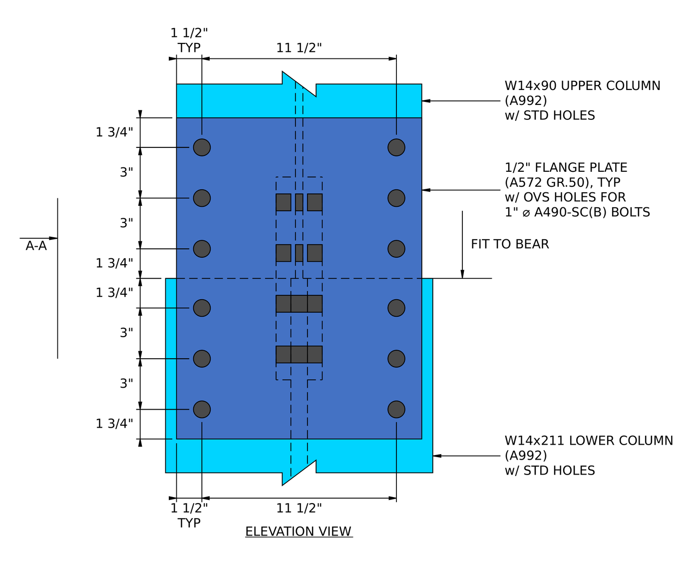
Elevation of the flange splice. NS 1/2 in flange plate has two bolt lines at an 11 1/2 ölçü olarak, 1 1/2 in in from each plate edge, and three bolt rows on each side of the joint at 3 aralıkta, ile 1 3/4 son mesafelerde. The column ends are fit to bear.
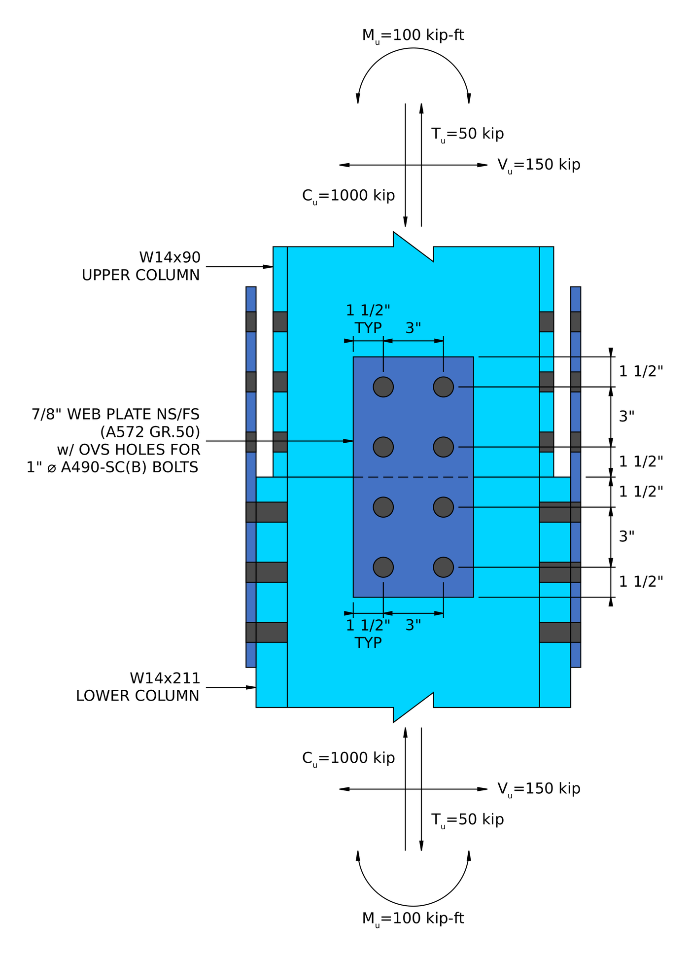
Bölüm A-A. NS 7/8 in web plates sit on both faces of the web (NS/FS), with two rows of two bolts on each side of the joint at 3 aralıkta ve 1 1/2 in edge and end distances. Shim plates fill every gap between the columns and the plates.
Column splice connection design: bir bakışta adımlar
First the loads are split: compression goes to bearing, and the moment, tension and shear go to the plates. Then the flange plate splice is checked at the lower column and at the upper column, followed by the web plate splice.
- Flanş plakası cıvatalarının detay sınırlarını kontrol edin.
- Find the filler factor and check slip of the slip-critical flange bolts.
- Flanş plakasındaki cıvata yatağını ve yırtılmayı kontrol edin.
- Kolon flanşındaki cıvata yatağını ve yırtılmayı kontrol edin.
- Üç yırtma modeli için flanş plakasının blok kesmesini kontrol edin.
- Check block shear of the column flange.
- Flanş plakasındaki gerginlik ve kopmayı kontrol edin.
- Check tension rupture of the column, kesme gecikmeli.
- Check flexural rupture of the column at the flange bolt holes.
- Flanş plakasını basınç altında kontrol edin.
- Repeat the flange checks for the upper column.
- Web plakası cıvatalarının detay sınırlarını kontrol edin.
- Kesme ve eksenel yükün bileşkesi altında gövde cıvata grubunun kaymasını kontrol edin.
- Ağ plakalarındaki cıvata yatağını kesme açısından kontrol edin, eksenel yük ve etkileşimleri.
- Check bolt bearing on the column web for shear, eksenel yük ve etkileşimleri.
- Gövde plakalarının blok kesmesini kesme açısından kontrol edin, eksenel yük ve etkileşimleri.
- Check block shear of the column web for axial load.
- Ağ plakalarının kesme akmasını ve kesme kopmasını kontrol edin.
- Ağ plakalarının gerilim esnekliğini ve kopmasını kontrol edin.
- Check tension rupture of the column web, kesme gecikmeli.
- Sıkıştırılmış ağ plakalarını kontrol edin.
- Repeat the web checks for the upper column.
Bu örnek için tasarım girdileri
Tasarım kodu AISC'dir 360-16 LRFD. Bölüm özellikleri AISC Kılavuzundan alınmıştır.
| Yük | Sembol | Değer |
|---|---|---|
| Factored shear | [mathin] V_{u} [mathin] | 150 kip |
| Faktörlü eksenel gerilim | [mathin] T_{u} [mathin] | 50 kip |
| Faktörlü eksenel sıkıştırma | [mathin] C_{u} [mathin] | 1000 kip |
| Faktörlü güçlü eksen momenti | [mathin] M_{u} [mathin] | 100 acı |
| Column property | Sembol | Lower column | Upper column |
|---|---|---|---|
| Bölüm | W14x211, A992 | W14x90, A992 | |
| ACI-Doğrulama-Kitaplar-Önizleme | [mathin] d [mathin] | 15.7 içinde | 14 içinde |
| Web kalınlığı | [mathin] t_{w} [mathin] | 0.98 içinde | 0.44 içinde |
| Flanş genişliği | [mathin] b_{f} [mathin] | 15.8 içinde | 14.5 içinde |
| Flanş kalınlığı | [mathin] t_{f} [mathin] | 1.56 içinde | 0.71 içinde |
| Alan | [mathin] A [mathin] | 62 inç² | 26.5 inç² |
| Plastic section modulus | [mathin] Z_{x} [mathin] | 390 inç³ | 157 inç³ |
| Teslim olmak / çekme gerilimi | [mathin] F_{y},\ F_{u} [mathin] | 50 ksi / 65 ksi | 50 ksi / 65 ksi |
| Flanş plakası ek yeri | Sembol | Lower column | Upper column |
|---|---|---|---|
| Flanş plakası genişliği / kalınlık | [mathin] b_{fp},\ t_{fp} [mathin] | 14.5 içinde / 0.5 içinde, A572 Gr. 50 | 14.5 içinde / 0.5 içinde, A572 Gr. 50 |
| Plaka verimi / çekme gerilimi | [mathin] F_{yp},\ F_{up} [mathin] | 50 ksi / 65 ksi | 50 ksi / 65 ksi |
| Cıvatalar | 1 A490-SC'de, B sınıfı, tek kayma düzlemi | 1 A490-SC'de, B sınıfı, tek kayma düzlemi | |
| Cıvata nominal gerilmesi / kayma gerilmesi | [mathin] F_{nt},\ F_{nv} [mathin] | 113 ksi / 68 ksi | 113 ksi / 68 ksi |
| Plakadaki delikler / sütun flanşı | Büyük boy (OV'ler) / liste yalnızca ABD'nin materyallerini içerir (STD) | Büyük boy (OV'ler) / liste yalnızca ABD'nin materyallerini içerir (STD) | |
| Cıvata hatları / ölçü | [mathin] n_{r},\ g_{a} [mathin] | 2 / 11.5 içinde | 2 / 11.5 içinde |
| Cıvata satırları / aralık | [mathin] n_{c},\ s_{c} [mathin] | 3 / 3 içinde | 3 / 3 içinde |
| Edge distance across the plate / sütun flanşı | [mathin] L_{ev,fp},\ L_{ev,c} [mathin] | 1.5 içinde / 2.125 içinde | 1.5 içinde / 1.5 içinde |
| End distance on plate / sütun flanşı | [mathin] L_{eh,fp},\ L_{eh,c} [mathin] | 1.75 içinde / 1.75 içinde | 1.75 içinde / 1.75 içinde |
| Unbraced length of plate | [mathin] L_{b} [mathin] | 3.5 içinde | 3.5 içinde |
| Web plakası ekleme | Sembol | Lower column | Upper column |
|---|---|---|---|
| Web plate width / kalınlık | [mathin] b_{wp},\ t_{wp} [mathin] | 6 içinde / 0.875 in each, A572 Gr. 50 | 6 içinde / 0.875 in each, A572 Gr. 50 |
| Cıvatalar | 1 A490-SC'de, B sınıfı, iki kayma düzlemi | 1 A490-SC'de, B sınıfı, iki kayma düzlemi | |
| Plakadaki delikler / column web | Büyük boy (OV'ler) / liste yalnızca ABD'nin materyallerini içerir (STD) | Büyük boy (OV'ler) / liste yalnızca ABD'nin materyallerini içerir (STD) | |
| Cıvata satırları / satır aralığı | [mathin] n_{r},\ s_{r} [mathin] | 2 / 3 içinde | 2 / 3 içinde |
| Cıvata sütunları / sütun aralığı | [mathin] n_{c},\ s_{c} [mathin] | 2 / 3 içinde | 2 / 3 içinde |
| Web plate vertical edge distance | [mathin] L_{ev,wp} [mathin] | 1.5 içinde | 1.5 içinde |
| End distance on web plate / column web | [mathin] L_{eh,wp},\ L_{eh,c} [mathin] | 1.5 içinde / 1.5 içinde | 1.5 içinde / 1.5 içinde |
| Web plate length on each side of the joint | [mathin] L_{wp} [mathin] | 6 içinde | 6 içinde |
| Unbraced length of plate | [mathin] L_{b} [mathin] | 3 içinde | 3 içinde |
In a column the bolts are laid out along the member, which is vertical. The report keeps the beam splice naming, yani “cıvata sütunları” of the flange splice are the three rows of bolts stacked up each column, ve “yatay” edge distance is the end distance to the plate end or the column end.
The edge distances across the flange come from the gage. NS 14.5 in plate with an 11.5 in gage leaves [mathin] (14.5 – 11.5)/2 = 1.5\,in [mathin] on each side, and so does the 14.5 in flange of the W14x90. The lower column uses the W14x211 detailing flange width of 15 3/4 içinde, Bu yüzden [mathin] L_{ev,c} = (15.75 – 11.5)/2 = 2.125\,in [mathin].
How the loads are split in a column splice
The column ends are milled and fit to bear, which is the note on the elevation. AISC 360-16 J1.4 allows compression to pass through a finished bearing joint, so the splice plates do not need to carry it. The bearing strength of the milled surface uses J7, with the bearing area of the smaller column:
[math] C_{u,brg} = \min\left( C_{u},\, \phi\, 1.8\, F_{y}\, A_{brg} \right) = \min\left( (1000\,kip),\, (0.75) \times 1.8 \times (50\,ksi) \times (26.125\,in^{2}) \right) = 1000\,kip [math]
The bearing area of 26.125 in² is the two flanges and the web of the W14x90 from its nominal dimensions, [mathin] 2 \times 14.5 \times 0.71 + (14 – 2 \times 0.71) \times 0.44 = 26.125\,in^{2} [mathin], so it leaves out the fillets that the 26.5 in² tabulated area includes. Herşey 1000 kip of compression goes into bearing, so the compression left for the web plates is zero:
[math] C_{web} = 0\,kip [math]
The moment is turned into a flange force couple using the lever arm of the shallower upper column, [mathin] d – t_{f} = 14 – 0.71 = 13.29\,in [mathin]. The compression flange force is only the moment couple, because no compression is left over from bearing:
[math] C_{flange} = \frac{C_{u} – C_{u,brg} – C_{web}}{2} + \frac{M_{u}}{d_{uc} – t_{f,uc}} = \frac{(1000\,kip) – (1000\,kip) – (0\,kip)}{2} + \frac{(100\,kip\text{-}ft)}{(14\,in) – (0.71\,in)} = 90.293\,kip [math]
Tension cannot pass through bearing, so it is shared between the flanges and the web. The web takes the share of the 50 kip proportioned to the web area over the gross area, [mathin] T_{web} = 9.9423\,kip [mathin], ve flanşlar gerisini alır, her birinin yarısı:
[math] T_{flange} = \frac{T_{u} – T_{web}}{2} + \frac{M_{u}}{d_{uc} – t_{f,uc}} = \frac{(50\,kip) – (9.9423\,kip)}{2} + \frac{(100\,kip\text{-}ft)}{(14\,in) – (0.71\,in)} = 110.32\,kip [math]
[math] P_{flange} = \max\left( T_{flange},\, C_{flange} \right) = \max\left( (110.32\,kip),\, (90.293\,kip) \right) = 110.32\,kip [math]
The web plates carry the full shear plus the web share of the tension. Their resultant is used for the web bolt slip check:
[math] P_{web} = 9.9423\,kip, \quad R_{u} = \sqrt{V_{u}^{2} + P_{web}^{2}} = \sqrt{(150\,kip)^{2} + (9.9423\,kip)^{2}} = 150.33\,kip [math]
Bearing makes a large difference here. Without it, each flange plate would have to carry half of the 1000 kip on top of the moment couple, which this 1/2 in plate and six bolts could not do. The fit-to-bear note on the drawing is part of the design, not a fabrication detail.
Bölüm 1: Flange plate splice at the lower column
Adım 1: Flanş plakası cıvatalarının detaylandırma sınırları (AISC 360-16 J3.3, J3.4, J3.5)
The flange bolts must be spaced far enough apart to tighten and close enough together to act as a group, and every bolt needs enough edge distance on both the plate and the column flange.
The plate has oversized holes, yani Tablo J3.5 şunu ekliyor: 1/8 in to the Table J3.4 minimum edge distance of 1.25 içinde, verme 1.375 in on the plate. The column flange has standard holes and keeps 1.25 içinde.
| Detaylandırma sınırı | Sınır (içinde) | Gerçek (içinde) | DCR | Sonuç |
|---|---|---|---|---|
| Minimum cıvata ölçüsü | 5.375 | 11.500 | 0.467 | GEÇMEK |
| Minimum cıvata sıra aralığı | 2.667 | 3.000 | 0.889 | GEÇMEK |
| Maksimum cıvata sırası aralığı | 6.000 | 3.000 | 0.500 | GEÇMEK |
| Flange plate minimum edge distance, across | 1.375 | 1.500 | 0.917 | GEÇMEK |
| Flange plate minimum end distance | 1.375 | 1.750 | 0.786 | GEÇMEK |
| Column flange minimum edge distance, across | 1.250 | 2.125 | 0.588 | GEÇMEK |
| Column flange minimum end distance | 1.250 | 1.750 | 0.714 | GEÇMEK |
DCR = 1.375 içinde / 1.5 içinde = 0.917 < 1.0, TAMAM MI
The edge distance across the flange plate governs. With an 11.5 in gage on a 14.5 tabakta, each bolt line sits 1.5 in from the plate edge, sadece 1/8 in more than the oversized-hole minimum.
Adım 2: Slip-critical bolt strength at the flange (AISC 360-16 J3.8, Manual Table 14-3)
The plates have oversized holes, hangi AISC 360-16 J3.2 allows only in slip-critical joints. The bolt group must resist the flange force by friction, without slipping into bearing. Fillers between the plate and the column reduce slip resistance, so the filler thickness is found first.
Filler thickness and filler factor
The detailing depths are [mathin] d_{det,lc} = 15.75\,in [mathin] for the W14x211 and [mathin] d_{det,uc} = 14\,in [mathin] for the W14x90, the depths rounded to the nearest 1/16 in that the AISC Manual lists for detailing. The flange plates lie flat on the deeper lower column, so on this side the filler is zero (Manual Table 14-3, Cases I-A and I-B):
[math] t_{f} = \left\lceil \frac{\max\left( d_{det,uc} – d_{det,lc},\, 0 \right)}{2} + 0.125\,in \right\rceil_{0.125\,in} \text{ if } d_{det,lc} – d_{det,uc} \lt 0.25\,in, \text{ otherwise } 0 [math]
[math] t_{f} = 0\,in, \quad h_{f} = 1.0 [math]
With no filler, the filler factor [mathin] h_{f} [mathin] dır-dir 1.0.
Kayma direnci
Nerede [mathin] \phi = 0.85 [mathin] büyük boyutlu delikler için, [mathin] \mu = 0.5 [mathin] for Class B faying surfaces, [mathin] D_{u} = 1.13 [mathin], [mathin] T_{b} = 64\,kip [mathin] bir için 1 A490 cıvatasında, [mathin] N_{s} = 1 [mathin] kayma düzlemi, ve 2 bolt lines by 3 bolt rows:
[math] \phi R_{n} = \phi\, \mu\, D_{u}\, h_{f}\, T_{b}\, N_{s}\, n_{r}\, n_{c} [math]
[math] \phi R_{n} = (0.85) \times (0.5) \times (1.13) \times (1) \times (64\,kip) \times (1) \times (2) \times (3) [math]
[math] \phi R_{n} = 184.42\,kip [math]
DCR = 110.32 kip / 184.42 kip = 0.598 < 1.0, TAMAM MI
Adım 3: Flanş plakasında cıvata yatağı ve yırtılma (AISC 360-16 J3.10)
Each bolt bears on the side of its hole in the plate. The end bolt can tear out toward the plate end, and the others toward the hole in front of them. In an oversized hole the hole dimension is [mathin] d_{h} = 1.25\,in [mathin]:
[math] l_{c1} = L_{eh,fp} – \frac{d_{h}}{2} = (1.75\,in) – \frac{(1.25\,in)}{2} = 1.125\,in, \quad l_{c2} = s_{c} – d_{h} = (3\,in) – (1.25\,in) = 1.75\,in [math]
Nerede [mathin] t_{fp} = 0.5\,in [mathin], [mathin] F_{up} = 65\,ksi [mathin] ve [mathin] \phi = 0.75 [mathin]:
[math] \phi R_{n} = \phi \left[ \min\left(1.2\, l_{c1},\, 2.4\, d_{b}\right) t_{fp} F_{up}\, n_{r} + \min\left(1.2\, l_{c2},\, 2.4\, d_{b}\right) t_{fp} F_{up}\, n_{r} \left( n_{c} – 1 \right) \right] [math]
[math] \phi R_{n} = (0.75) \times \left[ \min\left(1.2 \times 1.125\,in,\, 2.4\,in\right)(0.5\,in)(65\,ksi)(2) + \min\left(1.2 \times 1.75\,in,\, 2.4\,in\right)(0.5\,in)(65\,ksi)(2)(3 – 1) \right] [math]
[math] \phi R_{n} = 270.56\,kip [math]
DCR = 110.32 kip / 270.56 kip = 0.408 < 1.0, TAMAM MI
Adım 4: Kolon flanşında cıvata yatağı ve yırtılma (AISC 360-16 J3.10)
The same check on the column flange uses standard holes, [mathin] d_{h} = 1.125\,in [mathin], ve 1.56 in thick flange of the W14x211:
[math] l_{c1} = L_{eh,c} – \frac{d_{h}}{2} = (1.75\,in) – \frac{(1.125\,in)}{2} = 1.1875\,in, \quad l_{c2} = s_{c} – d_{h} = (3\,in) – (1.125\,in) = 1.875\,in [math]
[math] \phi R_{n} = (0.75) \times \left[ \min\left(1.2 \times 1.1875\,in,\, 2.4\,in\right)(1.56\,in)(65\,ksi)(2) + \min\left(1.2 \times 1.875\,in,\, 2.4\,in\right)(1.56\,in)(65\,ksi)(2)(3 – 1) \right] [math]
[math] \phi R_{n} = 901.19\,kip [math]
DCR = 110.32 kip / 901.19 kip = 0.122 < 1.0, TAMAM MI
The lower column flange is more than three times the thickness of the plate, so bearing on the column is not a concern on this side.
Adım 5: Flanş plakasının blok kesmesi (AISC 360-16 J4.3)
A block of the flange plate can tear out around the bolts: shear along the bolt lines to the plate end, and tension across the plate. The report checks three patterns and takes the lowest. In each, the hole size for net area is [mathin] d_{h} + 1/16\,in [mathin].
L deseni
One shear plane along a bolt line, and tension across from that line to the far plate edge:
[math] A_{nt} = t_{fp} \left[ (n_{r} – 2)\, s_{r} + g_{a} + L_{ev,fp} – (n_{r} – 0.5)\left( d_{h} + 0.0625\,in \right) \right] = (0.5\,in) \times \left[ 0 + 11.5\,in + 1.5\,in – 1.5(1.3125\,in) \right] = 5.5156\,in^{2} [math]
[math] A_{gv} = t_{fp} \left[ L_{eh,fp} + (n_{c} – 1)\, s_{c} \right] = (0.5\,in) \times \left[ 1.75\,in + 2(3\,in) \right] = 3.875\,in^{2} [math]
[math] A_{nv} = t_{fp} \left[ L_{eh,fp} + (n_{c} – 1)\, s_{c} – (n_{c} – 0.5)\left( d_{h} + 0.0625\,in \right) \right] = (0.5\,in) \times \left[ 7.75\,in – 2.5(1.3125\,in) \right] = 2.2344\,in^{2} [math]
[math] \phi R_{n} = \phi \left( 0.6\, F_{up}\, A_{nv} + U_{bs}\, F_{up}\, A_{nt} \right) \le \phi \left( 0.6\, F_{yp}\, A_{gv} + U_{bs}\, F_{up}\, A_{nt} \right) [math]
[math] \phi R_{n} = (0.75) \left( 0.6 \times 65 \times 2.2344 + 1 \times 65 \times 5.5156 \right) \le (0.75) \left( 0.6 \times 50 \times 3.875 + 1 \times 65 \times 5.5156 \right) = 334.24\,kip [math]
U deseni
Two shear planes along both bolt lines, and tension across the gage between them:
[math] A_{gv} = 2t_{fp} \left[ L_{eh,fp} + (n_{c} – 1)\, s_{c} \right] = 7.75\,in^{2}, \quad A_{nv} = 4.4687\,in^{2} [math]
[math] A_{nt} = t_{fp} \left[ (n_{r} – 2)\, s_{r} + g_{a} – (n_{r} – 1)\left( d_{h} + 0.0625\,in \right) \right] = (0.5\,in) \times \left[ 11.5\,in – 1.3125\,in \right] = 5.0938\,in^{2} [math]
[math] \phi R_{n} = (0.75) \left( 0.6 \times 65 \times 4.4687 + 1 \times 65 \times 5.0938 \right) \le (0.75) \left( 0.6 \times 50 \times 7.75 + 1 \times 65 \times 5.0938 \right) = 379.03\,kip [math]
2L deseni
Two shear planes along both bolt lines, and tension from each line out to its own plate edge:
[math] A_{nt} = 2t_{fp} \left[ L_{ev,fp} – 0.5\left( d_{h} + 0.0625\,in \right) \right] = (1\,in) \times \left[ 1.5\,in – 0.5(1.3125\,in) \right] = 0.84375\,in^{2} [math]
[math] \phi R_{n} = (0.75) \left( 0.6 \times 65 \times 4.4687 + 1 \times 65 \times 0.84375 \right) \le (0.75) \left( 0.6 \times 50 \times 7.75 + 1 \times 65 \times 0.84375 \right) = 171.84\,kip [math]
[math] \phi R_{n} = \min\left( 334.24\,kip,\, 379.03\,kip,\, 171.84\,kip \right) = 171.84\,kip [math]
DCR = 110.32 kip / 171.84 kip = 0.642 < 1.0, TAMAM MI
The 2L pattern governs. The wide 11.5 in gage puts a lot of tension area between the bolt lines, which helps the L and U patterns, but it leaves only a 1.5 in strip outside each line. After the half hole comes out, the 2L block has less than 0.85 in² of net tension area.
Adım 6: Block shear of the column flange (AISC 360-16 J4.3)
The column flange can tear out the same way. Its edges are the flange tips, so the 2L pattern applies: shear along both bolt lines to the column end, and tension from each bolt line out to the flange tip.
[math] A_{nt} = t_{f,lc} \left[ b_{f,lc} – g_{a} – (n_{r} – 1)\left( d_{h} + 0.0625\,in \right) \right] = (1.56\,in) \times \left[ 15.8\,in – 11.5\,in – 1.1875\,in \right] = 4.8555\,in^{2} [math]
[math] A_{gv} = 2t_{f,lc} \left[ L_{eh,c} + (n_{c} – 1)\, s_{c} \right] = 2 \times (1.56\,in) \times \left[ 1.75\,in + 2(3\,in) \right] = 24.18\,in^{2} [math]
[math] A_{nv} = 2t_{f,lc} \left[ L_{eh,c} + (n_{c} – 1)\, s_{c} – (n_{c} – 0.5)\left( d_{h} + 0.0625\,in \right) \right] = 14.918\,in^{2} [math]
[math] \phi R_{n} = (0.75) \left( 0.6 \times 65 \times 14.918 + 1 \times 65 \times 4.8555 \right) \le (0.75) \left( 0.6 \times 50 \times 24.18 + 1 \times 65 \times 4.8555 \right) = 673.04\,kip [math]
DCR = 110.32 kip / 673.04 kip = 0.164 < 1.0, TAMAM MI
Adım 7: Flanş plakasının gerilmesi ve kopması (AISC 360-16 J4.1)
The flange plate carries the full flange force across the joint, so its gross section must not yield and its net section through the two holes must not rupture.
[math] \phi R_{n,ty} = \phi\, F_{yp}\, t_{fp}\, b_{fp} = (0.9) \times (50\,ksi) \times (0.5\,in) \times (14.5\,in) = 326.25\,kip [math]
[math] \phi R_{n,tr} = \phi\, F_{up}\, t_{fp} \left[ b_{fp} – n_{r}\left( d_{h} + 0.0625\,in \right) \right] = (0.75) \times (65\,ksi) \times (0.5\,in) \times \left[ 14.5\,in – 2 \times (1.3125\,in) \right] = 289.45\,kip [math]
[math] \phi R_{n} = \min\left( 326.25\,kip,\, 289.45\,kip \right) = 289.45\,kip [math]
DCR = 110.32 kip / 289.45 kip = 0.381 < 1.0, TAMAM MI
Adım 8: Tension rupture of the column, kesme gecikmeli (AISC 360-16 D3, J4.1)
The flange force also has to get into the column. Only the flange is bolted, so the report treats half the column as a tee and applies shear lag from Table D3.1, Durum 2. The tee’s centroid is [mathin] \bar{y} = 1.5842\,in [mathin] from the outside of the flange, and the connection length is [mathin] l = (n_{c} – 1)\, s_{c} = 6\,in [mathin]:
[math] U = 1 – \frac{\bar{y}}{l} = 1 – \frac{1.5842\,in}{6\,in} = 0.73606 [math]
[math] \phi R_{n} = \phi\, F_{u}\, U \left[ 0.5\, A_{lc} – n_{r}\left( d_{h} + 0.0625\,in \right) t_{f,lc} \right] = (0.75) \times (65\,ksi) \times (0.73606) \times \left[ 0.5 \times (62\,in^{2}) – 2 \times (1.1875\,in) \times (1.56\,in) \right] [math]
[math] \phi R_{n} = 979.43\,kip [math]
DCR = 110.32 kip / 979.43 kip = 0.113 < 1.0, TAMAM MI
Three bolt rows give a 6 bağlantı uzunluğunda, so the shear lag factor drops to about 0.74. A short connection on a deep tee loses more of its net area to shear lag than a long one.
Adım 9: Flexural rupture of the column at the bolt holes (AISC 360-16 F13.1)
The bolt holes in the tension flange can reduce the column’s flexural strength. F13.1 compares the rupture strength of the net flange with the yield strength of the gross flange to decide whether they do.
[math] A_{fg} = b_{f,lc}\, t_{f,lc} = (15.8\,in) \times (1.56\,in) = 24.648\,in^{2} [math]
[math] A_{fn} = A_{fg} – n_{r}\left( d_{h} + 0.0625\,in \right) t_{f,lc} = (24.648\,in^{2}) – 2 \times (1.1875\,in) \times (1.56\,in) = 20.943\,in^{2} [math]
The ratio [mathin] F_{y}/F_{u} = 50/65 = 0.76923 [mathin] is not more than 0.8, Bu yüzden [mathin] Y_{t} = 1.0 [mathin]:
[math] F_{u}\, A_{fn} = (65\,ksi) \times (20.943\,in^{2}) = 1361.3\,kip \ge Y_{t}\, F_{y}\, A_{fg} = (1) \times (50\,ksi) \times (24.648\,in^{2}) = 1232.4\,kip [math]
Çünkü [mathin] F_{u} A_{fn} [mathin] daha az değil [mathin] Y_{t} F_{y} A_{fg} [mathin], the limit state of tensile rupture does not apply, and the holes do not limit flexure. The column keeps its plastic moment:
[math] M_{n} = F_{y}\, Z_{x} = (50\,ksi) \times (390\,in^{3}) = 1625\,kip\text{-}ft [math]
That moment is converted to a flange force over the column’s own lever arm, so it can be compared with the flange force:
[math] \phi R_{n} = \frac{\phi\, M_{n}}{d_{lc} – t_{f,lc}} = \frac{(0.9) \times (1625\,kip\text{-}ft)}{(15.7\,in) – (1.56\,in)} = 1241.2\,kip [math]
DCR = 110.32 kip / 1241.2 kip = 0.089 < 1.0, TAMAM MI
Adım 10: Flanş plakasının sıkıştırma mukavemeti (AISC 360-16 J4.4, E3)
On the compression side of the moment, the flange plate spans between the nearest bolts above and below the joint as a short column. Its compression demand is the 90.293 kip moment couple from the load split, because the axial compression goes through bearing.
İle [mathin] K = 1.2 [mathin], [mathin] L_{b} = 3.5\,in [mathin] ve [mathin] r = t_{fp}/\sqrt{12} [mathin]:
[math] \frac{K L}{r} = \frac{(1.2) \times (3.5\,in)}{(0.5\,in) / \sqrt{12}} = 29.098 \gt 25 [math]
KL/r yukarıda 25, so J4.4 sends the plate to Chapter E. İncelik aşağıda [mathin] 4.71\sqrt{E/F_{y}} = 113.43 [mathin], yani Denklem. E3-2 geçerlidir:
[math] F_{e} = \frac{\pi^{2} E}{\left( KL/r \right)^{2}} = \frac{\pi^{2} \times (29000\,ksi)}{(29.098)^{2}} = 338.03\,ksi [math]
[math] F_{cr} = 0.658^{F_{yp}/F_{e}} F_{yp} = 0.658^{(50/338.03)} \times (50\,ksi) = 46.998\,ksi [math]
[math] \phi R_{n} = \phi\, F_{cr}\, t_{fp}\, b_{fp} = (0.9) \times (46.998\,ksi) \times (0.5\,in) \times (14.5\,in) = 306.66\,kip [math]
DCR = 90.293 kip / 306.66 kip = 0.294 < 1.0, TAMAM MI
Buckling takes only about 6% off the yield stress at this slenderness. A thinner plate or a longer unbraced length would cost more, because r drops with the plate thickness.
Adım 11: Flange plate splice at the upper column
The same flange plate and bolt layout are used on the W14x90, yani plaka kontrol ediliyor (bearing on the plate, block shear of the plate, plate tension and plate compression) give the same results as at the lower column. Three things change: the column flange is thinner at 0.71 içinde, the minimum gage drops to 4.875 içinde, and there is now a filler.
Filler on the upper column
The W14x90 is 1.75 in shallower than the W14x211, so the flange plates stand off its flanges and need a filler on each side. The report sizes it with Manual Table 14-3, Cases I-A and I-C:
[math] t_{f} = \left\lfloor \frac{d_{det,lc} – d_{det,uc}}{2} – 0.125\,in \right\rfloor_{0.125\,in} \text{ if } d_{det,lc} – d_{det,uc} \gt 0.625\,in, \text{ otherwise } 0 [math]
[math] t_{f} = 0.625\,in [math]
Any filler thicker than 1/8 in drops the filler factor to 0.85, which takes 15% off the slip resistance:
[math] h_{f} = 1.0 \text{ if } t_{f} \le 0.125\,in, \text{ otherwise } 0.85 \quad \Rightarrow \quad h_{f} = 0.85 [math]
[math] \phi R_{n} = (0.85) \times (0.5) \times (1.13) \times (0.85) \times (64\,kip) \times (1) \times (2) \times (3) = 156.75\,kip [math]
DCR = 110.32 kip / 156.75 kip = 0.704 < 1.0, TAMAM MI
This is the highest flange strength check. The same six bolts have a DCR of 0.598 at the lower column and 0.704 at the upper column, and the only difference is the filler factor.
Other checks at the upper column
| Soğuk şekillendirilmiş elemanlar aşağıdakilere uygun olarak tasarlanırken | Anahtar değerler | Kapasite | DCR |
|---|---|---|---|
| Detaylandırma sınırları | Minimum gage 4.875 içinde (0.424), column flange edge distance 1.5 içinde (0.833) | 1.375 sınırda, 1.5 in actual | 0.917 |
| Bearing on column flange | [mathin] t_{f,uc} = 0.71\,in,\ l_{c1} = 1.1875\,in,\ l_{c2} = 1.875\,in [mathin] | 410.16 kip | 0.269 |
| Block shear of column flange | [mathin] A_{nt} = 1.2869,\ A_{gv} = 11.005,\ A_{nv} = 6.7894\,in^{2} [mathin] | 261.32 kip | 0.422 |
| Column tension rupture | [mathin] \bar{y} = 1.1356\,in,\ U = 0.81081,\ A = 26.5\,in^{2} [mathin] | 457.08 kip | 0.241 |
| Column flexural rupture | [mathin] F_{u}A_{fn} = 559.57 \ge F_{y}A_{fg} = 514.75\,kip,\ M_{n} = 654.17\,kip\text{-}ft [mathin] | 531.60 kip | 0.208 |
The W14x90 flange is the same 14.5 in width as the plate, so its edge distance is also 1.5 içinde. The column flange has standard holes and a 1.25 asgari olarak, so its ratio is 0.833. The flange plate edge distance still governs the detailing at 0.917.
Block shear of the column flange is the highest column check on this side at 0.422. The 2L tension strip on the W14x90 is only 1.5 in wide on each side and 0.71 kalın.
Bölüm 2: Web plate splice at the lower column
Adım 12: Web plakası cıvataları için detaylandırma sınırları (AISC 360-16 J3.3, J3.4, J3.5)
Web cıvatası düzeni, flanşla aynı aralık ve kenar mesafesi kurallarını karşılamalıdır., and the web plates have to be deep enough to meet the minimum connection depth but still fit between the column flanges.
| Detaylandırma sınırı | Sınır (içinde) | Gerçek (içinde) | DCR | Sonuç |
|---|---|---|---|---|
| Minimum cıvata sıra aralığı | 2.667 | 3.000 | 0.889 | GEÇMEK |
| Maksimum cıvata sırası aralığı | 6.000 | 3.000 | 0.500 | GEÇMEK |
| Minimum cıvata sütun aralığı | 2.667 | 3.000 | 0.889 | GEÇMEK |
| Maksimum cıvata sütun aralığı | 6.000 | 3.000 | 0.500 | GEÇMEK |
| Web plate minimum vertical edge distance | 1.375 | 1.500 | 0.917 | GEÇMEK |
| Web plate minimum horizontal edge distance | 1.375 | 1.500 | 0.917 | GEÇMEK |
| Minimum bağlantı derinliği | 5.000 | 6.000 | 0.833 | GEÇMEK |
| Maksimum bağlantı derinliği | 10.000 | 6.000 | 0.600 | GEÇMEK |
DCR = 1.375 içinde / 1.5 içinde = 0.917 < 1.0, TAMAM MI
Both web plate edge distances are 1.5 in against the oversized-hole minimum of 1.375 içinde. NS 6 in plate is exactly 1.5 + 3 + 1.5 içinde, so there is no spare width.
Adım 13: Slip-critical bolt strength at the web (AISC 360-16 J3.8)
The web bolts carry the shear and the web tension together, yani kayma kontrolü onların sonucunu kullanır, 150.33 kip. The bolts are slip-critical because the web plates have oversized holes.
The lower column web is the thicker one, so there is no filler on this side. Using the detailing web thicknesses, 7/16 in for the W14x90 and 1 in for the W14x211:
[math] t_{f} = \max\left( \frac{tw_{det,uc} – tw_{det,lc}}{2},\, 0 \right) = \max\left( \frac{(0.4375\,in) – (1\,in)}{2},\, 0 \right) = 0\,in, \quad h_{f} = 1 [math]
Nerede [mathin] \phi = 0.85 [mathin], [mathin] \mu = 0.5 [mathin], [mathin] D_{u} = 1.13 [mathin], [mathin] T_{b} = 64\,kip [mathin], ve [mathin] N_{s} = 2 [mathin] kayma düzlemleri çünkü ağın her yüzünde bir ağ plakası vardır:
[math] \phi R_{n} = \phi\, \mu\, D_{u}\, h_{f}\, T_{b}\, N_{s}\, n_{r}\, n_{c} = (0.85) \times (0.5) \times (1.13) \times (1) \times (64\,kip) \times (2) \times (2) \times (2) = 245.89\,kip [math]
DCR = 150.33 kip / 245.89 kip = 0.611 < 1.0, TAMAM MI
Adım 14: Ağ plakalarındaki cıvata yatağı (AISC 360-16 J3.10)
Ağ plakası delikleri aynı anda iki yönde yüklenir: across the column by the shear, and along the column by the web tension. Bearing and tear-out are checked separately in each direction and then combined. Her iki plaka birlikte çalışır, yani kalınlık [mathin] 2t_{wp} = 1.75\,in [mathin], and the bolt group coefficient is [mathin] C = 4 [mathin] because the load is concentric.
Kesme yönü
[math] l_{c1} = L_{ev,wp} – \frac{d_{h}}{2} = (1.5\,in) – \frac{(1.25\,in)}{2} = 0.875\,in, \quad l_{c2} = s_{r} – d_{h} = (3\,in) – (1.25\,in) = 1.75\,in [math]
[math] \phi R_{n} = \phi \left[ \min\left(1.2\, l_{c1},\, 2.4\, d_{b}\right) 2t_{wp} F_{up} + \min\left(1.2\, l_{c2},\, 2.4\, d_{b}\right) 2t_{wp} F_{up} \left( n_{r} – 1 \right) \right] \frac{C}{n_{r}} [math]
[math] \phi R_{n} = (0.75) \times \left[ \min\left(1.05\,in,\, 2.4\,in\right)(1.75\,in)(65\,ksi) + \min\left(2.1\,in,\, 2.4\,in\right)(1.75\,in)(65\,ksi)(2 – 1) \right] \times \frac{4}{2} = 537.47\,kip [math]
DCR = 150 kip / 537.47 kip = 0.279 < 1.0, TAMAM MI
Eksenel yön
The end distance on the web plate is also 1.5 içinde, so the clear distances and the strength are the same as in the shear direction:
[math] l_{c1} = L_{eh,wp} – \frac{d_{h}}{2} = (1.5\,in) – \frac{(1.25\,in)}{2} = 0.875\,in, \quad l_{c2} = s_{c} – d_{h} = 1.75\,in, \quad \phi R_{n} = 537.47\,kip [math]
DCR = 9.9423 kip / 537.47 kip = 0.018 < 1.0, TAMAM MI
Etkileşim
[math] \left( \frac{V_{u}}{\phi R_{n,v}} \right)^{2} + \left( \frac{P_{web}}{\phi R_{n,a}} \right)^{2} = \left( \frac{150}{537.47} \right)^{2} + \left( \frac{9.9423}{537.47} \right)^{2} = 0.078231 [math]
DCR = 0.078 < 1.0, TAMAM MI
Adım 15: Bolt bearing on the column web (AISC 360-16 J3.10)
The column web has standard holes, [mathin] d_{h} = 1.125\,in [mathin], ve 0.98 in thick on the W14x211.
Kesme yönü
Across the column there is web on both sides of the bolts, böylece her cıvata delikler arasındaki net mesafeyi kullanır, [mathin] l_{c2} = 3 – 1.125 = 1.875\,in [mathin]:
[math] \phi R_{n} = \phi \min\left(1.2\, l_{c2},\, 2.4\, d_{b}\right) t_{w,lc}\, F_{u,lc}\, C = (0.75) \times \min\left(2.25\,in,\, 2.4\,in\right) \times (0.98\,in) \times (65\,ksi) \times (4) = 429.98\,kip [math]
DCR = 150 kip / 429.98 kip = 0.349 < 1.0, TAMAM MI
Eksenel yön
Along the column, the bolt row nearest the column end tears out toward it, ile [mathin] l_{c1} = L_{eh,c} – d_{h}/2 = 1.5 – 0.5625 = 0.9375\,in [mathin]:
[math] \phi R_{n} = (0.75) \times \left[ \min\left(1.125\,in,\, 2.4\,in\right)(0.98\,in)(65\,ksi) + \min\left(2.25\,in,\, 2.4\,in\right)(0.98\,in)(65\,ksi)(2 – 1) \right] \times \frac{4}{2} = 322.48\,kip [math]
DCR = 9.9423 kip / 322.48 kip = 0.031 < 1.0, TAMAM MI
Etkileşim
[math] \left( \frac{150}{429.98} \right)^{2} + \left( \frac{9.9423}{322.48} \right)^{2} = 0.12265 [math]
DCR = 0.123 < 1.0, TAMAM MI
Adım 16: Gövde plakalarının blok kesmesi (AISC 360-16 J4.3)
A block of the web plates can tear out under the shear or under the axial force. Each direction has its own tear-out pattern, ve iki oran, rulmanla aynı şekilde birleştirilir.
Kesme yükü
The block shears along the outer bolt row to the plate edge and tears in tension across the bolt columns to the plate end:
[math] A_{nt} = 2t_{wp} \left[ (n_{c} – 1)\, s_{c} + L_{eh,wp} – (n_{c} – 0.5)\left( d_{h} + 0.0625\,in \right) \right] = (1.75\,in) \times \left[ 3\,in + 1.5\,in – 1.5(1.3125\,in) \right] = 4.4297\,in^{2} [math]
[math] A_{gv} = 2t_{wp} \left[ L_{ev,wp} + (n_{r} – 1)\, s_{r} \right] = (1.75\,in) \times \left[ 1.5\,in + 3\,in \right] = 7.875\,in^{2} [math]
[math] A_{nv} = 2t_{wp} \left[ b_{wp} – L_{ev,wp} – (n_{r} – 0.5)\left( d_{h} + 0.0625\,in \right) \right] = (1.75\,in) \times \left[ 6\,in – 1.5\,in – 1.5(1.3125\,in) \right] = 4.4297\,in^{2} [math]
İki cıvatalı kolonla blok boyunca çekme gerilimi eşit değildir, Bu yüzden [mathin] U_{bs} = 0.5 [mathin]:
[math] \phi R_{n} = (0.75) \left( 0.6 \times 65 \times 4.4297 + 0.5 \times 65 \times 4.4297 \right) \le (0.75) \left( 0.6 \times 50 \times 7.875 + 0.5 \times 65 \times 4.4297 \right) = 237.54\,kip [math]
DCR = 150 kip / 237.54 kip = 0.631 < 1.0, TAMAM MI
Eksenel yük
L modelinde, the block tears in tension across the bolt rows and out the plate edge, and shears along one bolt row to the plate end:
[math] A_{nt} = 4.4297\,in^{2}, \quad A_{gv} = 2t_{wp} \left[ L_{eh,wp} + (n_{c} – 1)\, s_{c} \right] = 7.875\,in^{2}, \quad A_{nv} = 2t_{wp} \left[ L_{wp} – L_{eh,c} – (n_{c} – 0.5)\left( d_{h} + 0.0625\,in \right) \right] = 4.4297\,in^{2} [math]
[math] \phi R_{n,L} = (0.75) \left( 0.6 \times 65 \times 4.4297 + 1 \times 65 \times 4.4297 \right) \le (0.75) \left( 0.6 \times 50 \times 7.875 + 1 \times 65 \times 4.4297 \right) = 345.52\,kip [math]
U'da (veya C) model, the block between the two bolt rows pulls out, shearing along both rows:
[math] A_{nt} = 2t_{wp} \left[ (n_{r} – 1)\, s_{r} – (n_{r} – 1)\left( d_{h} + 0.0625\,in \right) \right] = (1.75\,in) \times \left[ 3\,in – 1.3125\,in \right] = 2.9531\,in^{2}, \quad A_{gv} = 15.75\,in^{2}, \quad A_{nv} = 8.8594\,in^{2} [math]
[math] \phi R_{n,U} = (0.75) \left( 0.6 \times 65 \times 8.8594 + 1 \times 65 \times 2.9531 \right) \le (0.75) \left( 0.6 \times 50 \times 15.75 + 1 \times 65 \times 2.9531 \right) = 403.1\,kip [math]
[math] \phi R_{n} = \min\left( 345.52\,kip,\, 403.1\,kip \right) = 345.52\,kip [math]
DCR = 9.9423 kip / 345.52 kip = 0.029 < 1.0, TAMAM MI
Etkileşim
[math] \left( \frac{150}{237.54} \right)^{2} + \left( \frac{9.9423}{345.52} \right)^{2} = 0.39958 [math]
DCR = 0.400 < 1.0, TAMAM MI
Almost all of the 0.400 comes from the shear term. The axial term adds about 0.001.
Adım 17: Block shear of the column web (AISC 360-16 J4.3)
Eksenel gerilim altında, a block of the column web around the bolts can pull out of the column end: tension between the two bolt rows, and shear along both rows to the end of the column. Bu C modelidir.
[math] A_{nt} = t_{w,lc} \left[ (n_{r} – 1)\, s_{r} – (n_{r} – 1)\left( d_{h} + 0.0625\,in \right) \right] = (0.98\,in) \times \left[ 3\,in – 1.1875\,in \right] = 1.7762\,in^{2} [math]
[math] A_{gv} = 2t_{w,lc} \left[ L_{eh,c} + (n_{c} – 1)\, s_{c} \right] = 2 \times (0.98\,in) \times \left[ 1.5\,in + 3\,in \right] = 8.82\,in^{2} [math]
[math] A_{nv} = 2t_{w,lc} \left[ (n_{c} – 1)\, s_{c} + L_{eh,c} – (n_{c} – 0.5)\left( d_{h} + 0.0625\,in \right) \right] = 5.3288\,in^{2} [math]
[math] \phi R_{n} = (0.75) \left( 0.6 \times 65 \times 5.3288 + 1 \times 65 \times 1.7762 \right) \le (0.75) \left( 0.6 \times 50 \times 8.82 + 1 \times 65 \times 1.7762 \right) = 242.46\,kip [math]
DCR = 9.9423 kip / 242.46 kip = 0.041 < 1.0, TAMAM MI
Adım 18: Ağ plakalarının kesme akması ve kesme kopması (AISC 360-16 J4.2)
İki ağ plakası tam yükü taşır 150 ek yeri boyunca kip kesme. Brüt kesitleri kesme sırasında akmamalı, ve cıvata deliklerinden geçen net kesiti kopmamalıdır.
Kesme akması (Eşitlik. J4-3)
[math] A_{gv} = b_{wp} \times 2t_{wp} = (6\,in) \times (1.75\,in) = 10.5\,in^{2} [math]
[math] \phi R_{n,sy} = \phi\, 0.6\, F_{yp}\, A_{gv} = (1) \times 0.6 \times (50\,ksi) \times (10.5\,in^{2}) = 315\,kip [math]
Kesme yırtılması (Eşitlik. J4-4)
[math] A_{nv} = 2t_{wp} \left[ b_{wp} – n_{r}\left( d_{h} + 0.0625\,in \right) \right] = (1.75\,in) \times \left[ 6\,in – 2 \times (1.3125\,in) \right] = 5.9062\,in^{2} [math]
[math] \phi R_{n,sr} = \phi\, 0.6\, F_{up}\, A_{nv} = (0.75) \times 0.6 \times (65\,ksi) \times (5.9062\,in^{2}) = 172.76\,kip [math]
[math] \phi R_{n} = \min\left( 315\,kip,\, 172.76\,kip \right) = 172.76\,kip [math]
DCR = 150 kip / 172.76 kip = 0.868 < 1.0, TAMAM MI
This is the highest strength check in the whole column splice. Two oversized holes take 2.625 birinden 6 tabakta, daha fazla 40% of its width, so net section rupture is far below shear yielding. A deeper web plate with a third bolt row, or thicker plates, would add net area directly.
Adım 19: Ağ plakalarının gerilmesi ve kopması (AISC 360-16 J4.1)
Under the tension case, ağ plakaları şunları taşır 9.9423 bir gerilim elemanı olarak eklem boyunca ağ kuvvetini azaltın.
[math] \phi R_{n,ty} = \phi\, F_{yp}\, 2t_{wp}\, b_{wp} = (0.9) \times (50\,ksi) \times (1.75\,in) \times (6\,in) = 472.5\,kip [math]
[math] \phi R_{n,tr} = \phi\, F_{up}\, 2t_{wp} \left[ b_{wp} – n_{r}\left( d_{h} + 0.0625\,in \right) \right] = (0.75) \times (65\,ksi) \times (1.75\,in) \times \left[ 6\,in – 2 \times (1.3125\,in) \right] = 287.93\,kip [math]
DCR = 9.9423 kip / 287.93 kip = 0.035 < 1.0, TAMAM MI
Adım 20: Tension rupture of the column web, kesme gecikmeli (AISC 360-16 D3, J4.1)
The web tension also has to get into the column. Only the web is bolted, bu nedenle flanşlar stresi almada geride kalıyor, and the whole column section is checked with a shear lag factor from Table D3.1, Durum 2. Raporun kullandığı [mathin] \bar{x} = 3.2088\,in [mathin] for the W14x211 and a shear lag factor of [mathin] U = 0.175 [mathin]:
[math] \phi R_{n} = \phi\, F_{u,lc}\, U \left[ A_{lc} – n_{r}\left( d_{h} + 0.0625\,in \right) t_{w,lc} \right] = (0.75) \times (65\,ksi) \times (0.175) \times \left[ 62\,in^{2} – 2 \times (1.1875\,in) \times (0.98\,in) \right] = 509.08\,kip [math]
DCR = 9.9423 kip / 509.08 kip = 0.020 < 1.0, TAMAM MI
Buraya [mathin] \bar{x} [mathin] is larger than the 3 bağlantı uzunluğunda, Bu yüzden [mathin] 1 – \bar{x}/l [mathin] would be negative, and the report uses a low U instead. The DCR is still only 0.020.
Adım 21: Ağ plakalarının sıkıştırma mukavemeti (AISC 360-16 J4.4)
Under compression the web plates would act as short columns across the joint. Her plaka kendi başına bükülebilir, yani dönme yarıçapı bire eşittir 7/8 tabakta. İle [mathin] K = 1.2 [mathin] ve [mathin] L_{b} = 3\,in [mathin]:
[math] \frac{K L}{r} = \frac{(1.2) \times (3\,in)}{(0.875\,in) / \sqrt{12}} = 14.252 \le 25 [math]
KL/r is not more than 25, yani Denklem. J4-6 geçerlidir, and the plates reach full yield without buckling:
[math] \phi R_{n} = \phi\, F_{yp}\, 2t_{wp}\, b_{wp} = (0.9) \times (50\,ksi) \times (1.75\,in) \times (6\,in) = 472.5\,kip [math]
DCR = 0 kip / 472.5 kip = 0.000 < 1.0, TAMAM MI
The demand is zero because all of the compression goes through bearing at the milled ends. The check still matters if the joint is not finished to bear, because then the plates would carry the compression.
Adım 22: Web plate splice at the upper column
The web plates and bolt layout are the same on the W14x90, yani plaka kontrol ediliyor (plakalara dayanmak, plakaların blok kesmesi, plate shear, gerginlik ve sıkıştırma) give the same results as at the lower column. The column web checks change because the W14x90 web is only 0.44 kalın.
The thin web also needs a filler. With detailing web thicknesses of 1 içinde ve 7/16 içinde:
[math] t_{f} = \max\left( \frac{tw_{det,lc} – tw_{det,uc}}{2},\, 0 \right) = \max\left( \frac{(1\,in) – (0.4375\,in)}{2},\, 0 \right) = 0.28125\,in [math]
The filler is thicker than 1/8 içinde, Bu yüzden [mathin] h_{f} = 0.85 [mathin]:
[math] \phi R_{n} = (0.85) \times (0.5) \times (1.13) \times (0.85) \times (64\,kip) \times (2) \times (2) \times (2) = 209\,kip [math]
DCR = 150.33 kip / 209 kip = 0.719 < 1.0, TAMAM MI
| Soğuk şekillendirilmiş elemanlar aşağıdakilere uygun olarak tasarlanırken | Anahtar değerler | Kapasite | DCR |
|---|---|---|---|
| Bearing on column web, makaslama | [mathin] t_{w,uc} = 0.44\,in [mathin] | 193.05 kip | 0.777 |
| Bearing on column web, eksenel | [mathin] t_{w,uc} = 0.44\,in [mathin] | 144.79 kip | 0.069 |
| Bearing on column web, etkileşim | 0.608 | ||
| Block shear of column web | [mathin] A_{nt} = 0.7975,\ A_{gv} = 3.96,\ A_{nv} = 2.3925\,in^{2} [mathin] | 108.86 kip | 0.091 |
| Column web tension rupture | [mathin] \bar{x} = 2.8803\,in,\ U = 0.175,\ A = 26.5\,in^{2} [mathin] | 217.16 kip | 0.046 |
Bearing on the thin W14x90 web is the highest column web check, -de 0.777 kesmede. Its web is less than half as thick as the W14x211’s, and bearing strength is proportional to the thickness.
Tasarım kontrollerinin özeti
Flanş plakası ek yeri
| Tasarım kontrolü | Talep | Lower capacity | Lower DCR | Upper capacity | Upper DCR | Sonuç |
|---|---|---|---|---|---|---|
| Detaylandırma sınırları | 1.375 içinde / 1.5 içinde | 0.917 | 1.375 içinde / 1.5 içinde | 0.917 | GEÇMEK | |
| Flanş cıvatalarının kayması | 110.32 kip | 184.416 kip | 0.598 | 156.754 kip | 0.704 | GEÇMEK |
| Flanş plakasındaki rulman | 110.32 kip | 270.563 kip | 0.408 | 270.563 kip | 0.408 | GEÇMEK |
| Bearing on column flange | 110.32 kip | 901.193 kip | 0.122 | 410.158 kip | 0.269 | GEÇMEK |
| Flanş plakasının blok kesmesi | 110.32 kip | 171.844 kip | 0.642 | 171.844 kip | 0.642 | GEÇMEK |
| Block shear of column flange | 110.32 kip | 673.043 kip | 0.164 | 261.324 kip | 0.422 | GEÇMEK |
| Flanş plakası gerginliği | 110.32 kip | 289.453 kip | 0.381 | 289.453 kip | 0.381 | GEÇMEK |
| Column tension rupture | 110.32 kip | 979.431 kip | 0.113 | 457.083 kip | 0.241 | GEÇMEK |
| Deliklerde eğilme kopması | 110.32 kip | 1241.160 kip | 0.089 | 531.603 kip | 0.208 | GEÇMEK |
| Flanş plakası sıkıştırması | 90.293 kip | 306.664 kip | 0.294 | 306.664 kip | 0.294 | GEÇMEK |
Web plakası ekleme
| Tasarım kontrolü | Talep | Lower capacity | Lower DCR | Upper capacity | Upper DCR | Sonuç |
|---|---|---|---|---|---|---|
| Detaylandırma sınırları | 1.375 içinde / 1.5 içinde | 0.917 | 1.375 içinde / 1.5 içinde | 0.917 | GEÇMEK | |
| Web cıvata grubunun kayması | 150.33 kip | 245.888 kip | 0.611 | 209.005 kip | 0.719 | GEÇMEK |
| Web plakaları üzerinde rulman, makaslama | 150 kip | 537.469 kip | 0.279 | 537.469 kip | 0.279 | GEÇMEK |
| Web plakaları üzerinde rulman, eksenel | 9.942 kip | 537.469 kip | 0.018 | 537.469 kip | 0.018 | GEÇMEK |
| Web plakaları üzerinde rulman, etkileşim | 0.078 | 0.078 | GEÇMEK | |||
| Bearing on column web, makaslama | 150 kip | 429.975 kip | 0.349 | 193.050 kip | 0.777 | GEÇMEK |
| Bearing on column web, eksenel | 9.942 kip | 322.481 kip | 0.031 | 144.787 kip | 0.069 | GEÇMEK |
| Bearing on column web, etkileşim | 0.123 | 0.608 | GEÇMEK | |||
| Gövde plakalarının blok kesmesi, makaslama | 150 kip | 237.542 kip | 0.631 | 237.542 kip | 0.631 | GEÇMEK |
| Gövde plakalarının blok kesmesi, eksenel | 9.942 kip | 345.516 kip | 0.029 | 345.516 kip | 0.029 | GEÇMEK |
| Gövde plakalarının blok kesmesi, etkileşim | 0.400 | 0.400 | GEÇMEK | |||
| Block shear of column web | 9.942 kip | 242.458 kip | 0.041 | 108.859 kip | 0.091 | GEÇMEK |
| Web plakası kesme | 150 kip | 172.758 kip | 0.868 | 172.758 kip | 0.868 | GEÇMEK |
| Web plakası gerginliği | 9.942 kip | 287.930 kip | 0.035 | 287.930 kip | 0.035 | GEÇMEK |
| Column web tension rupture | 9.942 kip | 509.081 kip | 0.020 | 217.163 kip | 0.046 | GEÇMEK |
| Web plakası sıkıştırma | 0 kip | 472.500 kip | 0.000 | 472.500 kip | 0.000 | GEÇMEK |
The column splice passes every check. En yüksek oran, 0.917, is detailing: every plate edge distance is 1.5 in against the 1.375 in oversized-hole minimum, which means the plates are close to the code minimum, not overstressed. Güç kontrollerinden, shear rupture of the web plates governs at 0.868 her iki tarafta. Next come bearing on the thin W14x90 web at 0.777, slip of the upper web bolts at 0.719 and slip of the upper flange bolts at 0.704, the last two with the 0.85 filler factor.
Bir kontrol başarısız olursa ne değiştirilmelidir?
- Web plakası kesme kopması veya blok kesme: make the web plates deeper and add a bolt row, veya daha kalın plakalar kullanın. The W14x90 has room between its flanges for a deeper plate.
- Bearing on the upper column web: add bolts to spread the shear, or increase the end distance to the column end. NS 0.44 in web of the W14x90 is the weak side.
- Slip of the bolts at the upper column: cıvata satırı ekle, or develop the filler so the full slip resistance can be used. A filler factor of 0.85 costs 15% of the slip strength on both the flange and the web.
- Flange plate block shear: here the 2L pattern governs, so the edge strips outside the bolt lines are the weak link. Bring the bolt lines in to widen them, as long as the gage stays above the minimum, veya daha kalın bir plaka kullanın. Adding bolt rows also lengthens the shear planes.
- Edge distance detailing: the plate edge distances sit 1/8 in above the oversized-hole minimum. A narrower gage or a wider web plate adds margin.
- Plaka sıkıştırma: shorten the unbraced length by tightening the bolt layout near the joint, veya KL/r'yi düşürmek için daha kalın plakalar kullanın. If the joint is not finished to bear, the plates carry all the compression and this check will usually govern.
- Bearing at the milled ends: if the compression is more than the bearing strength of the smaller column, the excess goes into the plates, so check the load split first.
Sıkça Sorulan Sorular
Why don’t the splice plates carry the 1000 kip compression?
The column ends are milled and fit to bear. AISC 360-16 J1.4 lets compression in a finished column splice pass by direct bearing, and the bearing strength of the W14x90 end is far more than 1000 kip. The plates only carry the moment couple, the shear and the tension. They still have to hold the columns in line and resist any tension from uplift or reversal, which is why J1.4 asks for enough splice material to keep all parts in place.
How is the load shared between the flange plates and the web plates in a column splice?
Ağ plakaları tüm kesme kuvvetini taşır. Axial tension is split by area: web brüt alandan payını alıyor, İşte 9.9423 kip 50 kip, ve flanşlar gerisini alır, her birinin yarısı. Moment, bir çekme ve sıkıştırma çifti olarak tamamen flanşlara gider. Bu örnekte her bir flanş plakası şunları taşır: 110.32 gerilim içinde kıp ve 90.293 sıkıştırmada kip.
Why are fillers needed, and why do they matter for the bolts?
The W14x90 is 1.75 in shallower than the W14x211, and its web is less than half as thick, so the plates cannot sit flat on both columns. Fillers pack out the gap on the smaller column. A filler adds a surface that can slip, so AISC 360-16 J3.8 reduces the slip resistance with a filler factor of 0.85 when the filler is thicker than 1/8 içinde. In this example that factor takes the upper column flange bolts from a DCR of 0.598 -e 0.704.
Bağlantı cıvataları neden kayma açısından kritiktir??
The flange and web plates have oversized holes, which give the erector room to line up the two columns. AISC 360-16 J3.2 yalnızca kayma açısından kritik bağlantılarda büyük boyutlu deliklere izin verir. Slip-critical bolts also keep the splice from moving when the moment reverses under wind or seismic load.
Where should a column splice be located?
Column splices are usually placed about 4 ft above the floor. At that height the erector can reach the splice from the floor, and the splice plates stay clear of the beam connections at the floor level.
Bu örnek AISC 15. baskıya mı yoksa AISC 16. baskı Kılavuzuna mı uyuyor??
AISC'yi takip ediyor 360-16 ve AISC Kılavuzu 15. Baskı, bu Şartnamenin etrafında yazılı olan. AISC 16. Baskı Kılavuzu daha sonraki sürümlerle eşleşir 360-22 Şartname. Madde numaraları ve bazı hükümler, Kayma açısından kritik cıvatalar için dolgu faktörü dahil, yeni baskıda değiştirildi, bu nedenle referansları projenizin kullandığı sürüme göre kontrol edin.
LRFD yerine AISC ASD için bu nasıl değişir??
Sınır durumları ve nominal güçler aynıdır. AISC ASD ile servis seviyesi kuvvetlerini, direnç faktörüyle çarpmak yerine, nominal mukavemetin güvenlik faktörüne bölünmesiyle karşılaştırırsınız. Bir direnç faktörü 0.75 bir güvenlik faktörü haline gelir 2.00, 0.90 olur 1.67, ve 1.00 olur 1.50. Yük kombinasyonları da değişiyor, böylece flanş ve web kuvvetleri daha düşüktür.
Design a column splice connection for free
Bu sayfadaki her sayı tek bir çözümden gelir. Pick the column splice configuration, enter your two columns, plakalar, cıvatalar, sıkıştırma, gerilim, kesme ve moment, ve bu kontrollerin her birini tarayıcınızda görün. Yüklenecek hiçbir şey yok.
SkyCiv Bağlantı Tasarımı modülü, bu örneğin arkasındaki bağlantı tasarımı yazılımıdır. Size her denklem ve içindeki sayılarla birlikte tam hesaplama raporu verir., yukarıdaki adımlar gibi, artı her kapasite ve DCR, AISC Bağlantı ve Taban Plakası Tasarımı 360-16 (LRFD ve ASD) ve benzeri 4100:2020. NS cıvata hesaplayıcı başlı başına cıvata grubu kontrollerini kapsar, ve moment bağlantıları page covers the beam-to-column types.
Referanslar
- AISC 360-16, Kullanıcı iş akışını basitleştirmek ve hızlandırmak için UI İyileştirmeleri: B4.3b, D3 (Tablo D3.1), E3 (Eşitlik. E3-1, E3-2, E3-4), F2.1, F13.1, J1.4, J3.2, J3.3, J3.4 (Tablo J3.4), J3.5 (Tablo J3.5), J3.8 (Eşitlik. J3-4), J3.10 (Eşitlik. J3-6a, J3-6c), J4.1 (Eşitlik. J4-1, J4-2), J4.2 (Eşitlik. J4-3, J4-4), J4.3 (Eşitlik. J4-5), J4.4 (Eşitlik. J4-6), J7.
- AISC Çelik Konstrüksiyon Kılavuzu, 15th Baskı: Bölüm 1 section properties and detailing dimensions; Tablo 14-3, column splice fillers.
- AISC kullanarak çelik bağlantıların tasarımı 360-16
- Cıvatalar SkyCiv Bağlantı Tasarımında

Harold Munalem
Ürün Müdürü, Bağlantı Tasarımı
10+ çelik bağlantı tasarımında yıllar
LinkedIn
