
Vertical brace connection design to AISC 360 starts with the Uniform Force Method, which splits each brace force between the gusset-to-beam interface, the gusset-to-column interface and the beam-to-column connection. Then each interface gets its own checks: the brace bolts and the gusset at the brace, the weld and the beam web where the gusset meets the beam, the bolted single plate where the gusset meets the column, and the single plate that carries the beam’s shear and axial force into the column flange.
Bu sayfa baştan sona gerçek bir örnekle çalışıyor. A W18x50 beam frames into the flange of a W14x90 column, with a gusset above and below the beam. Each gusset takes a 2L5x5x1/2 brace at 45° that carries 62 kip in tension or compression (LRFD). The beam also carries 38 kip of shear and a 132 kip transfer force. All bolts are 1 in A490 slip-critical. Tasarım AISC'ye göredir 360-16, AISC Kılavuzu 15. Baskı ve AISC Tasarım Kılavuzu 29. Her denklem sayılarıyla yazılmıştır, in the same order as the calc sheet that the SkyCiv Bağlantı Tasarımı modül bu bağlantı için üretir.
What is a vertical brace connection?
A vertical brace connection joins a diagonal brace to the corner where a beam meets a column, through a gusset plate attached to both. In a braced frame these connections carry the lateral load down the building. Here there are two corners at the same beam-to-column joint: one gusset sits on top of the beam with a brace rising away from the column, and a second gusset hangs below the beam with a brace running down. Each brace is a pair of 5x5x1/2 angles back to back, one on each face of its gusset.
Each gusset is shop welded to the beam flange and bolted to the column flange through a 3/8 in single plate. The beam is bolted to the column through a 1/2 in single plate welded to the column flange. Because the gusset touches two members, the brace force does not have one obvious path, and the Uniform Force Method decides how much goes where. Bu örneği doğrudan kontrol edebilirsiniz. dikey destek bağlantısı hesaplayıcısı. The beam-to-column part is a single plate connection carrying both shear and axial force. The brace-to-gusset checks are the same ones used in the şivron ayraç bağlantı hesaplayıcısı ve dizlik bağlantı hesaplayıcısı.
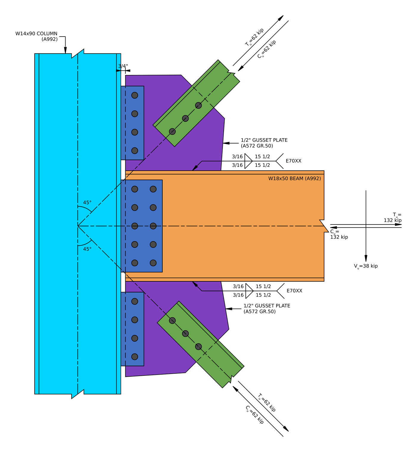
Örnek bağlantının yüksekliği. Both gussets are 15 1/2 in square, and each brace line runs through the work point where the beam and column centrelines meet.
Vertical brace connection design: bir bakışta adımlar
- Distribute the brace force with the Uniform Force Method.
- Destek cıvatalarındaki detay sınırlarını kontrol edin.
- Check the slip resistance of the brace bolts.
- Check bolt bearing and tear-out on the gusset.
- Check bolt bearing and tear-out on the brace angles.
- Check block shear of the gusset at the brace.
- Check block shear of the brace angles.
- Check the gusset in tension on its Whitmore section.
- Kayma gecikmeli gerilim kopmasında desteği kontrol edin.
- Check the gusset in compression buckling.
- Check the minimum fillet weld size at the beam.
- Check the gusset-to-beam weld.
- Check the gusset in shear yielding along the beam.
- Check the gusset in tension yielding along the beam.
- Check the beam web under the gusset.
- Check the detailing limits of the gusset-to-column single plate.
- Check the gusset-to-column bolt group.
- Check that the gusset single plate is thin enough to be ductile.
- Check bolt bearing on the gusset single plate.
- Check bolt bearing on the gusset at the column.
- Check block shear of the gusset single plate.
- Check block shear of the gusset at the column.
- Check the gusset single plate in shear.
- Check the gusset single plate in flexure.
- Check the gusset single plate in tension, with interaction.
- Check the gusset single plate in compression, with interaction.
- Check the weld size at the gusset single plate.
- Check the gusset single plate weld to the column.
- Check the column web under the gusset force.
- Check the detailing limits of the beam single plate.
- Check the beam-to-column bolt group.
- Check that the beam single plate is thin enough to be ductile.
- Check bolt bearing on the beam single plate.
- Check bolt bearing on the beam web.
- Check block shear of the beam single plate.
- Check block shear of the beam web under axial load.
- Check the beam single plate in shear.
- Check the beam single plate in flexure.
- Check the beam single plate in tension, with interaction.
- Check the beam single plate in compression, with interaction.
- Check the beam in tension rupture.
- Check the weld size at the beam single plate.
- Check the beam single plate weld to the column.
- Check the column web under the beam axial force.
Bu örnek için tasarım girdileri
Tasarım kodu AISC'dir 360-16 LRFD. Bölüm özellikleri AISC Kılavuzundan alınmıştır. The upper and lower brace connections are identical and mirror each other about the beam, and the report’s results for the two match exactly, yani Adımlar 2 -e 29 bir kez çalışılır ve her ikisine de uygulanır.
| Kalem | Sembol | Değer |
|---|---|---|
| Brace force, gerilim veya sıkıştırma (her destek) | [mathin] P [mathin] | 62 kip |
| Beam shear | [mathin] V_ Statistics script Complianz GDPR/CCPA 6 [mathin] | 38 kip |
| Beam transfer force, gerilim veya sıkıştırma | [mathin] T_ Statistics script Complianz GDPR/CCPA 5,\ C_ Statistics script Complianz GDPR/CCPA 4 [mathin] | 132 kip |
| Sütun | W14x90, A992 | |
| Sütun derinliği / ağ kalınlığı | [mathin] d_ Statistics script Complianz GDPR/CCPA 3,\ t_ Statistics script Complianz GDPR/CCPA 2 [mathin] | 14 içinde / 0.44 içinde |
| Sütun flanş genişliği / kalınlık | [mathin] b_ Statistics script Complianz GDPR/CCPA 1,\ t_ Statistics script Complianz GDPR/CCPA 0 [mathin] | 14.5 içinde / 0.71 içinde |
| Column kdes | [mathin] k_{des,c} [mathin] | 1.31 içinde |
| Işın | Ana farkın, kiriş flanşlarının destek kolonuna bağlantısında yattığını fark edebilirsiniz., A992 | |
| Işın derinliği / ağ kalınlığı | [mathin] d_{bm},\ t_{w,bm} [mathin] | 18 içinde / 0.355 içinde |
| Kiriş flanş genişliği / kalınlık | [mathin] b_{f,bm},\ t_{f,bm} [mathin] | 7.5 içinde / 0.57 içinde |
| Işın alanı / Neresi | [mathin] A_{bm},\ k_{des,bm} [mathin] | 14.7 inç² / 0.972 içinde |
| Beam setback from the column face | [mathin] clr [mathin] | 0.75 içinde |
| Column and beam yield / çekme gerilimi | [mathin] F_{y},\ F_{u} [mathin] | 50 ksi / 65 ksi |
| diş telleri (her biri) | 2L5x5x1/2, A36 | |
| Destek alanı (both angles) | [mathin] A_{br} [mathin] | 9.58 inç² |
| Angle leg thickness / merkez | [mathin] t_{l,br},\ \bar{y} [mathin] | 0.5 içinde / 1.42 içinde |
| Brace angle from the support | [mathin] \theta [mathin] | 45° |
| Brace unbraced length on the gusset | [mathin] L_{b} [mathin] | 9 içinde |
| Destek verimi / çekme gerilimi | [mathin] F_{y,br},\ F_{u,br} [mathin] | 36 ksi / 58 ksi |
| Esneklik modülü | [mathin] E [mathin] | 29000 ksi |
| Kalem | Sembol | Değer |
|---|---|---|
| Köşebent plakaları | 1/2 içinde, A572 Sınıfı 50, 15.5 x içinde 15.5 içinde | |
| Köşebent kalınlığı | [mathin] t_{gp} [mathin] | 0.5 içinde |
| Köşebent verimi / çekme gerilimi | [mathin] F_{y,gp},\ F_{u,gp} [mathin] | 50 ksi / 65 ksi |
| Cıvatalar (herşey) | 1 A490-SC'de, Class A surface | |
| Brace bolts: satırlar / aralık / çizgiler | [mathin] n_{r},\ s_{r},\ n_{c} [mathin] | 3 / 3 içinde / 1 |
| Brace bolts: gage on the angle leg / end distance | [mathin] g_{a},\ L_{ev} [mathin] | 3 içinde / 1.5 içinde |
| Destekteki delikler / köşebent | Standart (STD) / büyük boy (OV'ler) | |
| Gusset-to-beam weld | [mathin] W,\ F_{EXX} [mathin] | 3/16 in fillet both sides, E70XX, 15.5 in long |
| Gusset single plate | PL 3/8 x 3 3/4 x 12, A36 | |
| Gusset single plate bolts: satırlar / aralık / çizgiler | [mathin] n_{r},\ s_{r},\ n_{c} [mathin] | 4 / 3 içinde / 1 |
| Holes in gusset / gusset single plate | STD / horizontal short slots (HSSL) | |
| Gusset single plate weld to column | [mathin] W [mathin] | 1/4 in fillet both sides, E70XX |
| Beam single plate | PL 1/2 x 6 3/4 x 15, A572 Sınıfı 50 | |
| Beam single plate bolts: satırlar / aralık | [mathin] n_{r},\ s_{r} [mathin] | 5 / 3 içinde |
| Beam single plate bolts: çizgiler / aralık | [mathin] n_{c},\ s_{c} [mathin] | 2 / 3 içinde |
| Horizontal edge distance, all plates | [mathin] L_{eh} [mathin] | 1.5 içinde |
| Holes in beam web / beam single plate | STD / HSSL | |
| Beam single plate weld to column | [mathin] W [mathin] | 5/16 in fillet both sides, E70XX |
The A36 grade on the 3/8 in gusset single plate and the angles is normal for those parts. All three interfaces use slip-critical bolts, which is required here because every interface has oversized or slotted holes (AISC 360-16 J3.2).
Adım 1: Distribute the brace force with the Uniform Force Method (AISC Kılavuz Parçası 13)
The Uniform Force Method picks gusset dimensions so that the forces at the gusset-to-beam and gusset-to-column interfaces carry no moment, then splits the brace force between them. Whatever horizontal force the gusset puts into the column has to come back out of the beam, so it also changes the axial force in the beam-to-column connection.
Nerede [mathin] e_{b} = d_{bm}/2 = 9\,in [mathin], [mathin] e_{c} = d_{c}/2 = 7\,in [mathin], [mathin] \tan\theta = 1 [mathin] ve [mathin] \beta = 7.75\,in [mathin], half the gusset height on the column. The ideal centroid of the gusset-to-beam force follows from the UFM constraint:
[math] \alpha = e_{b} \tan\theta – e_{c} + \beta \tan\theta = (9\,in) \times (1) – (7\,in) + (7.75\,in) \times (1) = 9.75\,in [math]
The actual centroid of the gusset-to-beam weld is [mathin] \bar{\alpha} = 15.5/2 + 0.75 = 8.5\,in [mathin] from the column face: half the gusset length plus the setback. The distance that sets the force split is:
[math] r = \sqrt{\left( \alpha + e_{c} \right)^{2} + \left( \beta + e_{b} \right)^{2}} = \sqrt{\left( (9.75\,in) + (7\,in) \right)^{2} + \left( (7.75\,in) + (9\,in) \right)^{2}} = 23.688\,in [math]
The interface forces, ile [mathin] P = 62\,kip [mathin]:
[math] H_{c} = \frac{e_{c}\, P}{r} = \frac{(7\,in) \times (62\,kip)}{(23.688\,in)} = 18.321\,kip [math]
[math] H_{b} = \frac{\alpha\, P}{r} = \frac{(9.75\,in) \times (62\,kip)}{(23.688\,in)} = 25.519\,kip [math]
The vertical force at the beam would be [mathin] e_{b} P / r = 23.556\,kip [mathin]. This report uses Special Case 2 of the method (AISC Kılavuz Parçası 13, Tasarım Kılavuzu 29 Misal 5.3) and moves all of it to the gusset-to-column interface as [mathin] \Delta V_{b} = 23.556\,kip [mathin]. That way the beam-to-column connection does not have to carry the brace’s vertical force, at the cost of a moment on the gusset-to-beam interface:
[math] V_{c} = \frac{\beta\, P}{r} + \Delta V_{b} = \frac{(7.75\,in) \times (62\,kip)}{(23.688\,in)} + (23.556\,kip) = 43.841\,kip [math]
[math] V_{b} = \frac{e_{b}\, P}{r} – \Delta V_{b} = \frac{(9\,in) \times (62\,kip)}{(23.688\,in)} – (23.556\,kip) = 0\,kip [math]
[math] M_{b} = V_{b} \left| \alpha – \bar{\alpha} \right| + \Delta V_{b} \left| \alpha \right| = (0\,kip) \times \left| (9.75\,in) – (8.5\,in) \right| + (23.556\,kip) \times \left| (9.75\,in) \right| = 19.139\,kip{\cdot}ft [math]
The beam-to-column connection then carries the beam’s own forces plus the horizontal force each gusset sends straight to the column, which the beam has to bring back:
[math] C_{total} = T_{total} = C_{u} + \max\left( H_{c,upper},\, H_{c,lower} \right) = (132\,kip) + (18.321\,kip) = 150.32\,kip [math]
[math] V_{total} = V_{u} + V_{b,upper} + V_{b,lower} = (38\,kip) + (0\,kip) + (0\,kip) = 38\,kip [math]
Because the brace is at 45° and [mathin] e_{b} > e_{c} [mathin], the beam interface takes the larger share of the horizontal force, 25.519 kip 43.84 kip brace component.
Adım 2: Destek cıvatalarındaki limitlerin detaylandırılması (AISC 360-16 J3.3, J3.4, J3.5)
Cıvata düzeni oluşturulabilir olmalı ve mukavemet denklemlerinin ardındaki varsayımlarla eşleşmelidir.. Çok yakın cıvatalar delikler arasında yırtılır, ve çok yakın olan kenarlar yırtılır.
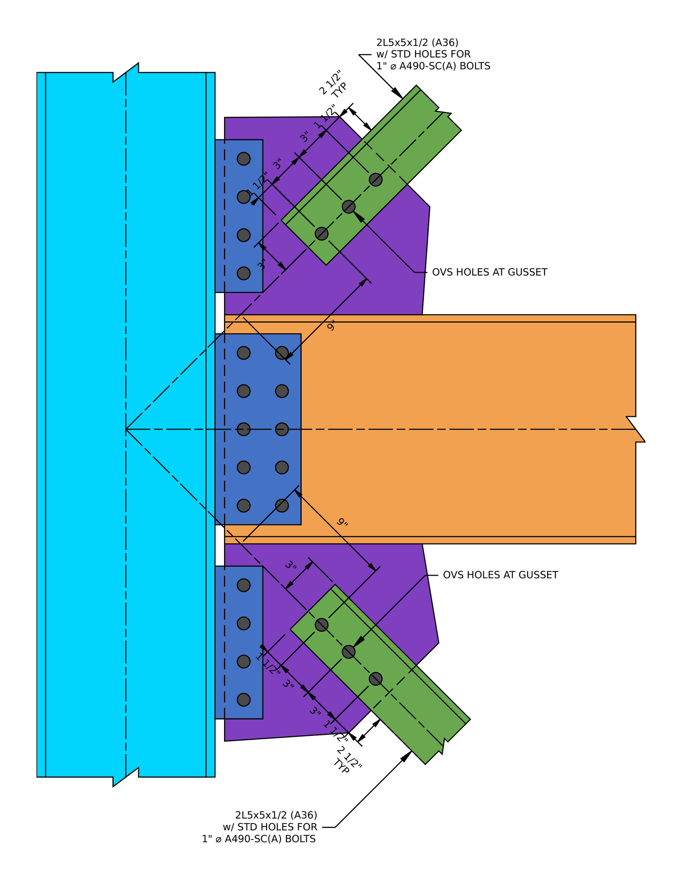
Destek bağlantı detayı. Three bolts per brace at 3 içinde, oversized holes in the gusset and standard holes in the angles.
için 1 cıvatada minimum aralık [mathin] 2\tfrac{2}{3} d_{b} = 2.667\,in [mathin] (J3.3) ve minimum kenar mesafesi 1.25 içinde (Tablo J3.4). Köşebent büyük boyutlu deliklere sahiptir, yani Tablo J3.5 artışı 1/8 minimum uç mesafesini yükseltir 1.375 içinde.
| Detaylandırma sınırı | Sınır (içinde) | Gerçek (içinde) | DCR | Sonuç |
|---|---|---|---|---|
| Minimum cıvata ölçüsü | 2.000 | 3.000 | 0.667 | GEÇMEK |
| Minimum cıvata sıra aralığı | 2.667 | 3.000 | 0.889 | GEÇMEK |
| Maksimum cıvata sırası aralığı | 6.000 | 3.000 | 0.500 | GEÇMEK |
| Gusset minimum vertical edge distance (OV'ler) | 1.375 | 1.500 | 0.917 | GEÇMEK |
| Minimum dikey kenar mesafesini destekleyin | 1.250 | 1.500 | 0.833 | GEÇMEK |
| Minimum yatay kenar mesafesini destekleyin | 1.250 | 2.000 | 0.625 | GEÇMEK |
The horizontal edge distance on the angle is the 5 in leg less the 3 ölçü olarak, 2 içinde. Yönetim sırası, büyük boyutlu delik artışıyla birlikte köşebent uç mesafesidir:
[math] DCR = \frac{d}{c} = \frac{(1.375)}{(1.5)} = 0.91667 [math]
DCR = 0.917 < 1.0, TAMAM MI
Adım 3: Slip resistance of the brace bolts (AISC 360-16 J3.8)
Köşebent büyük boyutlu deliklere sahiptir, hangi AISC 360-16 J3.2 allows only in slip-critical joints. The bolts are pretensioned, and friction between the angles and the gusset carries the brace force. Kontrol, eklemin faktörlü yük altında kaymamasıdır..
Nerede [mathin] \phi = 0.85 [mathin] büyük boyutlu delikler için, [mathin] \mu = 0.3 [mathin] for a Class A surface, [mathin] D_{u} = 1.13 [mathin], [mathin] h_{f} = 1 [mathin] çünkü dolgu maddesi yok, [mathin] T_{b} = 64\,kip [mathin] bir için 1 A490 cıvatasında (Tablo J3.1), [mathin] N_{s} = 2 [mathin] slip planes because the gusset sits between the two angles, [mathin] n_{r} = 3 [mathin] ve [mathin] n_{c} = 1 [mathin]:
[math] \phi R_{n} = \phi\, \mu\, D_{u}\, h_{f}\, T_{b}\, N_{s}\, n_{r}\, n_{c} [math]
[math] \phi R_{n} = (0.85) \times (0.3) \times (1.13) \times (1) \times (64\,kip) \times (2) \times (3) \times (1) [math]
[math] \phi R_{n} = 110.65\,kip [math]
DCR = 62 kip / 110.65 kip = 0.560 < 1.0, TAMAM MI
The double angle doubles the slip strength for free: each bolt clamps two faying surfaces.
Adım 4: Bolt bearing and tear-out on the gusset (AISC 360-16 J3.10)
Kayma açısından kritik cıvataların hala yatak açısından kontrol edilmesi gerekiyor, because if the joint slips the bolts bear on the sides of their holes. The bolt nearest the gusset’s edge has the least material in front of it.
Köşebent deliği büyük boyutlu, [mathin] d_{h} = 1.25\,in [mathin]. Clear distances for the end bolt and between bolts:
[math] l_{c1} = L_{ev} – \frac{d_{h}}{2} = (1.5\,in) – \frac{(1.25\,in)}{2} = 0.875\,in [math]
[math] l_{c2} = s_{r} – d_{h} = (3\,in) – (1.25\,in) = 1.75\,in [math]
Nerede [mathin] t_{gp} = 0.5\,in [mathin], [mathin] F_{u,gp} = 65\,ksi [mathin], [mathin] n_{r} = 3 [mathin], [mathin] n_{c} = 1 [mathin], [mathin] d_{b} = 1\,in [mathin] ve [mathin] \phi = 0.75 [mathin]:
[math] \phi R_{n} = \phi \left[ \min\left(1.2\, l_{c1},\, 2.4\, d_{b}\right) t_{gp} F_{u,gp}\, n_{c} + \min\left(1.2\, l_{c2},\, 2.4\, d_{b}\right) t_{gp} F_{u,gp}\, n_{c} \left( n_{r} – 1 \right) \right] [math]
[math] \phi R_{n} = (0.75) \times \left[ \min\left(1.2 \times (0.875\,in),\, 2.4 \times (1\,in)\right) \times (0.5\,in) \times (65\,ksi) \times (1) + \min\left(1.2 \times (1.75\,in),\, 2.4 \times (1\,in)\right) \times (0.5\,in) \times (65\,ksi) \times (1) \times ((3) – 1) \right] [math]
[math] \phi R_{n} = 127.97\,kip [math]
DCR = 62 kip / 127.97 kip = 0.484 < 1.0, TAMAM MI
Yırtma işlemi her cıvatayı yönetir, because the oversized hole cuts into the clear distance.
Adım 5: Destekte cıvata yatağı ve yırtılma (AISC 360-16 J3.10)
The same check applies to the angles. Both angle legs bear on the bolts, so the bearing thickness is twice the leg, [mathin] 2 t_{l,br} = 1\,in [mathin].
The angles have standard holes, [mathin] d_{h} = 1.125\,in [mathin]:
[math] l_{c1} = (1.5\,in) – \frac{(1.125\,in)}{2} = 0.9375\,in \qquad l_{c2} = (3\,in) – (1.125\,in) = 1.875\,in [math]
İle [mathin] F_{u,br} = 58\,ksi [mathin]:
[math] \phi R_{n} = \phi \left[ \min\left(1.2\, l_{c1},\, 2.4\, d_{b}\right) 2 t_{l,br} F_{u,br}\, n_{c} + \min\left(1.2\, l_{c2},\, 2.4\, d_{b}\right) 2 t_{l,br} F_{u,br}\, n_{c} \left( n_{r} – 1 \right) \right] [math]
[math] \phi R_{n} = (0.75) \times \left[ \min\left(1.2 \times (0.9375\,in),\, 2.4 \times (1\,in)\right) \times (1\,in) \times (58\,ksi) \times (1) + \min\left(1.2 \times (1.875\,in),\, 2.4 \times (1\,in)\right) \times (1\,in) \times (58\,ksi) \times (1) \times ((3) – 1) \right] [math]
[math] \phi R_{n} = 244.69\,kip [math]
DCR = 62 kip / 244.69 kip = 0.253 < 1.0, TAMAM MI
Adım 6: Block shear of the gusset at the brace (AISC 360-16 J4.3)
Köşebentin bir bloğu cıvataların etrafından yırtılabilir: shear along the bolt line and tension across to the gusset’s edge. With one bolt line, this is an L-shaped block.
Nerede [mathin] L_{eh,gp} = 2\,in [mathin] is the edge distance on the gusset beside the bolt line, [mathin] L_{br,gp} = 9\,in [mathin] is the length of brace on the gusset, ve her delik eklenir 1/16 in for damage (B4.3):
[math] A_{nt} = t_{gp} \left[ (n_{c}-1)\, s_{c} + L_{eh,gp} – (n_{c} – 0.5) \left( d_{h} + 0.0625\,in \right) \right] = (0.5\,in) \times \left[ 0 + (2\,in) – ((1) – 0.5) \times ((1.25\,in) + (0.0625\,in)) \right] = 0.67188\,in^{2} [math]
[math] A_{gv} = t_{gp} \left[ L_{ev} + (n_{r}-1)\, s_{r} \right] = (0.5\,in) \times \left[ (1.5\,in) + ((3)-1) \times (3\,in) \right] = 3.75\,in^{2} [math]
[math] A_{nv} = t_{gp} \left[ L_{br,gp} – L_{ev} – (n_{r} – 0.5)\left( d_{h} + 0.0625\,in \right) \right] = (0.5\,in) \times \left[ (9\,in) – (1.5\,in) – ((3) – 0.5) \times ((1.25\,in) + (0.0625\,in)) \right] = 2.1094\,in^{2} [math]
İle [mathin] U_{bs} = 1 [mathin] ve [mathin] \phi = 0.75 [mathin]:
[math] \phi R_{n} = \phi \left( 0.6\, F_{u} A_{nv} + U_{bs} F_{u} A_{nt} \le 0.6\, F_{y} A_{gv} + U_{bs} F_{u} A_{nt} \right) [math]
[math] \phi R_{n} = (0.75) \times \left( 0.6 \times (65\,ksi) \times (2.1094\,in^{2}) + (1) \times (65\,ksi) \times (0.67188\,in^{2}) \le 0.6 \times (50\,ksi) \times (3.75\,in^{2}) + (1) \times (65\,ksi) \times (0.67188\,in^{2}) \right) = 94.453\,kip [math]
DCR = 62 kip / 94.453 kip = 0.656 < 1.0, TAMAM MI
This is the highest strength check on the brace side. Shear rupture on the net section governs over shear yielding.
Adım 7: Desteğin blok kesmesi (AISC 360-16 J4.3)
The same tear-out can happen in the angle legs. Both angles act together, yani kalınlık [mathin] 2 t_{l,br} = 1\,in [mathin], with standard holes [mathin] d_{h} = 1.125\,in [mathin] ve 2 in leg edge [mathin] L_{eh,br} [mathin]:
[math] A_{nt} = (1\,in) \times \left[ 0 + (2\,in) – 0.5 \times ((1.125\,in) + (0.0625\,in)) \right] = 1.4063\,in^{2} [math]
[math] A_{gv} = (1\,in) \times \left[ (1.5\,in) + 2 \times (3\,in) \right] = 7.5\,in^{2} [math]
[math] A_{nv} = (1\,in) \times \left[ (9\,in) – (1.5\,in) – 2.5 \times ((1.125\,in) + (0.0625\,in)) \right] = 4.5313\,in^{2} [math]
[math] \phi R_{n} = (0.75) \times \left( 0.6 \times (58\,ksi) \times (4.5313\,in^{2}) + (1) \times (58\,ksi) \times (1.4063\,in^{2}) \le 0.6 \times (36\,ksi) \times (7.5\,in^{2}) + (1) \times (58\,ksi) \times (1.4063\,in^{2}) \right) = 179.44\,kip [math]
DCR = 62 kip / 179.44 kip = 0.346 < 1.0, TAMAM MI
Adım 8: Gusset in tension on the Whitmore section (AISC 360-16 J4.1)
The brace force spreads into the gusset at about 30° on each side of the bolt line. The Whitmore section is the width of that spread at the last bolt, and the gusset has to yield and rupture on it no earlier than the brace force.
İle [mathin] L_{br} = (n_{r}-1) s_{r} = 6\,in [mathin] ve [mathin] W_{br} = 0 [mathin] for a single bolt line (AISC Manual Fig. 9-1):
[math] W = 2\, L_{br} \tan 30^{\circ} + W_{br} = 2 \times (6\,in) \times \tan 30^{\circ} + 0 = 6.9282\,in [math]
[math] \phi R_{n,ty} = \phi\, F_{y,gp}\, t_{gp}\, W = (0.9) \times (50\,ksi) \times (0.5\,in) \times (6.9282\,in) = 155.88\,kip [math]
[math] \phi R_{n,tr} = \phi\, F_{u,gp}\, t_{gp} \left[ W – n_{c}\left( d_{h} + 0.0625\,in \right) \right] = (0.75) \times (65\,ksi) \times (0.5\,in) \times \left[ (6.9282\,in) – (1) \times ((1.25\,in) + (0.0625\,in)) \right] = 136.88\,kip [math]
DCR = 62 kip / 136.88 kip = 0.453 < 1.0, TAMAM MI
Adım 9: Kayma gecikmesi ile gerilim kopmasında destek (AISC 360-16 D3, J4.1)
Only one leg of each angle is bolted, so the stress in the outstanding legs has to lag in through the connected legs. The shear lag factor U reduces the net area to account for this.
İle [mathin] \bar{y} = 1.42\,in [mathin] and connection length [mathin] (n_{r}-1) s_{r} = 6\,in [mathin] (Tablo D3.1, Durum 2):
[math] U = 1 – \frac{\bar{y}}{(n_{r}-1)\, s_{r}} = 1 – \frac{(1.42\,in)}{((3)-1) \times (3\,in)} = 0.76343 [math]
[math] \phi R_{n} = \phi\, F_{u,br}\, U \left[ A_{br} – n_{c} \left( d_{h} + 0.0625\,in \right) 2 t_{l,br} \right] = (0.75) \times (58\,ksi) \times (0.76343) \times \left[ (9.58\,in^{2}) – (1) \times ((1.125\,in) + (0.0625\,in)) \times (1\,in) \right] = 278.71\,kip [math]
DCR = 62 kip / 278.71 kip = 0.222 < 1.0, TAMAM MI
Adım 10: Gusset in compression buckling (AISC 360-16 J4.4, E3)
When the brace pushes, the Whitmore strip of gusset between the last bolt and the gusset’s supported edges acts as a short column.
İle [mathin] K = 1.2 [mathin], [mathin] L = 9\,in [mathin] ve [mathin] r = t_{gp}/\sqrt{12} [mathin], [mathin] KL/r = 74.825 [mathin], which is above 25, so Chapter E applies. It is also below [mathin] 4.71\sqrt{E/F_{y}} = 113.43 [mathin], yani Denklem. E3-2 geçerlidir:
[math] F_{e} = \frac{\pi^{2} E}{\left( KL/r \right)^{2}} = \frac{\pi^{2} \times (29000\,ksi)}{(74.825)^{2}} = 51.122\,ksi [math]
[math] F_{cr} = 0.658^{\frac{F_{y}}{F_{e}}} F_{y} = 0.658^{\frac{(50\,ksi)}{(51.122\,ksi)}} \times (50\,ksi) = 33.204\,ksi [math]
[math] \phi R_{n} = \phi\, F_{cr}\, t_{gp}\, W = (0.9) \times (33.204\,ksi) \times (0.5\,in) \times (6.9282\,in) = 103.52\,kip [math]
DCR = 62 kip / 103.52 kip = 0.599 < 1.0, TAMAM MI
Buckling cuts the gusset’s compression strength to about two thirds of its yield strength in tension. Bir 9 in unbraced length is about the most a 1/2 in gusset can take at this load.
Adım 11: Minimum fillet weld size at the beam (AISC 360-16 J2.2b)
Birleştirdiği parçalara göre çok küçük olan köşe kaynağı soğudukça çatlayabilir. Table J2.4 sets the minimum by the thinner part, burada 1/2 köşebent içinde, yani minimum 3/16 içinde.
[math] DCR = \frac{d}{c} = \frac{(0.188)}{(0.188)} = 1 [math]
DCR = 1.000, TAMAM MI
bir oran 1.000 here means the 3/16 kaynakta tam olarak izin verilen en küçük boyuttur. Its strength is checked next.
Adım 12: Gusset-to-beam weld (AISC 360-16 J2.4, AISC Tasarım Kılavuzu 29)
The weld carries the horizontal force [mathin] H_{b} [mathin] along its length, plus the moment [mathin] M_{b} [mathin] Adımdan 1 as a varying normal force. The check uses the peak force per inch at the most loaded end.
Kaynak boyutunda ana metal sınırı (AISC Manuel Denklem. 9-2)
The weld cannot be stronger than the metal it is fused to. The gusset is welded on both faces, so it gets half its thickness per weld:
[math] D_{max} = \frac{t_{f,bm} F_{u,bm} \le 0.5\, t_{gp} F_{u,gp}}{3.09\,kip/in \times 1} = \frac{(0.57\,in) \times (65\,ksi) \le (0.25\,in) \times (65\,ksi)}{(3.09\,kip/in) \times (1)} = 5.2589 [math]
Etkili kaynak uzunluğu
[math] L_{w} = 2 \left[ L_{gp} – 2 W \right] = 2 \times \left[ (15.5\,in) – 2 \times (0.1875\,in) \right] = 30.25\,in [math]
Forces on the weld
The moment becomes a normal force using the plastic section of two weld lines, [mathin] L_{w}^{2}/8 [mathin]. İle [mathin] V_{b} = 0 [mathin]:
[math] V_{b,total} = \frac{8\, M_{b}}{L_{w}} + V_{b} = \frac{8 \times (19.139\,kip{\cdot}ft)}{(30.25\,in)} + (0\,kip) = 60.74\,kip [math]
[math] R = \sqrt{V_{b,total}^{2} + H_{b}^{2}} = \sqrt{(60.74\,kip)^{2} + (25.519\,kip)^{2}} = 65.883\,kip \qquad \theta = \tan^{-1}\left| \frac{60.74}{25.519} \right| = 67.211^{\circ} [math]
At the other end of the weld the normal force is [mathin] |V_{b} – 8 M_{b}/L_{w}| = 60.74\,kip [mathin], Bu yüzden [mathin] R_{min} = 65.883\,kip [mathin] too. AISC Kılavuz Parçası 13 applies a 1.25 weld ductility factor to the average of the two ends:
[math] R_{w} = \max\left( R,\, 1.25\, \frac{R + R_{min}}{2} \right) = \max\left( (65.883\,kip),\, 1.25 \times \frac{(65.883\,kip) + (65.883\,kip)}{2} \right) = 82.354\,kip [math]
Çünkü [mathin] V_{b} = 0 [mathin], the moment loads both ends equally (one in tension, one in compression), ve [mathin] R_{w} [mathin] is simply [mathin] 1.25 R [mathin].
Kaynak gücü (Eşitlik. J2-4)
[math] \phi R_{n} = \phi\, 0.6\, F_{EXX} \frac{\sqrt{2}}{2} \left( W \le \frac{D_{max}}{16} \right) \left[ 1 + 0.5 \left( \sin\theta \right)^{1.5} \right] L_{w} [math]
[math] \phi R_{n} = (0.75) \times 0.6 \times (70\,ksi) \times \frac{\sqrt{2}}{2} \times \left( (0.1875\,in) \le \frac{(5.2589)}{(16)} \right) \times \left[ 1 + 0.5 \times (\sin(67.211^{\circ}))^{1.5} \right] \times (30.25\,in) = 182.25\,kip [math]
DCR = 82.354 kip / 182.25 kip = 0.452 < 1.0, TAMAM MI
Nearly all of the weld force comes from the Special Case 2 an. Without it, the weld would only see the 25.519 kip horizontal force.
Adım 13: Gusset in shear yielding along the beam (AISC 360-16 J4.2)
Yatay kuvvet [mathin] H_{b} [mathin] shears the gusset along its welded edge. İle [mathin] A_{gv} = 15.5 \times 0.5 = 7.75\,in^{2} [mathin] ve [mathin] \phi = 1 [mathin] (Tasarım Kılavuzu 29 Misal 5.3):
[math] \phi R_{n} = \phi\, 0.6\, F_{y,gp} A_{gv} = (1) \times 0.6 \times (50\,ksi) \times (7.75\,in^{2}) = 232.5\,kip [math]
DCR = 25.519 kip / 232.5 kip = 0.110 < 1.0, TAMAM MI
Adım 14: Gusset in tension yielding along the beam (AISC 360-16 J4.1)
The moment puts one end of the gusset’s welded edge in tension. Following Design Guide 29 Misal 5.3, the normal force and the moment are added as stresses on the edge and turned back into an equivalent force over the full 15.5 uzunluğunda:
[math] N_{e} = \left| V_{b} \right| + \frac{4 \left| M_{b} \right|}{L_{gp}} = (0\,kip) + \frac{4 \times (19.139\,kip{\cdot}ft)}{(15.5\,in)} = 59.27\,kip [math]
[math] \phi R_{n} = \phi\, F_{y,gp}\, t_{gp}\, L_{gp} = (0.9) \times (50\,ksi) \times (0.5\,in) \times (15.5\,in) = 348.75\,kip [math]
DCR = 59.27 kip / 348.75 kip = 0.170 < 1.0, TAMAM MI
Adım 15: Beam web under the gusset (AISC 360-16 J10.3, J10.2)
The compression half of the gusset moment pushes on the beam flange next to the column, so the beam web there can cripple or yield locally. The gusset sits at the end of the beam, so the near-end forms of the equations apply.
The report applies half the peak normal force, [mathin] 60.74/2 = 30.37\,kip [mathin], over half the gusset length, [mathin] l_{b} = 7.75\,in [mathin]. That models the compression side of the moment couple. İle [mathin] \phi = 0.75 [mathin], [mathin] l_{b}/d = 0.43 > 0.2 [mathin] ve [mathin] Q_{f} = 1 [mathin]:
[math] \phi R_{n,wlc} = \phi\, 0.4\, t_{w}^{2} \left[ 1 + \left( \frac{4 l_{b}}{d} – 0.2 \right) \left( \frac{t_{w}}{t_{f}} \right)^{1.5} \right] \sqrt{\frac{E\, F_{y}\, t_{f}}{t_{w}}}\, Q_{f} [math]
[math] \phi R_{n,wlc} = (0.75) \times 0.4 \times (0.355\,in)^{2} \times \left[ 1 + \left( \frac{4 \times (7.75\,in)}{(18\,in)} – 0.2 \right) \times \left( \frac{(0.355\,in)}{(0.57\,in)} \right)^{1.5} \right] \times \sqrt{\frac{(29000\,ksi) \times (50\,ksi) \times (0.57\,in)}{(0.355\,in)}} \times (1) = 100.85\,kip [math]
Web local yielding near the member end (Eşitlik. J10-3), ile [mathin] \phi = 1 [mathin]:
[math] \phi R_{n,wly} = \phi\, F_{y}\, t_{w} \left( 2.5\, k_{des} + l_{b} \right) = (1) \times (50\,ksi) \times (0.355\,in) \times \left( 2.5 \times (0.972\,in) + (7.75\,in) \right) = 180.69\,kip [math]
DCR = 30.37 kip / 100.85 kip = 0.301 < 1.0, TAMAM MI
The report labels the crippling equation J10-4, but the numbers it substitutes are the near-end form with 0.4 ve (4lb/d − 0.2), which is Eq. J10-5b. That is the right form for a force this close to the beam end.
Adım 16: Detailing limits of the gusset single plate (AISC 360-16 J3.3, J3.4, J3.5)
The gusset bolts to a 3/8 in plate welded to the column flange. Plakanın yatay kısa yuvaları vardır, which add 1/8 in to the minimum edge distance across the slot (Tablo J3.5).
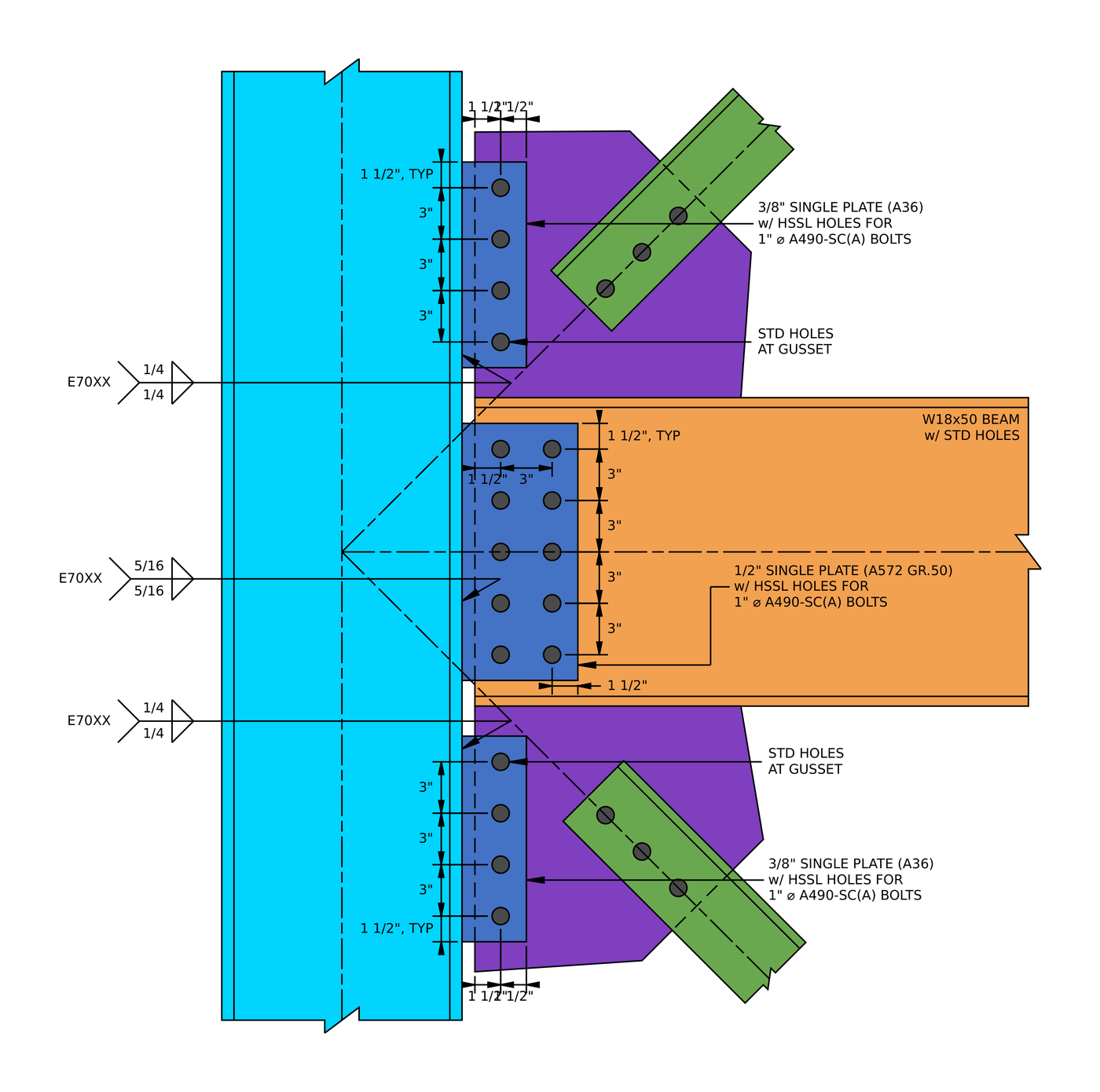
Single plate detail. The gusset plates take four bolts in one line, and the beam plate takes two lines of five. All three plates have horizontal short slots.
| Detaylandırma sınırı | Sınır (içinde) | Gerçek (içinde) | DCR | Sonuç |
|---|---|---|---|---|
| Minimum cıvata sıra aralığı | 2.667 | 3.000 | 0.889 | GEÇMEK |
| Maksimum cıvata sırası aralığı | 6.000 | 3.000 | 0.500 | GEÇMEK |
| Plaka minimum dikey kenar mesafesi | 1.250 | 1.500 | 0.833 | GEÇMEK |
| Plaka minimum yatay kenar mesafesi (HSSL) | 1.375 | 1.500 | 0.917 | GEÇMEK |
| Gusset minimum horizontal edge distance | 1.250 | 1.500 | 0.833 | GEÇMEK |
| Minimum plate depth | 7.750 | 12.000 | 0.646 | GEÇMEK |
The minimum plate depth is half the 15.5 in gusset edge on the column, so the plate supports at least half the gusset.
DCR = 1.375 / 1.5 = 0.917 < 1.0, TAMAM MI
Adım 17: Gusset-to-column bolt group (AISC 360-16 J3.8, AISC Kılavuz Parçası 7)
The four bolts carry [mathin] V_{c} [mathin] ve [mathin] H_{c} [mathin] birlikte, at an eccentricity from the weld line. The instantaneous center of rotation method gives the coefficient C: the number of bolts the eccentric group is worth.
The resultant and its angle from vertical:
[math] R = \sqrt{V_{c}^{2} + H_{c}^{2}} = \sqrt{(43.841\,kip)^{2} + (18.321\,kip)^{2}} = 47.515\,kip \qquad \theta = \tan^{-1}\left( \frac{18.321}{43.841} \right) = 22.681^{\circ} [math]
The eccentricity is the distance from the weld to the bolt line, [mathin] e = 2.25\,in [mathin]. For bolts at (0, 0), (0, 3), (0, 6) ve (0, 9), the iteration puts the instantaneous center at [mathin] x_{ic} = -4.0517\,in [mathin], [mathin] y_{ic} = 6.7655\,in [mathin], hangi verir [mathin] C = 3.14 [mathin] and the moment coefficient [mathin] C’ = 11.256\,in [mathin]. Each bolt is slip-critical, ile [mathin] N_{s} = 1 [mathin]:
[math] \phi R_{n} = \phi\, \mu\, D_{u}\, h_{f}\, T_{b}\, N_{s}\, C = (0.85) \times (0.3) \times (1.13) \times (1) \times (64\,kip) \times (1) \times (3.14) = 57.907\,kip [math]
DCR = 47.515 kip / 57.907 kip = 0.821 < 1.0, TAMAM MI
The slots are horizontal and the resultant leans 22.7° toward them, so the report keeps φ = 0.85 for slotted holes. Bolt slip is the highest check on the gusset side.
Adım 18: Ductility of the gusset single plate (AISC Kılavuz Parçası 10)
A single plate has to yield in flexure before the bolts shear off, so the plate cannot be too thick. AISC Kılavuz Parçası 10 (Eşitlik. 10-3 ve 10-4) gives the maximum thickness from the moment the bolt group can carry.
İle [mathin] F_{nv} = 68\,ksi [mathin], [mathin] d_{b} = 1\,in [mathin], [mathin] C’ = 11.256\,in [mathin], [mathin] F_{y} = 36\,ksi [mathin] ve [mathin] h = 12\,in [mathin]:
[math] M_{max} = \frac{F_{nv}}{0.90} \frac{\pi d_{b}^{2}}{4} C’ = \frac{(68\,ksi)}{0.90} \times \frac{\pi \times (1\,in)^{2}}{4} \times (11.256\,in) = 55.664\,kip{\cdot}ft [math]
[math] t_{max} = \frac{6\, M_{max}}{F_{y}\, h^{2}} = \frac{6 \times (55.664\,kip{\cdot}ft)}{(36\,ksi) \times (12\,in)^{2}} = 0.77311\,in [math]
DCR = 0.375 içinde / 0.77311 içinde = 0.485 < 1.0, TAMAM MI
Adım 19: Bolt bearing on the gusset single plate (AISC 360-16 J3.10)
The plate is checked for bearing and tear-out in each direction of load separately, then for both together. Each strength is the average per bolt multiplied by C, so it matches the bolt group’s capacity.
Dikey (makaslama) yön
The vertical hole size is the standard 1.125 içinde, Bu yüzden [mathin] l_{c1} = 0.9375\,in [mathin] ve [mathin] l_{c2} = 1.875\,in [mathin]. İle [mathin] t = 0.375\,in [mathin], [mathin] F_{u} = 58\,ksi [mathin] ve [mathin] n_{r} = 4 [mathin]:
[math] \phi R_{n,v} = \phi \left[ \min\left(1.2\, l_{c1},\, 2.4\, d_{b}\right) t F_{u} + \min\left(1.2\, l_{c2},\, 2.4\, d_{b}\right) t F_{u} \left( n_{r} – 1 \right) \right] \frac{C}{n_{r}} [math]
[math] \phi R_{n,v} = (0.75) \times \left[ \min\left(1.125,\, 2.4\right) \times (0.375\,in) \times (58\,ksi) + \min\left(2.25,\, 2.4\right) \times (0.375\,in) \times (58\,ksi) \times ((4) – 1) \right] \times \frac{(3.14)}{(4)} = 100.84\,kip [math]
DCR = 43.841 kip / 100.84 kip = 0.435 < 1.0, TAMAM MI
Yatay (eksenel) yön
Across the slot the hole is 1.3125 in long, Bu yüzden [mathin] l_{c1} = 1.5 – 1.3125/2 = 0.84375\,in [mathin]. There is one bolt line, so the inner-bolt term is multiplied by [mathin] (n_{c} – 1) = 0 [mathin] and its negative [mathin] l_{c2} = -1.3125\,in [mathin] has no effect:
[math] \phi R_{n,a} = \phi \left[ \min\left(1.2\, l_{c1},\, 2.4\, d_{b}\right) t F_{u} + \min\left(1.2\, l_{c2},\, 2.4\, d_{b}\right) t F_{u} \left( n_{c} – 1 \right) \right] \frac{C}{n_{c}} [math]
[math] \phi R_{n,a} = (0.75) \times \left[ \min\left(1.0125,\, 2.4\right) \times (0.375\,in) \times (58\,ksi) + 0 \right] \times \frac{(3.14)}{(1)} = 51.862\,kip [math]
DCR = 18.321 kip / 51.862 kip = 0.353 < 1.0, TAMAM MI
Etkileşim
[math] \left( \frac{V_{c}}{\phi R_{n,v}} \right)^{2} + \left( \frac{H_{c}}{\phi R_{n,a}} \right)^{2} = \left( \frac{(43.841\,kip)}{(100.84\,kip)} \right)^{2} + \left( \frac{(18.321\,kip)}{(51.862\,kip)} \right)^{2} = 0.31381 [math]
DCR = 0.314 < 1.0, TAMAM MI
Adım 20: Bolt bearing on the gusset at the column (AISC 360-16 J3.10)
The same three checks apply to the 1/2 köşebent içinde, standart delikleri olan.
Dikey (makaslama) yön
NS 12 in plate is centred on the 15.5 in gusset edge, so the gusset’s end distance is [mathin] L_{ev} = (15.5 – 12)/2 + 1.5 = 3.25\,in [mathin] ve [mathin] l_{c1} = 2.6875\,in [mathin]. İle [mathin] t = 0.5\,in [mathin] ve [mathin] F_{u} = 65\,ksi [mathin]:
[math] \phi R_{n,v} = (0.75) \times \left[ \min\left(3.225,\, 2.4\right) \times (0.5\,in) \times (65\,ksi) + \min\left(2.25,\, 2.4\right) \times (0.5\,in) \times (65\,ksi) \times ((4) – 1) \right] \times \frac{(3.14)}{(4)} = 175.08\,kip [math]
DCR = 43.841 kip / 175.08 kip = 0.250 < 1.0, TAMAM MI
Yatay (eksenel) yön
İle 1.5 in edge and the standard hole, [mathin] l_{c1} = 0.9375\,in [mathin]:
[math] \phi R_{n,a} = (0.75) \times \left[ \min\left(1.125,\, 2.4\right) \times (0.5\,in) \times (65\,ksi) + 0 \right] \times \frac{(3.14)}{(1)} = 86.105\,kip [math]
DCR = 18.321 kip / 86.105 kip = 0.213 < 1.0, TAMAM MI
Etkileşim
[math] \left( \frac{(43.841\,kip)}{(175.08\,kip)} \right)^{2} + \left( \frac{(18.321\,kip)}{(86.105\,kip)} \right)^{2} = 0.10798 [math]
DCR = 0.108 < 1.0, TAMAM MI
Adım 21: Block shear of the gusset single plate (AISC 360-16 J4.3)
A block can tear out of the plate under the vertical force, under the horizontal force, veya her ikisinin altında. The vertical case is an L-shaped block down the bolt line. The horizontal case has two shapes, L and U, and the weaker governs.
Dikey (makaslama) yön
The tension leg crosses half a slotted hole, [mathin] d_{h} = 1.3125\,in [mathin]:
[math] A_{nt} = (0.375\,in) \times \left[ (1.5\,in) – 0.5 \times ((1.3125\,in) + (0.0625\,in)) \right] = 0.30469\,in^{2} [math]
[math] A_{gv} = (0.375\,in) \times \left[ (1.5\,in) + 3 \times (3\,in) \right] = 3.9375\,in^{2} [math]
[math] A_{nv} = t \left[ h_{sp} – L_{ev} – (n_{r} – 0.5)\left( d_{h} + 0.0625\,in \right) \right] = (0.375\,in) \times \left[ (12\,in) – (1.5\,in) – 3.5 \times ((1.125\,in) + (0.0625\,in)) \right] = 2.3789\,in^{2} [math]
[math] \phi R_{n} = (0.75) \times \left( 0.6 \times (58\,ksi) \times (2.3789\,in^{2}) + (1) \times (58\,ksi) \times (0.30469\,in^{2}) \le 0.6 \times (36\,ksi) \times (3.9375\,in^{2}) + (1) \times (58\,ksi) \times (0.30469\,in^{2}) \right) = 75.343\,kip [math]
DCR = 43.841 kip / 75.343 kip = 0.582 < 1.0, TAMAM MI
Yatay (eksenel) yön
The L pattern tears in tension along the bolt line and shears across the top. The shear leg runs from the bolt to the unbraced end of the plate, [mathin] b_{sp} – L_{b,sp} = 3.75 – 2.25 = 1.5\,in [mathin]:
[math] A_{nt} = (0.375\,in) \times \left[ 3 \times (3\,in) + (1.5\,in) – 3.5 \times (1.1875\,in) \right] = 2.3789\,in^{2} \quad A_{gv} = 0.5625\,in^{2} \quad A_{nv} = 0.30469\,in^{2} [math]
[math] \phi R_{n,L} = (0.75) \times \left( 0.6 \times (58\,ksi) \times (0.30469\,in^{2}) + (1) \times (58\,ksi) \times (2.3789\,in^{2}) \le 0.6 \times (36\,ksi) \times (0.5625\,in^{2}) + (1) \times (58\,ksi) \times (2.3789\,in^{2}) \right) = 111.43\,kip [math]
The U pattern tears in tension between the outer bolts and shears out at the top and bottom:
[math] A_{nt} = (0.375\,in) \times \left[ 3 \times (3\,in) – 3 \times (1.1875\,in) \right] = 2.0391\,in^{2} \quad A_{gv} = 2 \times (0.375\,in) \times (1.5\,in) = 1.125\,in^{2} \quad A_{nv} = 0.60938\,in^{2} [math]
[math] \phi R_{n,U} = (0.75) \times \left( 0.6 \times (58\,ksi) \times (0.60938\,in^{2}) + (1) \times (58\,ksi) \times (2.0391\,in^{2}) \le 0.6 \times (36\,ksi) \times (1.125\,in^{2}) + (1) \times (58\,ksi) \times (2.0391\,in^{2}) \right) = 104.6\,kip [math]
DCR = 18.321 kip / 104.6 kip = 0.175 < 1.0, TAMAM MI
Etkileşim
[math] \left( \frac{(43.841\,kip)}{(75.343\,kip)} \right)^{2} + \left( \frac{(18.321\,kip)}{(104.6\,kip)} \right)^{2} = 0.36926 [math]
DCR = 0.369 < 1.0, TAMAM MI
Adım 22: Block shear of the gusset at the column (AISC 360-16 J4.3)
The same patterns apply to the gusset, with its 3.25 in end distance.
Dikey (makaslama) yön
[math] A_{nt} = (0.5\,in) \times \left[ (1.5\,in) – 0.5 \times ((1.3125\,in) + (0.0625\,in)) \right] = 0.40625\,in^{2} [math]
[math] A_{gv} = (0.5\,in) \times \left[ (3.25\,in) + 3 \times (3\,in) \right] = 6.125\,in^{2} \qquad A_{nv} = (0.5\,in) \times \left[ (15.5\,in) – (3.25\,in) – 3.5 \times (1.1875\,in) \right] = 4.0469\,in^{2} [math]
[math] \phi R_{n} = (0.75) \times \left( 0.6 \times (65\,ksi) \times (4.0469\,in^{2}) + (1) \times (65\,ksi) \times (0.40625\,in^{2}) \le 0.6 \times (50\,ksi) \times (6.125\,in^{2}) + (1) \times (65\,ksi) \times (0.40625\,in^{2}) \right) = 138.18\,kip [math]
DCR = 43.841 kip / 138.18 kip = 0.317 < 1.0, TAMAM MI
The tension area uses the plate’s 1.3125 in slot length rather than the gusset’s 1.125 in standard hole. That removes a little more area than the gusset actually loses, so the result is slightly conservative.
Yatay (eksenel) yön
[math] L:\ A_{nt} = 4.0469\,in^{2},\ A_{gv} = 0.75\,in^{2},\ A_{nv} = 0.40625\,in^{2} \Rightarrow \phi R_{n,L} = 209.17\,kip [math]
[math] U:\ A_{nt} = (0.5\,in) \times \left[ 9\,in – 3 \times (1.1875\,in) \right] = 2.7188\,in^{2},\ A_{gv} = 1.5\,in^{2},\ A_{nv} = 0.8125\,in^{2} \Rightarrow \phi R_{n,U} = 156.3\,kip [math]
DCR = 18.321 kip / 156.3 kip = 0.117 < 1.0, TAMAM MI
Etkileşim
[math] \left( \frac{(43.841\,kip)}{(138.18\,kip)} \right)^{2} + \left( \frac{(18.321\,kip)}{(156.3\,kip)} \right)^{2} = 0.11441 [math]
DCR = 0.114 < 1.0, TAMAM MI
Adım 23: Gusset single plate in shear (AISC 360-16 J4.2)
The plate carries [mathin] V_{c} [mathin] as shear over its 12 in depth. It is checked for yielding on the gross section and rupture through the bolt holes.
[math] \phi R_{n,sy} = \phi\, 0.6\, F_{y} A_{gv} = (1) \times 0.6 \times (36\,ksi) \times (4.5\,in^{2}) = 97.2\,kip [math]
[math] A_{nv} = t \left[ h_{sp} – n_{r} \left( d_{h} + 0.0625\,in \right) \right] = (0.375\,in) \times \left[ (12\,in) – (4) \times (1.1875\,in) \right] = 2.7188\,in^{2} [math]
[math] \phi R_{n,sr} = \phi\, 0.6\, F_{u} A_{nv} = (0.75) \times 0.6 \times (58\,ksi) \times (2.7188\,in^{2}) = 70.959\,kip [math]
DCR = 43.841 kip / 70.959 kip = 0.618 < 1.0, TAMAM MI
Adım 24: Gusset single plate in flexure (AISC Kılavuz Parçası 9, AISC 360-16 F11)
The vertical force acts at the bolt line, 2.25 kaynaktan içeri, so the plate bends. The report treats the plate like a double coped beam: a rectangular section that can buckle laterally over its unbraced length [mathin] L_{b,sp} = 2.25\,in [mathin].
The slenderness ratio [mathin] L_{b} d / t^{2} = 2.25 \times 12 / 0.375^{2} = 192 [mathin] falls between [mathin] 0.08E/F_{y} = 64.444 [mathin] ve [mathin] 1.9E/F_{y} = 1530.6 [mathin], yani Denklem. F11-2 geçerlidir. İle [mathin] Z = 13.5\,in^{3} [mathin], [mathin] S = 9\,in^{3} [mathin] and the cope depth taken as zero (AISC Manuel Denklem. 9-15):
[math] C_{b} = \left[ 3 + \ln\left( \frac{L_{b,sp}}{h_{sp}} \right) \right] \left( 1 – \frac{d_{c,sp}}{h_{sp}} \right) \ge 1.84 = \left[ 3 + \ln\left( \frac{(2.25\,in)}{(12\,in)} \right) \right] \times (1 – 0) \ge 1.84 = 1.84 [math]
[math] \phi M_{n} = \phi \left[ C_{b} \left[ 1.52 – 0.274 \left( \frac{L_{b} d}{t^{2}} \right) \left( \frac{F_{y}}{E} \right) \right] F_{y} S \le F_{y} Z \right] = (0.9) \times \left[ (1.84) \times \left[ 1.52 – 0.274 \times (192) \times \frac{(36\,ksi)}{(29000\,ksi)} \right] \times (36\,ksi) \times (9\,in^{3}) \le (36\,ksi) \times (13.5\,in^{3}) \right] = 36.45\,kip{\cdot}ft [math]
[math] \phi V_{n,y} = \frac{\phi M_{n}}{L_{b,sp}} = \frac{(36.45\,kip{\cdot}ft)}{(2.25\,in)} = 194.4\,kip [math]
Flexural rupture uses the net plastic modulus through the holes (AISC Manuel Tablosu 15-3):
[math] Z_{net} = \frac{t\, h^{2}}{4} – t \left( d_{h} + 0.0625\,in \right) s_{r} \left\lfloor \frac{n_{r}^{2}}{4} \right\rfloor – \left[ n_{r}\ \text{odd} \right] \frac{t \left( d_{h} + 0.0625\,in \right)^{2}}{4} = 8.1563\,in^{3} [math]
[math] \phi M_{n} = \phi\, F_{u}\, Z_{net} = (0.75) \times (58\,ksi) \times (8.1563\,in^{3}) = 29.566\,kip{\cdot}ft \qquad \phi V_{n,r} = \frac{(29.566\,kip{\cdot}ft)}{(2.25\,in)} = 157.69\,kip [math]
DCR = 43.841 kip / 157.69 kip = 0.278 < 1.0, TAMAM MI
The plate is short and deep, so lateral-torsional buckling does not reduce it. The F11-2 value is capped at the plastic moment [mathin] F_{y} Z [mathin].
Adım 25: Gusset single plate in tension, with interaction (AISC 360-16 J4.1, H1)
When the brace pulls, [mathin] H_{c} [mathin] puts the plate in tension.
[math] \phi R_{n,ty} = (0.9) \times (36\,ksi) \times (0.375\,in) \times (12\,in) = 145.8\,kip [math]
[math] \phi R_{n,tr} = (0.75) \times (58\,ksi) \times (0.375\,in) \times \left[ (12\,in) – (4) \times (1.1875\,in) \right] = 118.27\,kip [math]
DCR = 18.321 kip / 118.27 kip = 0.155 < 1.0, TAMAM MI
The plate carries tension, bending and shear at the same time. Since the axial ratio is below 0.2, the report uses the AISC H1-1b form for axial plus flexure, then adds the squared shear ratio:
[math] \left( \frac{H_{c}}{2\, \phi R_{n}} + \frac{V_{c}}{\phi V_{n}} \right)^{2} + \left( \frac{V_{c}}{\phi R_{n,v}} \right)^{2} = \left( \frac{(18.321\,kip)}{2 \times (118.27\,kip)} + \frac{(43.841\,kip)}{(194.4\,kip)} \right)^{2} + \left( \frac{(43.841\,kip)}{(70.959\,kip)} \right)^{2} = 0.47351 [math]
DCR = 0.474 < 1.0, TAMAM MI
The flexure term uses the 194.4 kip from flexural yielding, not the 157.69 kip from rupture that governed Step 24.
Adım 26: Gusset single plate in compression, with interaction (AISC 360-16 J4.4, H1)
When the brace pushes, the plate is in compression. İle [mathin] K = 1.2 [mathin] ve [mathin] L = 2.25\,in [mathin], [mathin] KL/r = 24.942 \le 25 [mathin], so it does not buckle and Eq. J4-6 geçerlidir:
[math] \phi R_{n} = \phi\, F_{y}\, t\, h_{sp} = (0.9) \times (36\,ksi) \times (0.375\,in) \times (12\,in) = 145.8\,kip [math]
DCR = 18.321 kip / 145.8 kip = 0.126 < 1.0, TAMAM MI
[math] \left( \frac{(18.321\,kip)}{2 \times (145.8\,kip)} + \frac{(43.841\,kip)}{(194.4\,kip)} \right)^{2} + \left( \frac{(43.841\,kip)}{(70.959\,kip)} \right)^{2} = 0.46486 [math]
DCR = 0.465 < 1.0, TAMAM MI
Adım 27: Weld size at the gusset single plate (AISC Kılavuz Parçası 10)
Two checks on weld size. The weld has to fit in the 0.75 in setback, and it has to be strong enough to develop the plate, so that the plate yields before the weld breaks. AISC Kılavuzu sayfası 10-87 sets the second at 5/8 plaka kalınlığı:
[math] DCR_{clr} = \frac{(0.25)}{(0.75)} = 0.333 \qquad W_{duc} = \frac{5}{8}\, t_{sp} = \frac{5}{8} \times (0.375\,in) = 0.23438\,in [math]
DCR = 0.23438 içinde / 0.25 içinde = 0.938 < 1.0, TAMAM MI
Adım 28: Gusset single plate weld to the column (AISC 360-16 J2.4)
The plate is welded to the column flange on both faces. The weld carries the same resultant as the bolts, 47.515 kip at 22.681° from its axis.
[math] D_{max} = \frac{\frac{t_{sp}}{2} F_{u,sp} \le t_{f,c} F_{u,c}}{3.09\,kip/in} = \frac{(0.1875\,in) \times (58\,ksi) \le (0.71\,in) \times (65\,ksi)}{(3.09\,kip/in) \times (1)} = 3.5194 [math]
[math] L_{w} = 2 \left[ h_{sp} – 2W \right] = 2 \times \left[ (12\,in) – 2 \times (0.25\,in) \right] = 23\,in [math]
[math] \phi R_{n} = (0.75) \times 0.6 \times (70\,ksi) \times \frac{\sqrt{2}}{2} \times \left( (0.25\,in) \le \frac{(3.5194)}{(16)} \right) \times \left[ 1 + 0.5 \times (\sin(22.681^{\circ}))^{1.5} \right] \times (23\,in) = 126.18\,kip [math]
DCR = 47.515 kip / 126.18 kip = 0.377 < 1.0, TAMAM MI
NS 3/8 in A36 plate limits the weld here: [mathin] 3.5194/16 = 0.22\,in [mathin], sadece bu yüzden 0.22 in of the 1/4 kaynak sayımlarında. A bigger weld would add nothing without a thicker plate.
Adım 29: Column web under the gusset force (AISC 360-16 J10.3, J10.2)
[mathin] H_{c} [mathin] pushes or pulls on the column flange over the 12 tabakta. İle [mathin] l_{b} = 12\,in [mathin]:
[math] \phi R_{n,wlc} = (0.75) \times 0.8 \times (0.44\,in)^{2} \times \left[ 1 + 3 \times \left( \frac{(12\,in)}{(14\,in)} \right) \times \left( \frac{(0.44\,in)}{(0.71\,in)} \right)^{1.5} \right] \times \sqrt{\frac{(29000\,ksi) \times (50\,ksi) \times (0.71\,in)}{(0.44\,in)}} \times (1) = 400.58\,kip [math]
[math] \phi R_{n,wly} = (1) \times (50\,ksi) \times (0.44\,in) \times \left( 5 \times (1.31\,in) + (12\,in) \right) = 408.1\,kip [math]
DCR = 18.321 kip / 400.58 kip = 0.046 < 1.0, TAMAM MI
Adım 30: Detailing limits of the beam single plate (AISC 360-16 J3.3, J3.4, J3.5)
The beam connection is a 1/2 in single plate with two bolt lines of five, welded to the column flange. Plakanın yatay kısa yuvaları vardır, and the beam web has standard holes. Its layout is in the single plate detail under Step 16.
| Detaylandırma sınırı | Sınır (içinde) | Gerçek (içinde) | DCR | Sonuç |
|---|---|---|---|---|
| Minimum cıvata sıra aralığı | 2.667 | 3.000 | 0.889 | GEÇMEK |
| Maksimum cıvata sırası aralığı | 6.000 | 3.000 | 0.500 | GEÇMEK |
| Minimum cıvata sütun aralığı | 2.667 | 3.000 | 0.889 | GEÇMEK |
| Maksimum cıvata sütun aralığı | 6.000 | 3.000 | 0.500 | GEÇMEK |
| Plaka minimum dikey kenar mesafesi | 1.250 | 1.500 | 0.833 | GEÇMEK |
| Plaka minimum yatay kenar mesafesi (HSSL) | 1.375 | 1.500 | 0.917 | GEÇMEK |
| Beam web minimum horizontal edge distance | 1.250 | 1.500 | 0.833 | GEÇMEK |
| Minimum plate depth | 7.750 | 15.000 | 0.517 | GEÇMEK |
| Maximum plate depth | 16.000 | 15.000 | 0.938 | GEÇMEK |
The plate depth limits keep the plate between the beam fillets. The maximum is about the beam depth less [mathin] 2 k_{des} [mathin], and the minimum is half the web’s T dimension (AISC Kılavuz Parçası 10).
DCR = 15 / 16 = 0.938 < 1.0, TAMAM MI
Adım 31: Beam-to-column bolt group (AISC 360-16 J3.8, AISC Kılavuz Parçası 7)
The ten bolts carry the beam shear and the 150.32 kip axial force together, at an eccentricity from the weld. This is the most heavily loaded part of the connection.
[math] R = \sqrt{V_{total}^{2} + T_{total}^{2}} = \sqrt{(38\,kip)^{2} + (150.32\,kip)^{2}} = 155.05\,kip \qquad \theta = \tan^{-1}\left( \frac{150.32}{38} \right) = 75.813^{\circ} [math]
The eccentricity is [mathin] e = 3.75\,in [mathin], from the weld to the centroid of the two bolt lines. With bolts at x = 0 ve 3 in and y = 0, 3, 6, 9 ve 12 içinde, the instantaneous center is at [mathin] x_{ic} = -0.42058\,in [mathin], [mathin] y_{ic} = 14.882\,in [mathin], verme [mathin] C = 8.63 [mathin] ve [mathin] C’ = 38.669\,in [mathin]:
[math] \phi R_{n} = \phi\, \mu\, D_{u}\, h_{f}\, T_{b}\, N_{s}\, C = (0.85) \times (0.3) \times (1.13) \times (1) \times (64\,kip) \times (1) \times (8.63) = 159.15\,kip [math]
DCR = 155.05 kip / 159.15 kip = 0.974 < 1.0, TAMAM MI
Bu, tüm bağlantının yönetim kontrolüdür. The load is mostly axial, at 75.8° from vertical, so it runs along the horizontal slots, and that is why φ = 0.85 applies here. The resultant is far from the bolt group’s centroid line, but because it is nearly axial the eccentricity costs little: C = 8.63 out of 10 cıvatalar.
Adım 32: Ductility of the beam single plate (AISC Kılavuz Parçası 10)
İle [mathin] C’ = 38.669\,in [mathin], [mathin] F_{y} = 50\,ksi [mathin] ve [mathin] h = 15\,in [mathin]:
[math] M_{max} = \frac{(68\,ksi)}{0.90} \times \frac{\pi \times (1\,in)^{2}}{4} \times (38.669\,in) = 191.22\,kip{\cdot}ft \qquad t_{max} = \frac{6 \times (191.22\,kip{\cdot}ft)}{(50\,ksi) \times (15\,in)^{2}} = 1.2238\,in [math]
DCR = 0.5 içinde / 1.2238 içinde = 0.409 < 1.0, TAMAM MI
Adım 33: Bolt bearing on the beam single plate (AISC 360-16 J3.10)
Dikey (makaslama) yön
With standard vertical hole size, [mathin] l_{c1} = 0.9375\,in [mathin], [mathin] l_{c2} = 1.875\,in [mathin], [mathin] t = 0.5\,in [mathin], [mathin] F_{u} = 65\,ksi [mathin] ve [mathin] n_{r} = 5 [mathin]:
[math] \phi R_{n,v} = (0.75) \times \left[ \min\left(1.125,\, 2.4\right) \times (0.5\,in) \times (65\,ksi) + \min\left(2.25,\, 2.4\right) \times (0.5\,in) \times (65\,ksi) \times ((5) – 1) \right] \times \frac{(8.63)}{(5)} = 425.97\,kip [math]
DCR = 38 kip / 425.97 kip = 0.089 < 1.0, TAMAM MI
Yatay (eksenel) yön
Across the slots, [mathin] l_{c1} = 1.5 – 1.3125/2 = 0.84375\,in [mathin] ve [mathin] l_{c2} = 3 – 1.3125 = 1.6875\,in [mathin], ile [mathin] n_{c} = 2 [mathin]:
[math] \phi R_{n,a} = (0.75) \times \left[ \min\left(1.0125,\, 2.4\right) \times (0.5\,in) \times (65\,ksi) + \min\left(2.025,\, 2.4\right) \times (0.5\,in) \times (65\,ksi) \times ((2) – 1) \right] \times \frac{(8.63)}{(2)} = 319.48\,kip [math]
DCR = 150.32 kip / 319.48 kip = 0.471 < 1.0, TAMAM MI
Etkileşim
[math] \left( \frac{(38\,kip)}{(425.97\,kip)} \right)^{2} + \left( \frac{(150.32\,kip)}{(319.48\,kip)} \right)^{2} = 0.22935 [math]
DCR = 0.229 < 1.0, TAMAM MI
Adım 34: Kiriş ağındaki cıvata yatağı (AISC 360-16 J3.10)
Dikey (makaslama) yön
The web continues above and below the bolts, so no bolt has an edge in front of it vertically. Every bolt uses the clear distance between holes, [mathin] l_{c2} = 1.875\,in [mathin]:
[math] \phi R_{n,v} = \phi \min\left(1.2\, l_{c2},\, 2.4\, d_{b}\right) t_{w} F_{u}\, C = (0.75) \times \min\left(2.25,\, 2.4\right) \times (0.355\,in) \times (65\,ksi) \times (8.63) = 336.04\,kip [math]
DCR = 38 kip / 336.04 kip = 0.113 < 1.0, TAMAM MI
Yatay (eksenel) yön
When the beam is in tension the bolts bear toward the beam’s end, 1.5 in away, Bu yüzden [mathin] l_{c1} = 0.9375\,in [mathin]:
[math] \phi R_{n,a} = (0.75) \times \left[ \min\left(1.125,\, 2.4\right) \times (0.355\,in) \times (65\,ksi) + \min\left(2.25,\, 2.4\right) \times (0.355\,in) \times (65\,ksi) \times ((2) – 1) \right] \times \frac{(8.63)}{(2)} = 252.03\,kip [math]
DCR = 150.32 kip / 252.03 kip = 0.596 < 1.0, TAMAM MI
Etkileşim
[math] \left( \frac{(38\,kip)}{(336.04\,kip)} \right)^{2} + \left( \frac{(150.32\,kip)}{(252.03\,kip)} \right)^{2} = 0.36852 [math]
DCR = 0.369 < 1.0, TAMAM MI
Adım 35: Block shear of the beam single plate (AISC 360-16 J4.3)
Dikey (makaslama) yön
An L-shaped block down the outer bolt line, with tension across both bolt lines through the slots:
[math] A_{nt} = t \left[ (n_{c}-1)\, s_{c} + L_{eh} – (n_{c} – 0.5) \left( d_{h} + 0.0625\,in \right) \right] = (0.5\,in) \times \left[ (3\,in) + (1.5\,in) – 1.5 \times ((1.3125\,in) + (0.0625\,in)) \right] = 1.2188\,in^{2} [math]
[math] A_{gv} = (0.5\,in) \times \left[ (1.5\,in) + 4 \times (3\,in) \right] = 6.75\,in^{2} \qquad A_{nv} = (0.5\,in) \times \left[ (15\,in) – (1.5\,in) – 4.5 \times (1.1875\,in) \right] = 4.0781\,in^{2} [math]
Raporun kullandığı [mathin] U_{bs} = 0.5 [mathin] İşte. With two bolt lines, the line nearer the edge takes more of the tension than the other, so the stress on the tension plane is not uniform. AISC 360-16 Commentary to J4.3 gives 0.5 for that case.
[math] \phi R_{n} = (0.75) \times \left( 0.6 \times (65\,ksi) \times (4.0781\,in^{2}) + (0.5) \times (65\,ksi) \times (1.2188\,in^{2}) \le 0.6 \times (50\,ksi) \times (6.75\,in^{2}) + (0.5) \times (65\,ksi) \times (1.2188\,in^{2}) \right) = 148.99\,kip [math]
DCR = 38 kip / 148.99 kip = 0.255 < 1.0, TAMAM MI
Yatay (eksenel) yön
The L pattern tears in tension along the outer line of five bolts and shears across to the plate’s end. The shear length is the plate width less its unbraced length, [mathin] 6.75 – 2.25 = 4.5\,in [mathin]:
[math] A_{nt} = (0.5\,in) \times \left[ 4 \times (3\,in) + (1.5\,in) – 4.5 \times (1.1875\,in) \right] = 4.0781\,in^{2} \quad A_{gv} = (0.5\,in) \times \left[ (1.5\,in) + (3\,in) \right] = 2.25\,in^{2} [math]
[math] A_{nv} = (0.5\,in) \times \left[ (6.75\,in) – (2.25\,in) – 1.5 \times ((1.3125\,in) + (0.0625\,in)) \right] = 1.2188\,in^{2} [math]
[math] \phi R_{n,L} = (0.75) \times \left( 0.6 \times (65\,ksi) \times (1.2188\,in^{2}) + (1) \times (65\,ksi) \times (4.0781\,in^{2}) \le 0.6 \times (50\,ksi) \times (2.25\,in^{2}) + (1) \times (65\,ksi) \times (4.0781\,in^{2}) \right) = 234.46\,kip [math]
The U pattern tears between the outer rows and shears out at top and bottom:
[math] A_{nt} = (0.5\,in) \times \left[ 4 \times (3\,in) – 4 \times (1.1875\,in) \right] = 3.625\,in^{2} \quad A_{gv} = 2 \times (0.5\,in) \times \left[ (1.5\,in) + (3\,in) \right] = 4.5\,in^{2} \quad A_{nv} = 2.4375\,in^{2} [math]
[math] \phi R_{n,U} = (0.75) \times \left( 0.6 \times (65\,ksi) \times (2.4375\,in^{2}) + (1) \times (65\,ksi) \times (3.625\,in^{2}) \le 0.6 \times (50\,ksi) \times (4.5\,in^{2}) + (1) \times (65\,ksi) \times (3.625\,in^{2}) \right) = 248.02\,kip [math]
DCR = 150.32 kip / 234.46 kip = 0.641 < 1.0, TAMAM MI
Etkileşim
[math] \left( \frac{(38\,kip)}{(148.99\,kip)} \right)^{2} + \left( \frac{(150.32\,kip)}{(234.46\,kip)} \right)^{2} = 0.47612 [math]
DCR = 0.476 < 1.0, TAMAM MI
Adım 36: Block shear of the beam web under axial load (AISC 360-16 J4.3)
When the beam is pulled away from the column, a block of the web can tear out around the bolts: tension between the top and bottom rows, and shear along the top and bottom rows to the end of the beam. This is a C (or U) model.
[math] A_{nt} = t_{w} \left[ (n_{r}-1)\, s_{r} – (n_{r} – 1) \left( d_{h} + 0.0625\,in \right) \right] = (0.355\,in) \times \left[ 4 \times (3\,in) – 4 \times ((1.125\,in) + (0.0625\,in)) \right] = 2.5737\,in^{2} [math]
[math] A_{gv} = 2\, t_{w} \left[ L_{eh} + (n_{c}-1)\, s_{c} \right] = 2 \times (0.355\,in) \times \left[ (1.5\,in) + (3\,in) \right] = 3.195\,in^{2} [math]
[math] A_{nv} = 2\, t_{w} \left[ (n_{c}-1)\, s_{c} + L_{eh} – (n_{c} – 0.5) \left( d_{h} + 0.0625\,in \right) \right] = 2 \times (0.355\,in) \times \left[ (3\,in) + (1.5\,in) – 1.5 \times (1.1875\,in) \right] = 1.9303\,in^{2} [math]
[math] \phi R_{n} = (0.75) \times \left( 0.6 \times (65\,ksi) \times (1.9303\,in^{2}) + (1) \times (65\,ksi) \times (2.5737\,in^{2}) \le 0.6 \times (50\,ksi) \times (3.195\,in^{2}) + (1) \times (65\,ksi) \times (2.5737\,in^{2}) \right) = 181.93\,kip [math]
DCR = 150.32 kip / 181.93 kip = 0.826 < 1.0, TAMAM MI
This is the second-highest check in the connection. The thin 0.355 internette, not the 1/2 tabakta, is the weak part in axial block shear.
Adım 37: Beam single plate in shear (AISC 360-16 J4.2)
[math] \phi R_{n,sy} = (1) \times 0.6 \times (50\,ksi) \times (15\,in \times 0.5\,in) = 225\,kip [math]
[math] \phi R_{n,sr} = (0.75) \times 0.6 \times (65\,ksi) \times (0.5\,in) \times \left[ (15\,in) – (5) \times (1.1875\,in) \right] = 132.54\,kip [math]
DCR = 38 kip / 132.54 kip = 0.287 < 1.0, TAMAM MI
Adım 38: Beam single plate in flexure (AISC Kılavuz Parçası 9, AISC 360-16 F11)
As in Step 24, ile [mathin] L_{b,sp} = 2.25\,in [mathin], [mathin] h = 15\,in [mathin] ve [mathin] t = 0.5\,in [mathin]. Buraya [mathin] L_{b} d / t^{2} = 135 [mathin], between 46.4 ve 1102, so F11-2 applies with [mathin] Z = 28.125\,in^{3} [mathin], [mathin] S = 18.75\,in^{3} [mathin] ve [mathin] C_{b} = 1.84 [mathin]:
[math] \phi M_{n} = (0.9) \times \left[ (1.84) \times \left[ 1.52 – 0.274 \times (135) \times \frac{(50\,ksi)}{(29000\,ksi)} \right] \times (50\,ksi) \times (18.75\,in^{3}) \le (50\,ksi) \times (28.125\,in^{3}) \right] = 105.47\,kip{\cdot}ft \qquad \phi V_{n,y} = \frac{(105.47\,kip{\cdot}ft)}{(2.25\,in)} = 562.5\,kip [math]
[math] Z_{net} = \frac{(0.5\,in) \times (15\,in)^{2}}{4} – (0.5\,in) \times (1.1875\,in) \times (3\,in) \times \left\lfloor \frac{5^{2}}{4} \right\rfloor – \frac{(0.5\,in) \times (1.1875\,in)^{2}}{4} = 17.261\,in^{3} [math]
[math] \phi M_{n} = (0.75) \times (65\,ksi) \times (17.261\,in^{3}) = 70.124\,kip{\cdot}ft \qquad \phi V_{n,r} = \frac{(70.124\,kip{\cdot}ft)}{(2.25\,in)} = 373.99\,kip [math]
DCR = 38 kip / 373.99 kip = 0.102 < 1.0, TAMAM MI
Adım 39: Beam single plate in tension, with interaction (AISC 360-16 J4.1, H1)
[math] \phi R_{n,ty} = (0.9) \times (50\,ksi) \times (0.5\,in) \times (15\,in) = 337.5\,kip [math]
[math] \phi R_{n,tr} = (0.75) \times (65\,ksi) \times (0.5\,in) \times \left[ (15\,in) – (5) \times (1.1875\,in) \right] = 220.9\,kip [math]
DCR = 150.32 kip / 220.9 kip = 0.681 < 1.0, TAMAM MI
The axial ratio is 0.68, yukarıda 0.2, so the interaction switches to the H1-1a form with 8/9 on the flexure term:
[math] \left( \frac{T_{total}}{\phi R_{n}} + \frac{8\, V_{total}}{9\, \phi V_{n}} \right)^{2} + \left( \frac{V_{total}}{\phi R_{n,v}} \right)^{2} = \left( \frac{(150.32\,kip)}{(220.9\,kip)} + \frac{8 \times (38\,kip)}{9 \times (562.5\,kip)} \right)^{2} + \left( \frac{(38\,kip)}{(132.54\,kip)} \right)^{2} = 0.63062 [math]
DCR = 0.631 < 1.0, TAMAM MI
As on the gusset side, the flexure term uses the yield-based 562.5 kip rather than the 373.99 kip from rupture.
Adım 40: Beam single plate in compression, with interaction (AISC 360-16 J4.4, H1)
İle [mathin] K = 1.2 [mathin] ve [mathin] L = 2.25\,in [mathin], [mathin] KL/r = 18.706 \le 25 [mathin], yani Denklem. J4-6 geçerlidir:
[math] \phi R_{n} = (0.9) \times (50\,ksi) \times (0.5\,in) \times (15\,in) = 337.5\,kip [math]
DCR = 150.32 kip / 337.5 kip = 0.445 < 1.0, TAMAM MI
[math] \left( \frac{(150.32\,kip)}{(337.5\,kip)} + \frac{8 \times (38\,kip)}{9 \times (562.5\,kip)} \right)^{2} + \left( \frac{(38\,kip)}{(132.54\,kip)} \right)^{2} = 0.33768 [math]
DCR = 0.338 < 1.0, TAMAM MI
Adım 41: Beam in tension rupture (AISC 360-16 D3, J4.1)
When the beam is pulled, only its web is bolted, so the flanges have to shed their share of the force into the web. Treating the half section either side of the web as a channel (Tablo D3.1, Durum 2), [mathin] \bar{x} = 1.1395\,in [mathin] over a connection length of 3 in gives [mathin] U = 0.62033 [mathin]:
[math] \phi R_{n} = \phi\, F_{u}\, U \left[ A_{bm} – n_{r} \left( d_{h} + 0.0625\,in \right) t_{w} \right] = (0.75) \times (65\,ksi) \times (0.62033) \times \left[ (14.7\,in^{2}) – (5) \times (1.1875\,in) \times (0.355\,in) \right] = 380.8\,kip [math]
DCR = 150.32 kip / 380.8 kip = 0.395 < 1.0, TAMAM MI
Adım 42: Weld size at the beam single plate (AISC Kılavuz Parçası 10)
[math] DCR_{clr} = \frac{(0.3125)}{(0.75)} = 0.417 \qquad W_{duc} = \frac{5}{8} \times (0.5\,in) = 0.3125\,in [math]
DCR = 0.3125 içinde / 0.3125 içinde = 1.000, TAMAM MI
NS 5/16 in weld is exactly the size needed to develop the 1/2 tabakta. Any smaller and the weld could fail before the plate yields.
Adım 43: Beam single plate weld to the column (AISC 360-16 J2.4)
[math] D_{max} = \frac{(0.25\,in) \times (65\,ksi) \le (0.71\,in) \times (65\,ksi)}{(3.09\,kip/in) \times (1)} = 5.2589 \qquad L_{w} = 2 \times \left[ (15\,in) – 2 \times (0.3125\,in) \right] = 28.75\,in [math]
[math] \phi R_{n} = (0.75) \times 0.6 \times (70\,ksi) \times \frac{\sqrt{2}}{2} \times \left( (0.3125\,in) \le \frac{(5.2589)}{(16)} \right) \times \left[ 1 + 0.5 \times (\sin(75.813^{\circ}))^{1.5} \right] \times (28.75\,in) = 295.63\,kip [math]
DCR = 155.05 kip / 295.63 kip = 0.524 < 1.0, TAMAM MI
The load is nearly perpendicular to the weld, so the directional factor adds about 48% to the weld strength.
Adım 44: Column web under the beam axial force (AISC 360-16 J10.3, J10.2)
NS 150.32 kip axial force acts on the column flange over the 15 tabakta, ile [mathin] l_{b} = 15\,in [mathin]:
[math] \phi R_{n,wlc} = (0.75) \times 0.8 \times (0.44\,in)^{2} \times \left[ 1 + 3 \times \left( \frac{(15\,in)}{(14\,in)} \right) \times \left( \frac{(0.44\,in)}{(0.71\,in)} \right)^{1.5} \right] \times \sqrt{\frac{(29000\,ksi) \times (50\,ksi) \times (0.71\,in)}{(0.44\,in)}} \times (1) = 456.31\,kip [math]
[math] \phi R_{n,wly} = (1) \times (50\,ksi) \times (0.44\,in) \times \left( 5 \times (1.31\,in) + (15\,in) \right) = 474.1\,kip [math]
DCR = 150.32 kip / 456.31 kip = 0.329 < 1.0, TAMAM MI
Çeklerin özeti
The brace-side and gusset results are the same for the upper and lower braces.
| Tasarım kontrolü | Talep | Kapasite | DCR | Sonuç |
|---|---|---|---|---|
| Brace bolts: detaylandırma | 1.375 içinde | 1.500 içinde | 0.917 | GEÇMEK |
| Brace bolts: kayma | 62 kip | 110.65 kip | 0.560 | GEÇMEK |
| Gusset bearing at the brace | 62 kip | 127.97 kip | 0.484 | GEÇMEK |
| Brace bearing | 62 kip | 244.69 kip | 0.253 | GEÇMEK |
| Gusset block shear at the brace | 62 kip | 94.453 kip | 0.656 | GEÇMEK |
| Brace block shear | 62 kip | 179.44 kip | 0.346 | GEÇMEK |
| Gusset tension (Whitmore) | 62 kip | 136.88 kip | 0.453 | GEÇMEK |
| Destek gerginliği kopması | 62 kip | 278.71 kip | 0.222 | GEÇMEK |
| Gusset compression | 62 kip | 103.52 kip | 0.599 | GEÇMEK |
| Minimum weld at the beam | 0.188 içinde | 0.188 içinde | 1.000 | GEÇMEK |
| Gusset-to-beam weld | 82.354 kip | 182.25 kip | 0.452 | GEÇMEK |
| Gusset shear yield at the beam | 25.519 kip | 232.5 kip | 0.110 | GEÇMEK |
| Gusset tension yield at the beam | 59.27 kip | 348.75 kip | 0.170 | GEÇMEK |
| Beam web under the gusset | 30.37 kip | 100.85 kip | 0.301 | GEÇMEK |
| Gusset single plate: detaylandırma | 1.375 içinde | 1.500 içinde | 0.917 | GEÇMEK |
| Gusset-to-column bolt group | 47.515 kip | 57.907 kip | 0.821 | GEÇMEK |
| Gusset single plate ductility | 0.375 içinde | 0.773 içinde | 0.485 | GEÇMEK |
| Gusset single plate bearing (makaslama / eksenel / etkileşim) | 0.435 / 0.353 / 0.314 | GEÇMEK | ||
| Gusset bearing at the column (makaslama / eksenel / etkileşim) | 0.250 / 0.213 / 0.108 | GEÇMEK | ||
| Gusset single plate block shear (makaslama / eksenel / etkileşim) | 0.582 / 0.175 / 0.369 | GEÇMEK | ||
| Gusset block shear at the column (makaslama / eksenel / etkileşim) | 0.317 / 0.117 / 0.114 | GEÇMEK | ||
| Gusset single plate shear | 43.841 kip | 70.959 kip | 0.618 | GEÇMEK |
| Gusset single plate flexure | 43.841 kip | 157.69 kip | 0.278 | GEÇMEK |
| Gusset single plate tension / etkileşim | 18.321 kip | 118.27 kip | 0.155 / 0.474 | GEÇMEK |
| Gusset single plate compression / etkileşim | 18.321 kip | 145.8 kip | 0.126 / 0.465 | GEÇMEK |
| Gusset single plate weld clearance / develops plate | 0.333 / 0.938 | GEÇMEK | ||
| Gusset single plate weld to column | 47.515 kip | 126.18 kip | 0.377 | GEÇMEK |
| Column web under the gusset | 18.321 kip | 400.58 kip | 0.046 | GEÇMEK |
| Beam single plate: detaylandırma | 15 içinde | 16 içinde | 0.938 | GEÇMEK |
| Beam-to-column bolt group | 155.05 kip | 159.15 kip | 0.974 | GEÇMEK |
| Beam single plate ductility | 0.5 içinde | 1.224 içinde | 0.409 | GEÇMEK |
| Beam single plate bearing (makaslama / eksenel / etkileşim) | 0.089 / 0.471 / 0.229 | GEÇMEK | ||
| Beam web bearing (makaslama / eksenel / etkileşim) | 0.113 / 0.596 / 0.369 | GEÇMEK | ||
| Beam single plate block shear (makaslama / eksenel / etkileşim) | 0.255 / 0.641 / 0.476 | GEÇMEK | ||
| Beam web block shear, eksenel | 150.32 kip | 181.93 kip | 0.826 | GEÇMEK |
| Beam single plate shear | 38 kip | 132.54 kip | 0.287 | GEÇMEK |
| Beam single plate flexure | 38 kip | 373.99 kip | 0.102 | GEÇMEK |
| Beam single plate tension / etkileşim | 150.32 kip | 220.9 kip | 0.681 / 0.631 | GEÇMEK |
| Beam single plate compression / etkileşim | 150.32 kip | 337.5 kip | 0.445 / 0.338 | GEÇMEK |
| Işın gerginliği kopması | 150.32 kip | 380.8 kip | 0.395 | GEÇMEK |
| Beam single plate weld clearance / develops plate | 0.417 / 1.000 | GEÇMEK | ||
| Beam single plate weld to column | 155.05 kip | 295.63 kip | 0.524 | GEÇMEK |
| Column web under the beam axial force | 150.32 kip | 456.31 kip | 0.329 | GEÇMEK |
The connection passes every check of this vertical brace connection design. The beam-to-column bolt group governs at 0.974, çünkü 132 kip transfer force plus the 18.321 kip that each gusset sends to the column all pass through those ten bolts. The beam web in axial block shear is next at 0.826. Destek tarafında, the gusset single plate bolts are highest at 0.821. The two ratios of 1.000 are size rules: the gusset weld is exactly the Table J2.4 minimum, and the beam plate weld is exactly 5/8 plaka kalınlığı.
Bir kontrol başarısız olursa ne değiştirilmelidir?
- Beam-to-column bolt group: cıvata satırı ekle, use a Class B surface (μ = 0.5 yerine 0.3), or use standard holes in the plate where the erection tolerance allows, which raises φ to 1.00.
- Beam web block shear: add bolt rows to lengthen the tension plane, or increase the edge distance at the beam end. A web doubler is the last resort.
- Gusset-to-column bolts: add a bolt row or lengthen the gusset on the column, which increases β and also lowers the share of force that goes to the column.
- Gusset-to-beam weld: lengthen the gusset along the beam, or use the general UFM case so that the beam-to-column connection carries Vb and the gusset weld loses most of its moment.
- Gusset buckling: use a thicker gusset or move the brace closer to the work point to shorten the 9 in unbraced length.
- Block shear and bearing at the brace: cıvata satırı ekle, increase the end distance, veya köşebentteki standart delikleri kullanın.
- Single plate checks: a thicker plate helps bearing, blok kesme, shear and tension, but it has to stay under the ductility limit and the weld has to grow to 5/8 of its thickness.
- Column web: add a pair of stiffeners opposite the beam single plate.
Sıkça Sorulan Sorular
What is the Uniform Force Method?
The Uniform Force Method (AISC Kılavuz Parçası 13) splits a brace force between the gusset-to-beam and gusset-to-column interfaces so that neither interface carries a moment. It does this by choosing the gusset’s centroids α and β to satisfy α − β tan θ = eb tan θ − ec. The beam-to-column connection then carries whatever horizontal force goes to the column, plus any vertical force at the beam interface.
Why is the vertical force at the beam interface zero?
The report uses Special Case 2 of the Uniform Force Method. It moves the whole vertical force the beam interface would get, 23.556 kip, to the gusset-to-column interface. That keeps the brace’s vertical force out of the beam-to-column connection. The cost is a moment on the gusset-to-beam interface of 23.556 kip × 9.75 içinde = 19.139 acı, which the weld and the gusset edge are checked for in Steps 12 -e 15.
Why does the beam-to-column connection carry 150.32 kip?
The beam has its own 132 kip transfer force. On top of that, each gusset sends Hc = 18.321 kip of horizontal force directly into the column, and the beam has to deliver it back through the beam-to-column connection. The two gussets are on opposite sides of the beam with the same force, so the report adds the larger one, 18.321 kip, verme 150.32 kip.
Why are all the bolts slip-critical?
The gusset has oversized holes at the brace, and both single plates have horizontal short slots. Those holes give the erector room to fit up a braced bay, but AISC 360-16 J3.2 allows them only in slip-critical joints, or for slots, only when the load is perpendicular to the slot. Brace forces also reverse, so a joint that does not slip back and forth performs better.
Why does the beam single plate use Ubs = 0.5 in block shear?
With two bolt lines, the line nearer the edge carries more of the load, so the tension stress on the block is not uniform. AISC 360-16 Commentary to J4.3 recommends Ubs = 0.5 for that case, which is what the report uses for the vertical block. In the axial direction the tension plane runs along a full bolt line, the stress is uniform, and Ubs = 1.
Why do the two single plates use different interaction equations?
Both follow AISC 360-16 H1. When the axial ratio is below 0.2, Eşitlik. H1-1b halves the axial term. When it is 0.2 or more, Eşitlik. H1-1a takes the axial term in full and multiplies the flexure term by 8/9. The gusset single plate has an axial ratio of 0.155, so it uses H1-1b. The beam single plate has 0.68, so it uses H1-1a. In both cases the squared shear ratio is added.
LRFD yerine AISC ASD için bu nasıl değişir??
Sınır durumları ve nominal güçler aynıdır. With AISC ASD you compare service-level forces against the nominal strength divided by a safety factor. Bir direnç faktörü 0.75 bir güvenlik faktörü haline gelir 2.00, 0.90 olur 1.67, and slip with oversized or slotted holes goes from 0.85 -e 1.76. The Uniform Force Method distribution is identical, scaled to the ASD brace force.
Design a vertical brace connection for free
Bu sayfadaki her sayı tek bir çözümden gelir. Pick the vertical bracing configuration, enter your column, ışın, diş telleri, gussets, cıvatalar, welds and forces, ve bu kontrollerin her birini tarayıcınızda görün. Yüklenecek hiçbir şey yok.
SkyCiv Bağlantı Tasarımı modülü, bu örneğin arkasındaki bağlantı tasarımı yazılımıdır. Size her denklem ve içindeki sayılarla birlikte tam hesaplama raporu verir., yukarıdaki adımlar gibi, artı her kapasite ve DCR, AISC Bağlantı ve Taban Plakası Tasarımı 360-16 (LRFD ve ASD) ve benzeri 4100:2020. NS cıvata hesaplayıcı ve kaynak hesaplayıcı cıvata grubunu ve kaynak kontrollerini kendi başlarına kapsar.
Referanslar
- AISC 360-16, Kullanıcı iş akışını basitleştirmek ve hızlandırmak için UI İyileştirmeleri: B4.3, D3 (Tablo D3.1 Durum 2), E3 (Eşitlik. E3-2, E3-4), F11.2 (Eşitlik. F11-2), H1 (Eşitlik. H1-1a, H1-1b), J2.2b (Tablo J2.4), J2.4 (Eşitlik. J2-4), J3.2, J3.3, J3.4 (Tablo J3.4), J3.5 (Tablo J3.5), J3.8 (Eşitlik. J3-4, Tablo J3.1), J3.10 (Eşitlik. J3-6a, J3-6c), J4.1 (Eşitlik. J4-1, J4-2), J4.2 (Eşitlik. J4-3, J4-4), J4.3 (Eşitlik. J4-5), J4.4 (Eşitlik. J4-6), J10.2 (Eşitlik. J10-2, J10-3), J10.3 (Eşitlik. J10-4, J10-5b).
- AISC Çelik Konstrüksiyon Kılavuzu, 15th Baskı: Bölüm 7 (instantaneous center of rotation), Bölüm 9 (incir. 9-1 Whitmore bölümü, Eşitlik. 9-2, Eşitlik. 9-4, Eşitlik. 9-15), Bölüm 10 (single plate ductility Eq. 10-3 ve 10-4, weld to develop the plate p. 10-87), Bölüm 13 (Uniform Force Method, Special Case 2, kaynak süneklik faktörü), Bölüm 15 (Tablo 15-3).
- AISC Tasarım Kılavuzu 29, Dikey Destek Bağlantıları: Misal 5.3.
- AISC kullanarak çelik bağlantıların tasarımı 360-16
- Cıvatalar ve kaynaklar SkyCiv Bağlantı Tasarımında

Harold Munalem
Ürün Müdürü, Bağlantı Tasarımı
10+ çelik bağlantı tasarımında yıllar
LinkedIn

