
De Creëren, Actie, en Je structuur onderdrukken en verschuiven Herhalen toolbar groups contain the core drawing and editing commands for SkyCiv CAD. Activate any tool by clicking its toolbar button or pressing its keyboard shortcut, then interact with the canvas to place or transform geometry.
All create and copy tools respect the active snap settings for precision placement.
Creëren
De Creëren toolbar group provides all geometry drawing tools. Activate a tool by clicking its button or pressing its keyboard shortcut, then click on the canvas to place geometry. All create tools respect the active snap instellingen.
Create Point
Place individual reference points on the canvas
P.
De Create Point tool places individual coordinate points on the canvas. Points act as precise anchors that other geometry can snap to, and are useful as reference markers in structural drawings.
[__INSERT_IMAGE__]
Stap voor stap
- 1Klik Create Point in the toolbar (or press P.) to activate point-creation mode.
- 2Click anywhere on the canvas to place a point at that location.
- 3Alternatief, type coordinates in
X,Yformaat (bijv.100,200) en druk op Enter. - 4Continue clicking or typing coordinates to place additional points in the same session.
- 5druk op Esc to exit point-creation mode.
De volgende pop-up wordt dan weergegeven met de twee volgende vereiste invoer:: Snaps automatically align points to grid intersections, existing endpoints, midpoints, and other geometric features. You can place as many points as needed before pressing Esc.
Create Line
Draw a straight line segment between two points
L
De Create Line tool draws individual straight line segments. Each click-pair defines one line. This is the most fundamental drawing tool in SkyCiv CAD and is used extensively in structural and architectural drawings.
[__INSERT_IMAGE__]
Stap voor stap
- 1Klik Create Line (or press L) to activate line-creation mode.
- 2Click on the canvas to set the start point.
- 3Move the mouse – a live preview of the line follows the cursor.
- 4Click to set the end point, or type a length value and press Enter for a precise distance.
- 5druk op Esc to exit.
De volgende pop-up wordt dan weergegeven met de twee volgende vereiste invoer:: druk op Verschuiving+👇⨃ Glucovance kopen to toggle between Cartesisch (X, Y offset) en Polair (lengte, hoek) input modes for precise dimensional control.
Create Polyline
Draw a chain of connected line segments as a single object
Ctrl+L
De Create Polyline tool draws a continuous chain of line segments stored as a single object. Polylines are ideal for outlines in structural drawings where all segments must remain joined. This tool is in a dropdown group – click the arrow on the toolbar button to reveal the Create Spline variant.
[__INSERT_IMAGE__]
Stap voor stap
- 1Klik Create Polyline (or press Ctrl+L) to activate polyline mode.
- 2Click on the canvas to set the first vertex.
- 3Continue clicking to add additional connected vertices – each click extends the polyline.
- 4druk op Esc af te maken. The polyline is stored as a single continuous shape.
De volgende pop-up wordt dan weergegeven met de twee volgende vereiste invoer:: To create a Gesloten polyline, snap the final click onto the first vertex. Snaps align each vertex to grid intersections and existing geometry.
Create Spline
Draw a smooth curved line through a series of control points
SP
De Create Spline tool draws smooth, continuously curved lines defined by a series of control points. Useful for organic curves, road alignments, or any geometry requiring smooth curvature. Found in the Polylijn dropdown group.
[__INSERT_IMAGE__]
Stap voor stap
- 1Expand the Polyline dropdown and click Create Spline (or press SP).
- 2Click on the canvas to set the first control point.
- 3Continue clicking to place additional control points – the curve updates live.
- 4druk op Esc to finish the spline.
De volgende pop-up wordt dan weergegeven met de twee volgende vereiste invoer:: Gebruik de Vormen options panel to control the spline tension and interpolation behavior. Snaps align control points to grid intersections and existing geometry.
Create Arc
Draw a circular arc defined by two base points and a rise height
A
De Create Arc tool draws a circular arc defined by two base points and a rise height – the perpendicular distance from the chord midpoint to the arc peak. Commonly used for curved beams, arched openings, and rounded structural elements.
[__INSERT_IMAGE__]
Stap voor stap
- 1Klik Create Arc (or press A) to activate arc mode.
- 2Click on the canvas to set the first base point.
- 3Type a chord length and press Enter, or click to set the second base point.
- 4Type the rise height en druk op Enter, or move the mouse and click to set it visually.
- 5The arc is created with the specified dimensions.
De volgende pop-up wordt dan weergegeven met de twee volgende vereiste invoer:: You can freely mix typed values and mouse clicks – type the chord length precisely, then click the rise visually. Gebruik de Vormen panel to adjust arc segment count and other curve properties.
Create Rectangle
Draw an axis-aligned rectangle by defining two opposite corners
R
De Create Rectangle tool draws an axis-aligned rectangle by defining two diagonally opposite corners. The result is a closed polyline with four right-angle corners – useful for floor plans, plate outlines, and structural cross-sections.
[__INSERT_IMAGE__]
Stap voor stap
- 1Klik Create Rectangle (or press R) to activate rectangle mode.
- 2Click on the canvas to set the first corner.
- 3Move the mouse – a live rectangle preview follows the cursor.
- 4Click to set the opposite corner and complete the rectangle.
De volgende pop-up wordt dan weergegeven met de twee volgende vereiste invoer:: Snaps align both corners to grid intersections and existing geometry. To enter exact dimensions, type the width and height using coordinate input after setting the first corner.
Create Circle
Draw a circle by placing a center point and setting a radius
C
De Create Circle toolbar button opens a dropdown group with three variants: standard circle, circle by 4 bogen, en n-polygon. The standard circle places a full 360° circle defined by a center point and radius.
[__INSERT_IMAGE__]
Stap voor stap
- 1Klik Create Circle (or press C).
- 2Click on the canvas to set the center point.
- 3Move the mouse outward to preview the radius.
- 4Type a radius value and press Enter for an exact size, or click to confirm visually.
De volgende pop-up wordt dan weergegeven met de twee volgende vereiste invoer:: Gebruik de Vormen panel to set the circle segment count. Snaps align the center to grid intersections and other geometric features.
Create Circle by 4 Bogen
Draw a circle constructed from four connected arc segments
De Create Circle by 4 Bogen variant constructs a circle from four connected arc segments. Useful when downstream tools need to work with the circle as distinct arc entities rather than a single circular object. Found in the Cirkel dropdown group.
[__INSERT_IMAGE__]
Stap voor stap
- 1Expand the Circle dropdown and click Create Circle by 4 Bogen.
- 2Click on the canvas to set the center point.
- 3Move the mouse to preview the radius.
- 4Type a radius value and press Enter, or click to confirm the size.
- 5The resulting circle is composed of four arc segments joined at the cardinal points.
De volgende pop-up wordt dan weergegeven met de twee volgende vereiste invoer:: This tool is particularly useful for DXF/DWG export workflows that expect individual arc entities rather than a single circle object. Gebruik de Vormen panel to control arc segment properties.
Create n-Polygon
Draw a regular polygon with a configurable number of sides
De Create n-Polygon tool draws a regular polygon with any number of sides, placed by center point and circumscribed radius. Found in the Cirkel dropdown group. The resulting shape is stored as a closed polyline.
[__INSERT_IMAGE__]
Stap voor stap
- 1Open de Vormen panel and set the desired number of sides (standaard: 6).
- 2Expand the Circle dropdown and click Create n-Polygon.
- 3Click on the canvas to set the center point.
- 4Move the mouse outward to preview the polygon size.
- 5Type a radius value and press Enter, or click to confirm.
De volgende pop-up wordt dan weergegeven met de twee volgende vereiste invoer:: Set the number of sides in the Vormen paneel voordat activating the tool – the count cannot be changed mid-placement. Snaps align the center to grid intersections and existing geometry.
Create Hatch
Fill a closed region with a repeating hatch pattern
H.
De Create Hatch tool fills a closed boundary region with a repeating hatch pattern. Hatches are widely used in structural and architectural drawings to denote material sections – beton, staal, earth, en meer.
[__INSERT_IMAGE__]
Stap voor stap
- 1Klik Create Hatch (or press H.) to activate hatch mode.
- 2Click inside a closed boundary region op het doek – the boundary is detected automatically.
- 3The hatch pattern fills the detected region.
De volgende pop-up wordt dan weergegeven met de twee volgende vereiste invoer:: The boundary must be fully closed for automatic detection to work. Gebruik de Vormen panel to select pattern style, schaal, and angle voordat placing.
Actie
De Actie toolbar group repositions selected objects. All move tools require a selection first – gebruik de Selection tools to select objects, then activate the desired operation from the Move dropdown.
Relative Move
Translate selected objects by a vector defined by two picked points
M
De Relative Move tool translates selected objects by a displacement vector – pick a base point, then pick or type a destination to shift all selected objects by the same offset. Equivalent to AutoCAD’s MOVE command.
[__INSERT_IMAGE__]
Stap voor stap
- 1Select the objects to move.
- 2Klik Relative Move (or press M).
- 3Click anywhere on the canvas to set the basispunt of the move vector.
- 4Move the mouse – a live preview shows the displaced objects.
- 5Click to place, or type an exact distance and press Enter.
De volgende pop-up wordt dan weergegeven met de twee volgende vereiste invoer:: druk op Verschuiving+👇⨃ Glucovance kopen to switch between Cartesisch (X, EN) en Polair (lengte, hoek) input modes for precise displacement control.
Draaien
Rotate selected objects around a center point by a specified angle
Ctrl+R
De Draaien tool rotates selected objects about a chosen center point. Rotate by dragging interactively or type an exact angle in degrees. Equivalent to AutoCAD’s ROTATE command.
[__INSERT_IMAGE__]
Stap voor stap
- 1Select the objects to rotate.
- 2Klik Draaien (or press Ctrl+R).
- 3Click on the canvas to set the rotation center point.
- 4Move the mouse to preview the rotation angle.
- 5Click to confirm, or type an angle in degrees and press Enter.
De volgende pop-up wordt dan weergegeven met de twee volgende vereiste invoer:: Snaps align the rotation center to grid intersections and key geometry. When you know a specific edge or direction that should align with a new angle, gebruik Relative Rotate instead to avoid manual angle calculation.
Relative Rotate
Rotate objects by aligning a reference direction to a new target direction
Relative Rotate (Reference Rotate) lets you rotate a selection by specifying an existing van direction and a new target richting. Ideal when you know a specific edge or line should align with a target angle or point – no manual angle arithmetic needed.
[__INSERT_IMAGE__]
Stap voor stap
- 1Select the objects to rotate.
- 2Klik Relative Rotate in the Move dropdown.
- 3Click to set the rotation center point.
- 4Click a reference point to define the current (van) richting.
- 5Move the mouse – a preview shows the angle without yet rotating the objects.
- 6Klik op de target point to complete the rotation, or type an angle and press Enter.
De volgende pop-up wordt dan weergegeven met de twee volgende vereiste invoer:: Use Relative Rotate when you know what existing direction should align with a new direction. For simple absolute-angle rotations, gebruik Draaien.
Uitlijnen
Move and rotate a selection so two source points match two destination points
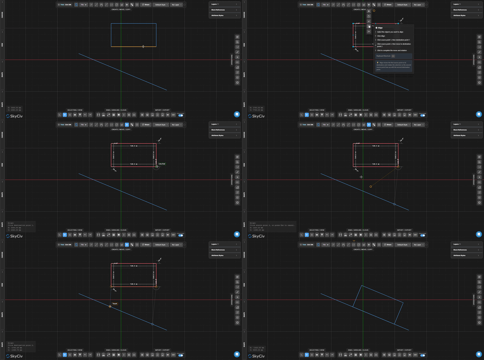
De Uitlijnen tool moves en rotates a selection in a single operation by matching two source points on the selection to two destination points on the drawing. Particularly powerful for snapping components into place when you have two known reference locations.
Stap voor stap
- 1Select the objects to align.
- 2Klik Uitlijnen in the Move dropdown.
- 3Klik source point 1 (on the selection), vervolgens destination point 1 (op het doek).
- 4Klik source point 2 (on the selection), then move to destination point 2.
- 5Click to complete – the selection is simultaneously translated and rotated so both point pairs coincide.
De volgende pop-up wordt dan weergegeven met de twee volgende vereiste invoer:: Align moves source point 1 to destination point 1, then rotates the entire selection so source point 2 lines up with destination point 2. Use snaps to pick exact points on existing geometry.
Je structuur onderdrukken en verschuiven Herhalen
Reflect selected objects across a user-defined mirror line
MI
De Je structuur onderdrukken en verschuiven Herhalen tool reflects selected objects across a mirror axis defined by two points. The original objects are replaced by their mirrored counterparts. To keep the originals, gebruik Spiegel kopie in plaats van.
[__INSERT_IMAGE__]
Stap voor stap
- 1Select the objects to mirror.
- 2Klik Je structuur onderdrukken en verschuiven Herhalen (or press MI) in the Move dropdown.
- 3Click to set the start point of the mirror line.
- 4Click to set the end point of the mirror line.
- 5The selection is reflected across the defined axis.
De volgende pop-up wordt dan weergegeven met de twee volgende vereiste invoer:: The mirror line can be at any angle. Snap to existing geometry for a precise axis. Gebruik Spiegel kopie when you need to keep both the original and the mirrored result.
Je structuur onderdrukken en verschuiven Herhalen
De Je structuur onderdrukken en verschuiven Herhalen toolbar group creates duplicates of selected objects – by displacement, spiegel, reeks, offset, or rotation. Select objects first, then activate the desired copy operation from the Copy dropdown.
Relatieve kopie
Copy selected objects and displace the copy by a user-defined vector
De Relatieve kopie tool duplicates selected objects and places the copy at an offset defined by picking a base point and a destination. The workflow is identical to Relative Move – but the originals stay in place.
[__INSERT_IMAGE__]
Stap voor stap
- 1Select the objects to copy.
- 2Klik Relatieve kopie in the Copy dropdown.
- 3Click anywhere on the canvas to set the basispunt.
- 4Move the mouse – a live preview of the copy follows the cursor.
- 5Click to place the copy, or type an exact distance and press Enter.
De volgende pop-up wordt dan weergegeven met de twee volgende vereiste invoer:: druk op Verschuiving+👇⨃ Glucovance kopen to toggle between Cartesisch en Polair input modes. You can place multiple copies by continuing to click – Draai de weergave zodat u eenvoudig de twee gemeenschappelijke spanten kunt selecteren met een selectie van links naar rechts Esc to exit.
Spiegel kopie
Create a mirrored duplicate while keeping the original objects
Verticale afschuiving van dode belasting
Spiegel kopie creates a reflected duplicate of selected objects across a user-defined axis, leaving the originals in place. Use this instead of Je structuur onderdrukken en verschuiven Herhalen when you need both the original and its reflection.
[__INSERT_IMAGE__]
Stap voor stap
- 1Select the objects to mirror-copy.
- 2Klik Spiegel kopie (or press Verticale afschuiving van dode belasting) in the Copy dropdown.
- 3Click to set the start point of the mirror line.
- 4Click to set the end point of the mirror line.
- 5A mirrored copy is created – the originals remain unchanged.
De volgende pop-up wordt dan weergegeven met de twee volgende vereiste invoer:: The mirror axis can be at any angle. Snap to existing geometry to define a precise axis. Gebruik Je structuur onderdrukken en verschuiven Herhalen if you want to replace the originals rather than keep them.
Kopieer array
Distribute copies of selected objects in a linear array pattern
AR
De Kopieer array tool distributes multiple copies of selected objects along a vector direction. The number of copies and total span are configured in the Vormen paneel, making it ideal for regularly spaced structural elements such as columns, vakwerken, and bolt groups.
[__INSERT_IMAGE__]
Stap voor stap
- 1Select the objects to array.
- 2Stel de copy count en span distance hebben we in de Vormen paneel.
- 3Klik Kopieer array (or press AR) in the Copy dropdown.
- 4Click to set the basispunt of the array.
- 5Move the mouse to set the direction, then click to create the copies.
De volgende pop-up wordt dan weergegeven met de twee volgende vereiste invoer:: Configure the copy count and span in the Vormen panel before activating the tool. For rotational arrays (cirkelvormige patronen), gebruik Kopiëren door rotatie in plaats van.
Offsetkopie
Create a parallel copy of lines or polylines at a specified perpendicular distance
O
De Offsetkopie tool creates a parallel duplicate of selected lines or polylines at a specified perpendicular distance. Equivalent to AutoCAD’s OFFSET command – commonly used for wall thickness, lane markings, and parallel structural members.
[__INSERT_IMAGE__]
Stap voor stap
- 1Select the lines or polylines to offset.
- 2Enter the gecompenseerde afstand hebben we in de Vormen paneel.
- 3Klik Offsetkopie (or press O) in the Copy dropdown.
- 4The offset copy is created parallel to the original at the specified distance.
De volgende pop-up wordt dan weergegeven met de twee volgende vereiste invoer:: Use a positief value to offset to one side and a negatief value for the other. The direction is relative to the orientation of the original line.
Kopiëren door rotatie
Create multiple rotated copies arranged around a center point
De Kopiëren door rotatie tool creates multiple copies of selected objects in a circular (polar) pattern around a center point. Useful for radially symmetric structures such as bolt groups on a flange or members in a circular truss.
[__INSERT_IMAGE__]
Stap voor stap
- 1Select the objects to copy by rotation.
- 2Stel de copy count en total rotation angle hebben we in de Vormen paneel.
- 3Klik Kopiëren door rotatie in the Copy dropdown.
- 4Click to set the rotation center point.
- 5Move the mouse to preview, then click to create the copies.
De volgende pop-up wordt dan weergegeven met de twee volgende vereiste invoer:: For evenly spaced copies around a full circle, set the angle to 360° and the count to the desired number. Configure both values in Vormen before activating the tool.
