
Chevron brace connection design to AISC 360 covers two joints. At each brace end, you check the bolts between the brace and the gusset plate for slip, bearing and tear-out, then block shear and tension rupture of both parts, and tension and buckling of the gusset on its Whitmore section. ビームで, you resolve the two brace forces at the gusset edge, then check the gusset-to-beam fillet welds, the gusset in shear and tension along that edge, and the beam web under the concentrated force.
このページは最初から最後まで 1 つの実際の例で動作します. Two WT7x41 braces at 60° meet at the underside of a W18x55 girder, and each carries 250 kip in tension or 250 圧縮時のキップ (LRFD). Each brace flange is bolted with ten 1 in A490-SC bolts to a 1/2 A572グレードで 50 gusset plate, which is welded to the girder flange with 3/16 in fillets on both sides. デザインはAISCへ 360-16, the AISC Manual 15th Edition and AISC Design Guide 29. すべての方程式は数値とともに書き出されます, AISC 計算シートと同じ順序で、 SkyCiv接続設計 モジュールはこの接続用に生成します.
What is a chevron brace connection?
A chevron brace, also called an inverted V brace, is a pair of diagonal braces that rise from the lower corners of a frame bay and meet at the middle of the beam above. The connection at the top joins both braces to the beam through a single gusset plate. In this example each brace is a WT, with its flange bolted flat to the gusset and its stem standing out, and the gusset is shop welded to the bottom flange of the girder.
Under lateral load one brace pulls and the other pushes, so the gusset passes a large horizontal force into the beam. Both brace lines meet at a work point on the beam’s centreline, half the beam depth below the gusset edge, and that offset puts a moment on the gusset-to-beam weld even though the gusset is centred on the work point. この例は、次の場所で直接確認できます。 chevron brace connection calculator. The same brace-to-gusset checks appear in the 垂直ブレース接続計算機 そしてその 膝装具接続計算機.
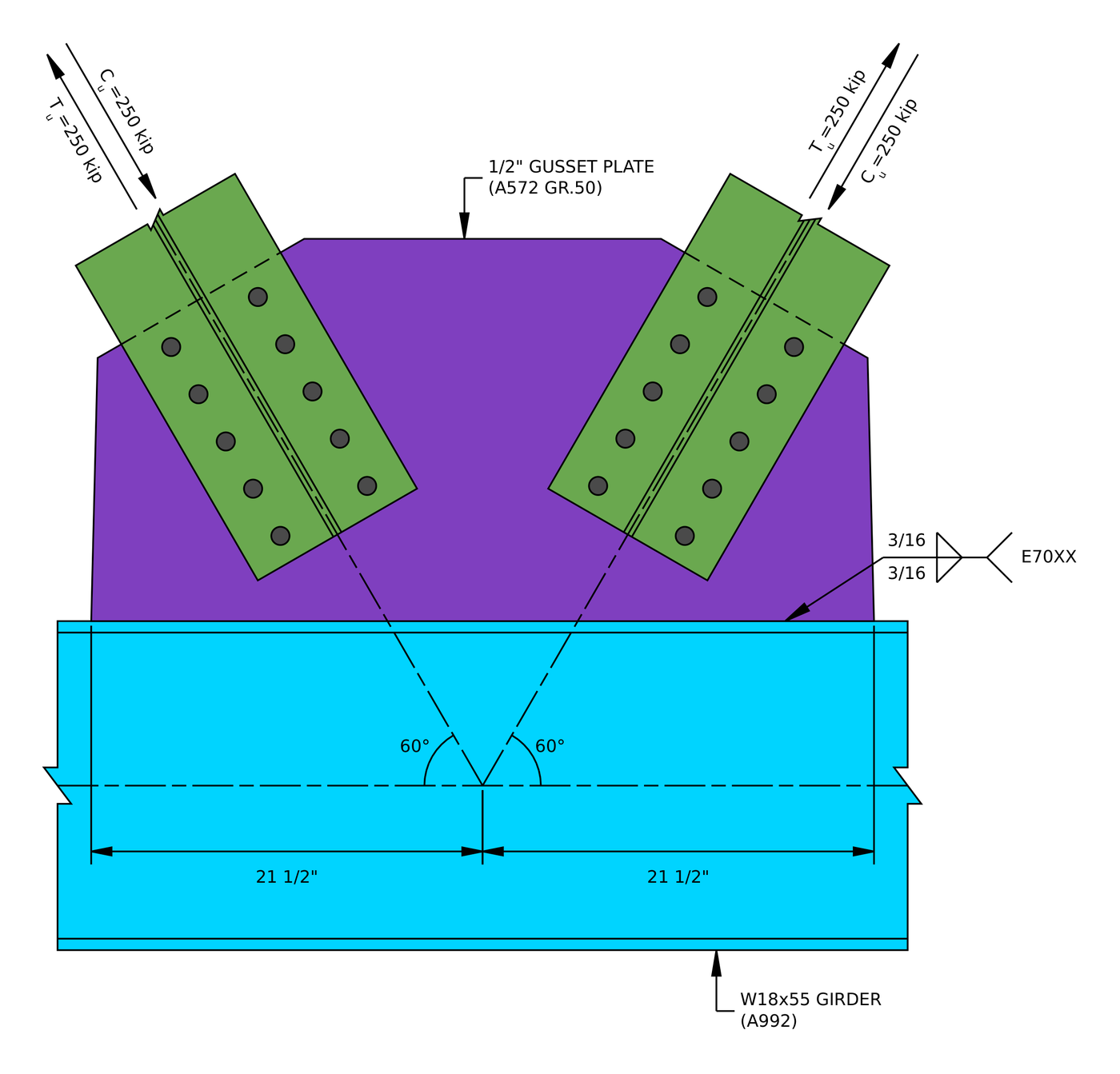
接続例の立面図. The brace lines meet on the girder centreline, and the gusset weld runs 21 1/2 in each side of that point.
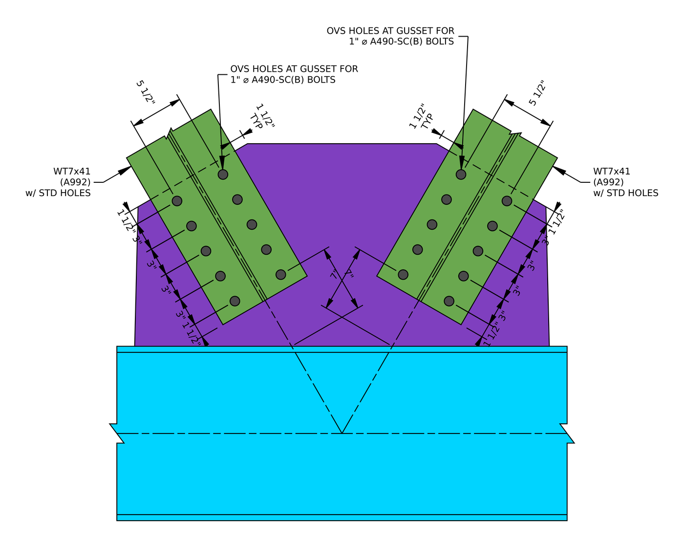
The brace connections. Each WT flange has two lines of five bolts at 3 in on a 5 1/2 ゲージ内, と 1 1/2 終わりの距離で, and the last bolts sit 7 in from the girder.
Chevron brace connection design: 一目でわかる手順
- Check the detailing limits at the brace bolts: ゲージ, 間隔とエッジの距離.
- Check the slip resistance of the slip-critical bolts.
- Check bolt bearing and tear-out on the gusset plate.
- Check bolt bearing and tear-out on the brace.
- Check block shear of the gusset plate.
- Check block shear of the brace.
- Check the gusset plate in tension on its Whitmore section.
- Check the brace in tension rupture with shear lag.
- Check the gusset plate in compression buckling.
- Check the minimum fillet weld size at the girder.
- Resolve the brace forces at the gusset edge and check the gusset-to-girder weld.
- Check the gusset plate in shear yielding along the girder.
- Check the gusset plate in tension yielding along the girder.
- Check the girder web for local crippling and local yielding.
この例の設計入力
設計コードはAISCです 360-16 LRFD. セクションのプロパティは AISC マニュアルからのものです. The two braces are identical and mirror each other about the work point, so Steps 1 に 9 are worked once and apply to both.
| アイテム | シンボル | 値 |
|---|---|---|
| Brace tension load (each brace) | [mathin] T_{u,br} [mathin] | 250 キップ |
| Brace compression load (each brace) | [mathin] C_{u,br} [mathin] | 250 キップ |
| 桁 | W18x55, A992 | |
| 桁深さ / ウェブの厚さ | [mathin] d_{g},\ t_{w,g} [mathin] | 18.1 に / 0.39 に |
| 桁フランジ幅 / 厚さ | [mathin] b_{f,g},\ t_{f,g} [mathin] | 7.53 に / 0.63 に |
| 桁部 / kdes | [mathin] A_{g},\ k_{des,g} [mathin] | 16.2 平方インチ / 1.03 に |
| 桁降伏量 / 引張応力 | [mathin] F_{y,g},\ F_{u,g} [mathin] | 50 KSI / 65 KSI |
| ブレース | WT7x41, A992 | |
| Brace area | [mathin] A_{br} [mathin] | 12 平方インチ |
| Brace flange width / 厚さ | [mathin] b_{f,br},\ t_{f,br} [mathin] | 10.1 に / 0.855 に |
| Brace stem thickness / 重心 | [mathin] t_{w,br},\ \bar{y} [mathin] | 0.51 に / 1.39 に |
| Brace slope from the girder | [mathin] \theta_{br} [mathin] | 60° |
| Brace unbraced length (gusset buckling length) | [mathin] L_{b,br} [mathin] | 7 に |
| Brace yield / 引張応力 | [mathin] F_{y,br},\ F_{u,br} [mathin] | 50 KSI / 65 KSI |
| 弾性率 | [mathin] E [mathin] | 29000 KSI |
| アイテム | シンボル | 値 |
|---|---|---|
| ガセットプレート | 1/2 に, A572 Grade 50 | |
| Gusset thickness | [mathin] t_{gp} [mathin] | 0.5 に |
| Gusset yield / 引張応力 | [mathin] F_{y,gp},\ F_{u,gp} [mathin] | 50 KSI / 65 KSI |
| ボルト | 1 A490-SCで, Class B surface | |
| ボルト径 | [mathin] d_{b} [mathin] | 1 に |
| Holes in brace / gusset | 標準 (STD) / 特大の (OVS) | |
| Bolt gage across the stem | [mathin] g_{a} [mathin] | 5.5 に |
| ボルト列 / 行間隔 | [mathin] n_{r},\ s_{r} [mathin] | 5 / 3 に |
| ボルトライン (コラム) | [mathin] n_{c} [mathin] | 2 |
| End distance on brace and gusset | [mathin] L_{ev} [mathin] | 1.5 に |
| Weld at the girder | 3/16 フィレで, both sides of the gusset, E70XX | |
| 溶接サイズ / フィラー強度 | [mathin] W,\ F_{EXX} [mathin] | 0.1875 に / 70 KSI |
| Weld length each side of the work point | [mathin] L_{w1},\ L_{w2} [mathin] | 21.5 に / 21.5 に |
| Total gusset length along the girder | [mathin] L_{WT} [mathin] | 43 に |
Each brace has ten bolts: two lines of five, one line on each side of the stem. The brace length on the gusset adds up from the drawing: 二 1.5 in end distances plus four 3 スペースで, 15 に. The inputs page also lists a 3 in bolt column spacing for the left brace and none for the right. It only enters the block shear equations multiplied by [mathin] (n_{c} – 2) = 0 [mathin], so it has no effect.
ステップ 1: Detailing limits at the brace bolts (AISC 360-16 J3.3, J3.4, J3.5)
ボルトのレイアウトは構築可能であり、強度方程式の背後にある仮定と一致する必要があります。. ボルトが近すぎると穴の間が裂ける, 近すぎるエッジが破れてしまう, and the gage across the stem has to leave room to fit and tighten the bolts on each side of it.
のために 1 ボルトの最小間隔は [mathin] 2\tfrac{2}{3} d_{b} = 2.667\,in [mathin] (J3.3) 最小エッジ距離は 1.25 に (表 J3.4). The WT has standard holes, それで 1.25 in applies to it directly. The gusset has oversized holes, したがって、テーブル J3.5 の増分は 1/8 in raises its minimum end distance to 1.375 に.
| ディテールの限界 | リミット (に) | 実際 (に) | DCR | 結果 |
|---|---|---|---|---|
| 最小ボルトゲージ | 4.175 | 5.500 | 0.759 | 合格 |
| 最小ボルト列間隔 | 2.667 | 3.000 | 0.889 | 合格 |
| 最大ボルト列間隔 | 6.000 | 3.000 | 0.500 | 合格 |
| Gusset plate minimum vertical edge distance | 1.375 | 1.500 | 0.917 | 合格 |
| Brace minimum vertical edge distance | 1.250 | 1.500 | 0.833 | 合格 |
| Brace minimum horizontal edge distance | 1.250 | 2.313 | 0.540 | 合格 |
The horizontal edge distance on the WT flange is half of what is left after the gage. Using the flange width as a fraction, 10 1/8 に, あれは (10.125 − 5.5)/2 = 2.3125 に. 最小制限の場合、比率は実際の制限値を超えます, そして最大値の場合、それは実際の制限を超えています. The governing row is the gusset end distance with its oversized hole increment:
[math] DCR = \frac{d}{c} = \frac{(1.375)}{(1.5)} = 0.91667 [math]
DCR = 0.917 < 1.0, わかった
ステップ 2: Slip resistance of the bolts (AISC 360-16 J3.8)
The gusset has oversized holes, およびAISC 360-16 J3.2 allows oversized holes only in slip-critical joints. So the bolts are pretensioned and the brace force is carried by friction between the WT flange and the gusset. The check is that the joint does not slip under the factored load.
どこ [mathin] \phi = 0.85 [mathin] 特大穴用, [mathin] \mu = 0.5 [mathin] for a Class B surface, [mathin] D_{u} = 1.13 [mathin], [mathin] h_{f} = 1 [mathin] 充填剤がないので, [mathin] T_{b} = 64\,kip [mathin] のために 1 A490ボルトで (表 J3.1), [mathin] N_{s} = 1 [mathin] すべり面, [mathin] n_{r} = 5 [mathin] そして [mathin] n_{c} = 2 [mathin]:
[math] \phi R_{n} = \phi\, \mu\, D_{u}\, h_{f}\, T_{b}\, N_{s}\, n_{r}\, n_{c} [math]
[math] \phi R_{n} = (0.85) \times (0.5) \times (1.13) \times (1) \times (64\,kip) \times (1) \times (5) \times (2) [math]
[math] \phi R_{n} = 307.36\,kip [math]
DCR = 250 キップ / 307.36 キップ = 0.813 < 1.0, わかった
The same check covers tension and compression, because the brace force is 250 どちらにしてもキップ.
ステップ 3: Bolt bearing and tear-out on the gusset plate (AISC 360-16 J3.10)
Slip-critical bolts still have to be checked for bearing, because if the joint does slip the bolts end up bearing on the sides of their holes. In tension the brace pulls the bolts away from the girder, so they bear on the gusset toward its outer edge. The bolt nearest that edge has the least material in front of it.
The gusset hole is oversized, [mathin] d_{h} = 1.25\,in [mathin]. Clear distance for the end bolt, と [mathin] L_{ev} = 1.5\,in [mathin]:
[math] l_{c1} = L_{ev} – \frac{d_{h}}{2} = (1.5\,in) – \frac{(1.25\,in)}{2} = 0.875\,in [math]
ボルト間の明確な距離, と [mathin] s_{r} = 3\,in [mathin]:
[math] l_{c2} = s_{r} – d_{h} = (3\,in) – (1.25\,in) = 1.75\,in [math]
どこ [mathin] t_{gp} = 0.5\,in [mathin], [mathin] F_{u,gp} = 65\,ksi [mathin], [mathin] n_{r} = 5 [mathin], [mathin] n_{c} = 2 [mathin], [mathin] d_{b} = 1\,in [mathin] そして [mathin] \phi = 0.75 [mathin]:
[math] \phi R_{n,tearout} = \phi \left[ \min\left(1.2\, l_{c1},\, 2.4\, d_{b}\right) t_{gp} F_{u,gp}\, n_{c} + \min\left(1.2\, l_{c2},\, 2.4\, d_{b}\right) t_{gp} F_{u,gp}\, n_{c} \left( n_{r} – 1 \right) \right] [math]
[math] \phi R_{n,tearout} = (0.75) \times \left[ \min\left(1.2 \times (0.875\,in),\, 2.4 \times (1\,in)\right) \times (0.5\,in) \times (65\,ksi) \times (2) + \min\left(1.2 \times (1.75\,in),\, 2.4 \times (1\,in)\right) \times (0.5\,in) \times (65\,ksi) \times (2) \times ((5) – 1) \right] [math]
[math] \phi R_{n,tearout} = 460.69\,kip [math]
DCR = 250 キップ / 460.69 キップ = 0.543 < 1.0, わかった
Tear-out governs every bolt, because the oversized hole eats into the clear distance: 1.2 lc is below 2.4 db for both the end bolts and the inner bolts. In compression the bolts bear toward the girder instead, where there is more gusset, so tension is the case that matters.
ステップ 4: Bolt bearing and tear-out on the brace (AISC 360-16 J3.10)
The same check applies to the WT flange. In tension the brace is pulled away from the girder, so its bolts bear toward the end of the WT nearest the girder.
The WT has standard holes, [mathin] d_{h} = 1.125\,in [mathin]:
[math] l_{c1} = L_{ev} – \frac{d_{h}}{2} = (1.5\,in) – \frac{(1.125\,in)}{2} = 0.9375\,in [math]
[math] l_{c2} = s_{r} – d_{h} = (3\,in) – (1.125\,in) = 1.875\,in [math]
どこ [mathin] t_{f,br} = 0.855\,in [mathin] そして [mathin] F_{u,br} = 65\,ksi [mathin]:
[math] \phi R_{n,tearout} = \phi \left[ \min\left(1.2\, l_{c1},\, 2.4\, d_{b}\right) t_{f,br} F_{u,br}\, n_{c} + \min\left(1.2\, l_{c2},\, 2.4\, d_{b}\right) t_{f,br} F_{u,br}\, n_{c} \left( n_{r} – 1 \right) \right] [math]
[math] \phi R_{n,tearout} = (0.75) \times \left[ \min\left(1.2 \times (0.9375\,in),\, 2.4 \times (1\,in)\right) \times (0.855\,in) \times (65\,ksi) \times (2) + \min\left(1.2 \times (1.875\,in),\, 2.4 \times (1\,in)\right) \times (0.855\,in) \times (65\,ksi) \times (2) \times ((5) – 1) \right] [math]
[math] \phi R_{n,tearout} = 844.05\,kip [math]
DCR = 250 キップ / 844.05 キップ = 0.296 < 1.0, わかった
の 0.855 in WT flange is 1.7 times as thick as the gusset, and the smaller standard hole leaves more clear distance, so the brace has nearly twice the bearing strength of the gusset.
ステップ 5: Block shear of the gusset plate (AISC 360-16 J4.3)
A block of the gusset can tear out around the bolts: shear along the bolt lines to the gusset’s edge, plus tension across the bolt group. With two bolt lines there are two shapes to check. The L pattern shears along one bolt line and tears across both lines to the gusset’s side edge. The U pattern shears along both bolt lines and tears across between them. The weaker of the two governs.
Lパターン
張力のあるネットエリア, across the 5.5 in gage plus the gusset edge distance beyond the far bolt line, [mathin] L_{eh,gp} = 2.3\,in [mathin]. That edge distance is the same as the WT’s own edge distance, (10.1 − 5.5)/2. The tension path crosses one full hole and one half hole, and each hole adds 1/16 パンチ時にダメージを受ける (B4.3):
[math] A_{nt} = t_{gp} \left[ (n_{c}-2)\, s_{c} + g_{a} + L_{eh,gp} – (n_{c} – 0.5) \left( d_{h} + 0.0625\,in \right) \right] [math]
[math] A_{nt} = (0.5\,in) \times \left[ ((2)-2) \times (3\,in) + (5.5\,in) + (2.3\,in) – ((2) – 0.5) \times ((1.25\,in) + (0.0625\,in)) \right] = 2.9156\,in^{2} [math]
総せん断面積, along one bolt line from the gusset’s edge to the farthest bolt:
[math] A_{gv} = t_{gp} \left[ L_{ev} + (n_{r}-1)\, s_{r} \right] = (0.5\,in) \times \left[ (1.5\,in) + ((5)-1) \times (3\,in) \right] = 6.75\,in^{2} [math]
せん断時の正味面積. The report writes the shear length as the 15 in brace length on the gusset, [mathin] L_{br,gp} [mathin], less one end distance, which is the same 13.5 in as in the gross area:
[math] A_{nv} = t_{gp} \left[ L_{br,gp} – L_{ev} – (n_{r} – 0.5)\left( d_{h} + 0.0625\,in \right) \right] [math]
[math] A_{nv} = (0.5\,in) \times \left[ (15\,in) – (1.5\,in) – ((5) – 0.5) \times ((1.25\,in) + (0.0625\,in)) \right] = 3.7969\,in^{2} [math]
ブロックせん断強度, と [mathin] U_{bs} = 1 [mathin] because the tension stress is uniform, [mathin] F_{u,gp} = 65\,ksi [mathin], [mathin] F_{y,gp} = 50\,ksi [mathin] そして [mathin] \phi = 0.75 [mathin]:
[math] \phi R_{n} = \phi \left( 0.6\, F_{u,gp} A_{nv} + U_{bs} F_{u,gp} A_{nt} \le 0.6\, F_{y,gp} A_{gv} + U_{bs} F_{u,gp} A_{nt} \right) [math]
[math] \phi R_{n} = (0.75) \times \left( 0.6 \times (65\,ksi) \times (3.7969\,in^{2}) + (1) \times (65\,ksi) \times (2.9156\,in^{2}) \le 0.6 \times (50\,ksi) \times (6.75\,in^{2}) + (1) \times (65\,ksi) \times (2.9156\,in^{2}) \right) [math]
[math] \phi R_{n} = 253.2\,kip [math]
Uパターン
張力のあるネットエリア, between the two bolt lines only, which crosses one hole in total (a half hole at each line):
[math] A_{nt} = t_{gp} \left[ (n_{c}-2)\, s_{c} + g_{a} – (n_{c} – 1) \left( d_{h} + 0.0625\,in \right) \right] [math]
[math] A_{nt} = (0.5\,in) \times \left[ ((2)-2) \times (3\,in) + (5.5\,in) – ((2) – 1) \times ((1.25\,in) + (0.0625\,in)) \right] = 2.0937\,in^{2} [math]
せん断面積の総面積と正味面積, now along both bolt lines:
[math] A_{gv} = 2\, t_{gp} \left[ L_{ev} + (n_{r}-1)\, s_{r} \right] = 2 \times (0.5\,in) \times \left[ (1.5\,in) + ((5)-1) \times (3\,in) \right] = 13.5\,in^{2} [math]
[math] A_{nv} = 2\, t_{gp} \left[ (n_{r}-1)\, s_{r} + L_{ev} – (n_{r} – 0.5)\left( d_{h} + 0.0625\,in \right) \right] [math]
[math] A_{nv} = 2 \times (0.5\,in) \times \left[ ((5)-1) \times (3\,in) + (1.5\,in) – ((5) – 0.5) \times ((1.25\,in) + (0.0625\,in)) \right] = 7.5937\,in^{2} [math]
[math] \phi R_{n} = (0.75) \times \left( 0.6 \times (65\,ksi) \times (7.5937\,in^{2}) + (1) \times (65\,ksi) \times (2.0937\,in^{2}) \le 0.6 \times (50\,ksi) \times (13.5\,in^{2}) + (1) \times (65\,ksi) \times (2.0937\,in^{2}) \right) [math]
[math] \phi R_{n} = 324.19\,kip [math]
ガバナブロックせん断
[math] \phi R_{n} = \min\left( \phi R_{n},\, \phi R_{n} \right) = \min\left( (253.2\,kip),\, (324.19\,kip) \right) = 253.2\,kip [math]
DCR = 250 キップ / 253.2 キップ = 0.987 < 1.0, わかった
This is the closest check on the brace side. せん断面が 1 つしかないため、L パターンが支配します, and net shear rupture governs within it: の 1 1/4 in oversized holes take 5.9 in out of the 13.5 in shear length.
ステップ 6: Block shear of the brace (AISC 360-16 J4.3)
The WT flange can tear out too. Here the blocks are on the outside: each bolt line shears along its length to the end of the WT, and tears across to the flange tip beside it. Two L-shaped blocks fail together, one each side of the stem.
張力のあるネットエリア, from each bolt line out to the flange tip, with the flange width less the gage and one hole in total, [mathin] d_{h} = 1.125\,in [mathin]:
[math] A_{nt} = t_{f,br} \left[ b_{f,br} – g_{a} – (n_{c} – 1) \left( d_{h} + 0.0625\,in \right) \right] [math]
[math] A_{nt} = (0.855\,in) \times \left[ (10.1\,in) – (5.5\,in) – ((2) – 1) \times ((1.125\,in) + (0.0625\,in)) \right] = 2.9177\,in^{2} [math]
[math] A_{gv} = 2\, t_{f,br} \left[ L_{ev} + (n_{r}-1)\, s_{r} \right] = 2 \times (0.855\,in) \times \left[ (1.5\,in) + ((5)-1) \times (3\,in) \right] = 23.085\,in^{2} [math]
[math] A_{nv} = 2\, t_{f,br} \left( L_{ev} + (n_{r}-1)\, s_{r} – (n_{r} – 0.5)\left( d_{h} + 0.0625\,in \right) \right) [math]
[math] A_{nv} = 2 \times (0.855\,in) \times \left( (1.5\,in) + ((5)-1) \times (3\,in) – ((5) – 0.5) \times ((1.125\,in) + (0.0625\,in)) \right) = 13.947\,in^{2} [math]
と [mathin] F_{u,br} = 65\,ksi [mathin], [mathin] F_{y,br} = 50\,ksi [mathin], [mathin] U_{bs} = 1 [mathin] そして [mathin] \phi = 0.75 [mathin]:
[math] \phi R_{n} = \phi \left( 0.6\, F_{u,br} A_{nv} + U_{bs} F_{u,br} A_{nt} \le 0.6\, F_{y,br} A_{gv} + U_{bs} F_{u,br} A_{nt} \right) [math]
[math] \phi R_{n} = (0.75) \times \left( 0.6 \times (65\,ksi) \times (13.947\,in^{2}) + (1) \times (65\,ksi) \times (2.9177\,in^{2}) \le 0.6 \times (50\,ksi) \times (23.085\,in^{2}) + (1) \times (65\,ksi) \times (2.9177\,in^{2}) \right) [math]
[math] \phi R_{n} = 550.19\,kip [math]
DCR = 250 キップ / 550.19 キップ = 0.454 < 1.0, わかった
ステップ 7: Gusset plate in tension on the Whitmore section (AISC 360-16 J4.1)
The brace force enters the gusset through the bolts and spreads out as it travels along the plate. The Whitmore section is the effective width that takes that force at the last bolt row: lines drawn at 30° from the outer bolts of the first row, measured across the last row (AISC マニュアル部分 9, 図. 9-1). The gusset must not yield on that width, and it must not rupture on that width less the holes.
ホイットモア幅
The bolt group is [mathin] L_{br} = (n_{r}-1)\, s_{r} = 12\,in [mathin] 長いです, and its two lines are [mathin] W_{br} = g_{a} = 5.5\,in [mathin] apart. In the report, [mathin] W [mathin] in this step is the Whitmore width, not the weld size:
[math] W = 2\, L_{br} \tan(\theta) + W_{br} = 2 \times (12\,in) \times \tan((30)) + (5.5\,in) = 19.356\,in [math]
The gusset here is large enough to take the full 30° spread on both sides, so no part of the Whitmore width runs off the plate.
張力降伏 (Eq. J4-1)
と [mathin] \phi = 0.9 [mathin], [mathin] F_{y,gp} = 50\,ksi [mathin] そして [mathin] t_{gp} = 0.5\,in [mathin]:
[math] \phi R_{n,ty} = \phi\, F_{y,gp}\, t_{gp}\, W = (0.9) \times (50\,ksi) \times (0.5\,in) \times (19.356\,in) = 435.52\,kip [math]
引張破断 (Eq. J4-2)
The net width removes the two oversized holes in the last row, [mathin] d_{h} = 1.25\,in [mathin], と [mathin] \phi = 0.75 [mathin] そして [mathin] F_{u,gp} = 65\,ksi [mathin]:
[math] \phi R_{n,tr} = \phi\, F_{u,gp}\, t_{gp} \left[ W – n_{c}\left( d_{h} + 0.0625\,in \right) \right] [math]
[math] \phi R_{n,tr} = (0.75) \times (65\,ksi) \times (0.5\,in) \times \left[ (19.356\,in) – (2) \times ((1.25\,in) + (0.0625\,in)) \right] = 407.83\,kip [math]
[math] \phi R_{n} = \min\left( \phi R_{n,ty},\, \phi R_{n,tr} \right) = \min\left( (435.52\,kip),\, (407.83\,kip) \right) = 407.83\,kip [math]
DCR = 250 キップ / 407.83 キップ = 0.613 < 1.0, わかった
ステップ 8: Brace in tension rupture with shear lag (AISC 360-16 D3, J4.1)
Only the flange of the WT is bolted, so the force in the stem has to flow into the flange near the connection. That uneven stress is shear lag, and AISC handles it with the factor U, which reduces the net area.
From Table D3.1, 場合 2, with the WT’s centroid [mathin] \bar{y} = 1.39\,in [mathin] measured from the bolted face of the flange and the connection length [mathin] (n_{r} – 1)\, s_{r} = 12\,in [mathin]:
[math] U = 1 – \frac{\bar{y}}{(n_{r} – 1)\, s_{r}} = 1 – \frac{(1.39\,in)}{((5) – 1) \times (3\,in)} = 0.88421 [math]
The net area removes the two holes in one row from the flange. どこ [mathin] A_{br} = 12\,in^{2} [mathin], [mathin] d_{h} = 1.125\,in [mathin], [mathin] t_{f,br} = 0.855\,in [mathin], [mathin] F_{u,br} = 65\,ksi [mathin] そして [mathin] \phi = 0.75 [mathin]:
[math] \phi R_{n,tr} = \phi\, F_{u,br}\, U \left[ A_{br} – n_{c}\left( d_{h} + 0.0625\,in \right) t_{f,br} \right] [math]
[math] \phi R_{n,tr} = (0.75) \times (65\,ksi) \times (0.88421) \times \left[ (12\,in^{2}) – (2) \times ((1.125\,in) + (0.0625\,in)) \times (0.855\,in) \right] = 429.73\,kip [math]
DCR = 250 キップ / 429.73 キップ = 0.582 < 1.0, わかった
The long bolt group keeps U high. Gross yielding of the brace is part of the member design, so it is not repeated here.
ステップ 9: Gusset plate in compression buckling (AISC 360-16 J4.4, E3)
When a brace is in compression it pushes the gusset toward the girder. The strip of gusset between the last bolt row and the girder flange can buckle out of plane, so it is checked as a column with the Whitmore width as its cross section.
The buckling length is the 7 in shown on the drawing, from the bolt row nearest the girder to the girder flange, measured along the brace. The report labels it the brace unbraced length, [mathin] L_{b,br} = 7\,in [mathin]. The gusset is welded to the girder on one edge only and its free end can sway out of plane with the braces, so the report takes [mathin] K = 1.2 [mathin]. For a solid rectangle, [mathin] r = t_{gp}/\sqrt{12} = 0.14434\,in [mathin]:
[math] \frac{KL}{r} = \frac{(1.2) \times (7\,in)}{(0.5\,in)/\sqrt{12}} = 58.197 [math]
以来 [mathin] KL/r \gt 25 [mathin], J4.4 sends the check to Chapter E. Elastic buckling stress:
[math] F_{e} = \frac{\pi^{2} E}{\left( \frac{KL}{r} \right)^{2}} = \frac{\pi^{2} \times (29000\,ksi)}{((58.197))^{2}} = 84.508\,ksi [math]
[math] 4.71 \sqrt{\frac{E}{F_{y}}} = 113.43 [math]
以来 [mathin] KL/r \le 4.71\sqrt{E/F_{y}} [mathin], the inelastic equation E3-2 applies:
[math] F_{cr} = \left( 0.658^{\frac{F_{y,gp}}{F_{e}}} \right) F_{y,gp} = \left( 0.658^{\frac{(50\,ksi)}{(84.508\,ksi)}} \right) \times (50\,ksi) = 39.032\,ksi [math]
と [mathin] \phi = 0.9 [mathin] and the Whitmore width [mathin] W = 19.356\,in [mathin]:
[math] \phi R_{n} = \phi\, F_{cr}\, t_{gp}\, W = (0.9) \times (39.032\,ksi) \times (0.5\,in) \times (19.356\,in) = 339.98\,kip [math]
DCR = 250 キップ / 339.98 キップ = 0.735 < 1.0, わかった
Slenderness costs about 22% of the yield stress here. Moving the bolts closer to the girder shortens L, and a thicker gusset raises r directly.
ステップ 10: Minimum fillet weld size at the girder (AISC 360-16 J2.2b)
A fillet weld that is too small for the parts it joins can crack as it cools, because the thicker part draws heat out of it too fast. Table J2.4 sets the minimum by the thinner part joined. Here that is the 1/2 in gusset, which falls in the over 1/4 に 1/2 in band, so the minimum is 3/16 に.
| ディテールの限界 | リミット (に) | 実際 (に) | DCR | 結果 |
|---|---|---|---|---|
| Minimum fillet weld size | 0.188 | 0.188 | 1.000 | 合格 |
[math] DCR = \frac{d}{c} = \frac{(0.188)}{(0.188)} = 1 [math]
DCR = 1.000, わかった
の比率 1.000 here only says the 3/16 in weld is exactly the smallest size allowed. Whether it is strong enough is the next step.
ステップ 11: Gusset-to-girder weld (AISC 360-16 J2.4, AISC 設計ガイド 29)
The gusset is welded to the girder flange with a 3/16 in fillet on each side. The two brace forces reach the gusset edge as a normal force, a shear along the girder and a moment, and the weld carries all three together. This step resolves the brace forces at the gusset edge, finds the worst load on the weld, and checks the weld against it.
溶接サイズの母材制限 (AISC マニュアル Eq. 9-2)
The gusset has a weld on both faces, so half its thickness backs each weld. と [mathin] t_{f,g} = 0.63\,in [mathin], [mathin] F_{u,g} = 65\,ksi [mathin], [mathin] t_{gp} = 0.5\,in [mathin] そして [mathin] F_{u,gp} = 65\,ksi [mathin]:
[math] D_{max} = \frac{t_{f,g} F_{u,g} \le \frac{t_{gp}}{2} F_{u,gp}}{3.09\,kip/in \times F_{EXX}/F_{E70XX}} = \frac{(0.63\,in) \times (65\,ksi) \le (0.25\,in) \times (65\,ksi)}{(3.09\,kip/in) \times (1)} = 5.2589 [math]
あれは 5.2589 16分の1, 約 0.329 に, so the full 3/16 in weld counts.
有効溶接長さ
The gusset runs [mathin] L_{WT} = 43\,in [mathin] along the girder. Each of the two weld lines is reduced by 2W for the ends:
[math] L_{w} = 2 \left[ L_{WT} – 2W \right] = 2 \times \left[ (43\,in) – 2 \times (0.1875\,in) \right] = 85.25\,in [math]
Forces at the gusset edge
Each brace force splits into a component perpendicular to the girder, [mathin] P \sin\theta [mathin], and one along it, [mathin] P \cos\theta [mathin]. The report takes the normal force as the largest that any one brace delivers, 張力または圧縮:
[math] N_{br} = \max\left[ T_{u,l,br} \sin(\theta_{l,br}),\, C_{u,l,br} \sin(\theta_{l,br}),\, T_{u,r,br} \sin(\theta_{r,br}),\, C_{u,r,br} \sin(\theta_{r,br}) \right] = (250\,kip) \times \sin((60)) = 216.51\,kip [math]
The shear along the girder is the sum of the two horizontal components with one brace in tension and the other in compression, which is the usual lateral load case for a chevron. Both components then point the same way:
[math] V_{br} = \max\left[ T_{u,l,br} \cos(\theta_{l,br}) + C_{u,r,br} \cos(\theta_{r,br}),\, C_{u,l,br} \cos(\theta_{l,br}) + T_{u,r,br} \cos(\theta_{r,br}) \right] [math]
[math] V_{br} = (250\,kip) \times \cos((60)) + (250\,kip) \times \cos((60)) = 250\,kip [math]
In that tension and compression case the two vertical components cancel. Pairing the 250 kip shear with a full 216.51 kip normal force from one brace is an envelope that covers unequal brace forces as well.
The moment has two parts, following AISC Design Guide 29, 例 5.9. The first is the normal force times its offset from the middle of the weld, which is zero here because the gusset runs 21.5 in each side of the work point. The second comes from the shear. The horizontal brace forces meet at the work point on the girder centreline, [mathin] d_{g}/2 = 9.05\,in [mathin] below the gusset edge, so moving them up to the edge adds [mathin] V_{br}\, d_{g}/2 [mathin]:
[math] M_{br} = \frac{N_{br} \left| L_{w1} – L_{w2} \right|}{2} + \frac{V_{br}\, d_{g}}{2} = \frac{(216.51\,kip) \times |(21.5\,in) – (21.5\,in)|}{2} + \frac{(250\,kip) \times (18.1\,in)}{2} = 188.54\,kip{\cdot}ft [math]
あれは 2262.5 チキンイン. The moment adds to the normal force at one end of the weld and subtracts at the other. The report turns the moment into an equivalent normal force using the plastic section modulus of the two weld lines, [mathin] L_{w}^{2}/8 [mathin], which gives the peak normal load:
[math] N_{br,T} = \frac{8\, M_{br}}{L_{w}} + N_{br} = \frac{8 \times (188.54\,kip{\cdot}ft)}{(85.25\,in)} + (216.51\,kip) = 428.82\,kip [math]
The moment is converted to kip-in (× 12) inside that fraction. The resultant at the peak and its angle to the weld axis:
[math] R = \sqrt{\left( N_{br,T} \right)^{2} + \left( V_{br} \right)^{2}} = \sqrt{((428.82\,kip))^{2} + ((250\,kip))^{2}} = 496.38\,kip [math]
[math] \theta = \tan^{-1}\left| \frac{N_{br,T}}{V_{br}} \right| = \tan^{-1}\left| \frac{(428.82\,kip)}{(250\,kip)} \right| = 59.758 [math]
Weld ductility factor
The load on the weld is not even. It peaks at one end and falls almost to nothing at the other. Fillet welds have limited ductility, so AISC Design Guide 29 and AISC Manual Part 13 design a gusset edge weld for the larger of the peak load and 1.25 times the average of the peak and minimum loads. の 1.25 lets the weld redistribute load before it fractures.
At the low-stress end the bending subtracts from the normal force:
[math] N_{br,min} = \left| N_{br} – \frac{8\, M_{br}}{L_{w}} \right| = \left| (216.51\,kip) – \frac{8 \times (188.54\,kip{\cdot}ft)}{(85.25\,in)} \right| = 4.1896\,kip [math]
[math] R_{min} = \sqrt{\left( N_{br,min} \right)^{2} + \left( V_{br} \right)^{2}} = \sqrt{((4.1896\,kip))^{2} + ((250\,kip))^{2}} = 250.04\,kip [math]
[math] R_{w} = \max\left( R,\, 1.25\, \frac{R + R_{min}}{2} \right) = \max\left( (496.38\,kip),\, 1.25 \times \frac{(496.38\,kip) + (250.04\,kip)}{2} \right) = 496.38\,kip [math]
The averaged value is 466.51 キップ, so the peak governs.
溶接強度 (Eq. J2-4)
The resultant is at 59.758° to the weld, so the directional factor [mathin] 1 + 0.5 \sin^{1.5}\theta [mathin] adds about 40% to the strength. と [mathin] \phi = 0.75 [mathin] そして [mathin] F_{EXX} = 70\,ksi [mathin]:
[math] \phi R_{n} = \phi\, 0.6\, F_{EXX} \frac{\sqrt{2}}{2} \left( W \le \frac{D_{max}}{16} \right) \left[ 1 + 0.5 \left( \sin\theta \right)^{1.5} \right] L_{w} [math]
[math] \phi R_{n} = (0.75) \times 0.6 \times (70\,ksi) \times \frac{\sqrt{2}}{2} \times \left( (0.1875\,in) \le \frac{(5.2589)}{(16)} \right) \times \left[ 1 + 0.5 \times (\sin(59.758))^{1.5} \right] \times (85.25\,in) [math]
[math] \phi R_{n} = 498.98\,kip [math]
DCR = 496.38 キップ / 498.98 キップ = 0.995 < 1.0, わかった
これは接続全体の管理チェックです. Almost half of the peak normal load, 212.31 キップ, comes from the moment, and that moment exists only because the work point is 9.05 in below the weld. The base metal would allow a weld up to about 5/16 に, so a 1/4 in fillet is the simplest way to gain margin.
ステップ 12: Gusset plate in shear yielding along the girder (AISC 360-16 J4.2)
The horizontal force, [mathin] V_{br} = 250\,kip [mathin], passes through the gusset’s welded edge as shear. The gross section along that edge must not yield.
と [mathin] L_{WT} = 43\,in [mathin], [mathin] t_{gp} = 0.5\,in [mathin], [mathin] F_{y,gp} = 50\,ksi [mathin] そして [mathin] \phi = 1 [mathin]:
[math] A_{gv} = L_{WT}\, t_{gp} = (43\,in) \times (0.5\,in) = 21.5\,in^{2} [math]
[math] \phi R_{n,sy} = \phi\, 0.6\, F_{y,gp} A_{gv} = (1) \times 0.6 \times (50\,ksi) \times (21.5\,in^{2}) = 645\,kip [math]
DCR = 250 キップ / 645 キップ = 0.388 < 1.0, わかった
ステップ 13: Gusset plate in tension yielding along the girder (AISC 360-16 J4.1)
The normal force and the moment put the gusset’s welded edge in tension, highest at one end. Following AISC Design Guide 29, 例 5.3, the report adds the two as normal stresses on the edge and turns the peak back into an equivalent force over the full edge.
The normal stress is [mathin] N/(t\,l) + M/(t\,l^{2}/4) [mathin]. Multiplying by [mathin] t\,l [mathin], と [mathin] l = L_{WT} = 43\,in [mathin]:
[math] N_{e} = \left| N_{br} \right| + \frac{4 \left| M_{br} \right|}{L_{WT}} = |(216.51\,kip)| + \frac{4 \times |(188.54\,kip{\cdot}ft)|}{(43\,in)} = 426.97\,kip [math]
This is slightly below the weld’s 428.82 kip because it uses the 43 in gusset edge rather than the 85.25 in of effective weld split over two lines. と [mathin] \phi = 0.9 [mathin]:
[math] \phi R_{n,ty} = \phi\, F_{y,gp}\, t_{gp}\, L_{WT} = (0.9) \times (50\,ksi) \times (0.5\,in) \times (43\,in) = 967.5\,kip [math]
DCR = 426.97 キップ / 967.5 キップ = 0.441 < 1.0, わかった
ステップ 14: Girder web local crippling and local yielding (AISC 360-16 J10.3, J10.2)
The gusset delivers a concentrated force to the girder flange over its 43 長さで. When the braces push up on the girder, the girder web above the gusset can yield locally or crumple (cripple). The demand is the peak normal load from Step 11, [mathin] N_{br,T} = 428.82\,kip [mathin].
Web ローカルの機能不全 (Eq. J10-4)
と [mathin] \phi = 0.75 [mathin], [mathin] t_{w,g} = 0.39\,in [mathin], ベアリングの長さ [mathin] L_{WT} = 43\,in [mathin], [mathin] d_{g} = 18.1\,in [mathin], [mathin] t_{f,g} = 0.63\,in [mathin], [mathin] F_{y,g} = 50\,ksi [mathin] そして [mathin] Q_{f} = 1 [mathin]:
[math] \phi R_{n,wlc} = \phi\, 0.8 \left( t_{w,g} \right)^{2} \left[ 1 + 3 \left( \frac{L_{WT}}{d_{g}} \right) \left( \frac{t_{w,g}}{t_{f,g}} \right)^{1.5} \right] \sqrt{\frac{E\, F_{y,g}\, t_{f,g}}{t_{w,g}}}\, Q_{f} [math]
[math] \phi R_{n,wlc} = (0.75) \times 0.8 \times ((0.39\,in))^{2} \times \left[ 1 + 3 \times \left( \frac{(43\,in)}{(18.1\,in)} \right) \times \left( \frac{(0.39\,in)}{(0.63\,in)} \right)^{1.5} \right] \times \sqrt{\frac{(29000\,ksi) \times (50\,ksi) \times (0.63\,in)}{(0.39\,in)}} \times (1) [math]
[math] \phi R_{n,wlc} = 624.51\,kip [math]
Web ローカル譲歩 (Eq. J10-2)
The force spreads through the flange and fillet on a 2.5:1 slope on each side, so the web yields over [mathin] 5k + l_{b} [mathin]. と [mathin] \phi = 1 [mathin] そして [mathin] k_{des,g} = 1.03\,in [mathin]:
[math] \phi R_{n,wly} = \phi\, F_{y,g}\, t_{w,g} \left( 5\, k_{des,g} + L_{WT} \right) = (1) \times (50\,ksi) \times (0.39\,in) \times \left( 5 \times (1.03\,in) + (43\,in) \right) = 938.92\,kip [math]
[math] \phi R_{n} = \min\left( \phi R_{n,wlc},\, \phi R_{n,wly} \right) = \min\left( (624.51\,kip),\, (938.92\,kip) \right) = 624.51\,kip [math]
DCR = 428.82 キップ / 624.51 キップ = 0.687 < 1.0, わかった
The W18x55 has a thin 0.39 ウェブで, so crippling governs by a wide margin. の 43 in gusset spreads the force well enough that no stiffener is needed.
Summary of checks
The brace-side checks are the same for the left and right braces.
| デザインチェック | 要求する | SkyCiv Foundationには、オーストラリア規格に準拠した孤立した基礎の設計が含まれています¹ | DCR | 結果 |
|---|---|---|---|---|
| Detailing limits at the brace bolts | 1.375 に | 1.500 に | 0.917 | 合格 |
| Bolts in shear (slip-critical) | 250.000 キップ | 307.360 キップ | 0.813 | 合格 |
| Bolt bearing on the gusset plate | 250.000 キップ | 460.688 キップ | 0.543 | 合格 |
| Bolt bearing on the brace | 250.000 キップ | 844.045 キップ | 0.296 | 合格 |
| Block shear of the gusset plate | 250.000 キップ | 253.195 キップ | 0.987 | 合格 |
| Block shear of the brace | 250.000 キップ | 550.193 キップ | 0.454 | 合格 |
| Gusset plate in tension | 250.000 キップ | 407.828 キップ | 0.613 | 合格 |
| Brace in tension rupture | 250.000 キップ | 429.734 キップ | 0.582 | 合格 |
| Gusset plate in compression | 250.000 キップ | 339.984 キップ | 0.735 | 合格 |
| Minimum fillet weld size | 0.188 に | 0.188 に | 1.000 | 合格 |
| Weld at gusset to girder | 496.376 キップ | 498.977 キップ | 0.995 | 合格 |
| Gusset shear yielding along the girder | 250.000 キップ | 645.000 キップ | 0.388 | 合格 |
| Gusset tension yielding along the girder | 426.971 キップ | 967.500 キップ | 0.441 | 合格 |
| Girder web (local crippling governs) | 428.823 キップ | 624.511 キップ | 0.687 | 合格 |
The connection passes every check of this chevron brace connection design. The gusset-to-girder weld governs at 0.995, driven by the moment from the work point sitting half the girder depth below the weld. On the brace side, block shear of the gusset is next at 0.987, from the L pattern through the oversized holes. The minimum weld size shows 1.000 only because the weld is exactly the Table J2.4 minimum.
チェックが失敗した場合に何を変更するか
- Weld at the girder: use a larger fillet (the base metal allows up to about 5/16 ここで) or make the gusset longer. A longer gusset adds weld length and reduces the 8M/Lw term at the same time.
- Block shear of the gusset: ボルト列を追加, which lengthens the shear planes, or increase the edge distance from the outer bolt line to the gusset edge. Standard holes instead of oversized holes in the gusset add net area.
- 滑り止め効果: add bolts, 大きめのボルトを使用してください, or use standard holes in the gusset, which raises φ from 0.85 に 1.00.
- Bearing and tear-out: increase the end distance or the bolt spacing, or use a thicker gusset.
- Brace tension rupture: lengthen the bolt group to raise U, or use a heavier WT.
- Gusset tension or compression: a thicker gusset raises both. A longer bolt group widens the Whitmore section, and moving the bolts closer to the girder shortens the buckling length.
- Girder web: lengthen the gusset to spread the force, or add a pair of web stiffeners at the work point.
よくある質問
What is a chevron brace?
A chevron brace is a pair of diagonal braces that meet at the middle of a beam, forming an inverted V (or a V when they meet at the beam below). Under lateral load one brace is in tension and the other in compression, and their horizontal components add up at the beam. Because each brace can reverse, this example designs both braces for 250 緊張でキップと 250 圧縮時のキップ.
Why is there a moment on the gusset weld when the gusset is centred?
The brace lines meet at a work point on the girder centreline, 9.05 in below the gusset edge. The horizontal brace forces act at that point, and moving them up to the weld adds a moment equal to the horizontal force times half the girder depth: 250 kip × 9.05 =で 2262.5 チキンイン, または 188.54 キップフィート. Centring the gusset on the work point removes the moment from the normal force, but not this one.
Why is the normal force 216.51 kip and not the sum of both braces?
一方のブレースは引張状態、もう一方のブレースは圧縮状態, the vertical components are equal and opposite, so they cancel at the work point. The report takes the largest vertical component that one brace can deliver, 250 kip × sin 60° = 216.51 キップ, and pairs it with the full horizontal force from both braces. That envelope covers cases where the brace forces are not equal. If both braces could be in compression at once, their vertical components would add, so that case needs its own check.
Why are the bolts slip-critical?
The gusset has oversized holes, which give the erector tolerance to fit the braces. AISC 360-16 J3.2 では、スリップが重要な接続でのみ特大の穴を許可します, so the bolts are pretensioned and the faying surfaces are prepared to Class B. A brace that reverses between tension and compression also benefits from a joint that does not slip back and forth. Slip-critical bolts are still checked for bearing and tear-out, as in Steps 3 そして 4.
What is the Whitmore section?
The Whitmore section is the effective width of gusset that resists the brace force at the end of the bolt group. You find it by drawing lines at 30° from the outer bolts of the first row and measuring across them at the last row. Here that is 2 × 12 × tan 30° plus the 5.5 ゲージ内, 19.356 に. If the gusset edge cuts across those lines, only the plate that is actually there counts.
Why is K = 1.2 used for gusset buckling?
The gusset is welded to the girder along one edge, and the brace end of it is free to move out of plane. That is a column fixed against rotation at both ends but free to translate at one, for which the AISC Commentary gives a recommended K of 1.2. A corner gusset attached to both a beam and a column is held on two edges and is usually given a lower K.
What else should be checked on the girder?
This connection design covers the girder web under the gusset force. The girder itself must also be designed as a member for the brace forces, including any unbalanced vertical force when the braces do not carry equal loads. When the gusset pulls down on the flange, flange local bending (AISC 360-16 J10.1) is worth checking too. In seismic special concentrically braced frames, AISC 341 adds capacity design requirements for the beam and the connection.
LRFD ではなく AISC ASD の場合、これはどう変わるでしょうか?
限界状態と公称強度は同一です. With AISC ASD you compare the service-level brace force against the nominal strength divided by a safety factor instead of multiplying by a resistance factor. の抵抗係数 0.75 の安全率になります 2.00, 0.90 になる 1.67, and slip with oversized holes goes from 0.85 に 1.76. 負荷の組み合わせも変化します, だから需要は低い.
Design a chevron brace connection for free
このページのすべての数字は 1 つの解決策から得られます. Pick the chevron brace configuration, ビームを入力してください, 中括弧, gusset, ボルト, weld and brace forces, ブラウザでこれらの各チェックを確認してください. インストールするものは何もありません.
SkyCiv 接続設計モジュールは、この例の背後にある接続設計ソフトウェアです. すべての方程式とその中の数値を含む完全な計算レポートが提供されます。, 上記の手順のように, すべての容量と DCR に加えて, AISC 360-16 (LRFDとASD) とAS 4100:2020. の ボルト計算機 そして 溶接計算機 ボルトグループと溶接チェックを独自にカバーします.
参考文献
- AISC 360-16, 構造用鋼製建物の仕様: B4.3, D3 (Table D3.1 Case 2), E3 (Eq. E3-1, E3-2, E3-4), J2.2b (表 J2.4), J2.4 (Eq. J2-4), J3.2, J3.3, J3.4 (表 J3.4), J3.5 (表 J3.5), J3.8 (Eq. J3-4, 表 J3.1), J3.10 (Eq. J3-6a, J3-6c), J4.1 (Eq. J4-1, J4-2), J4.2 (Eq. J4-3), J4.3 (Eq. J4-5), J4.4, J10.2 (Eq. J10-2), J10.3 (Eq. J10-4).
- AISC 鋼構造マニュアル, 15第版: 部 9, 図. 9-1 (Whitmore section, ページ 9-4) と等価. 9-2; 部 10, 端部の溶接長さ 2w を差し引いた長さ; 部 13, weld ductility factor.
- AISC 設計ガイド 29, Vertical Bracing Connections: 例 5.3 (gusset edge stresses) and Example 5.9 (chevron brace forces at the beam).
- AISC を使用した鋼製接合の設計 360-16
- ボルト そして 溶接 SkyCiv 接続設計

ハロルド・ムナレム
プロダクトマネージャー, 接続設計
10+ 鋼製接続設計に長年携わる
LinkedIn
