
Concrete Column Design
Overview
The Concrete Column Design module enables the design of reinforced, non-prestressed concrete columns directly from SkyCiv S3D models in accordance with the following standards:
- AS 3600:2018 – Australia
- CSA A23.3:24 – Canada
- ACI 318-25 – United States (metric and imperial)
- EN 1992-1-1:2004 – Europe
- NZS 3101.1:2006 – New Zealand
The module automatically identifies concrete columns and transfers model geometry, material properties, analysis forces, and relevant design inputs to the corresponding Quick Design calculator. Users can configure longitudinal and shear reinforcement, project-wide or column-specific design parameters, and braced or unbraced (sway) conditions for each bending direction.
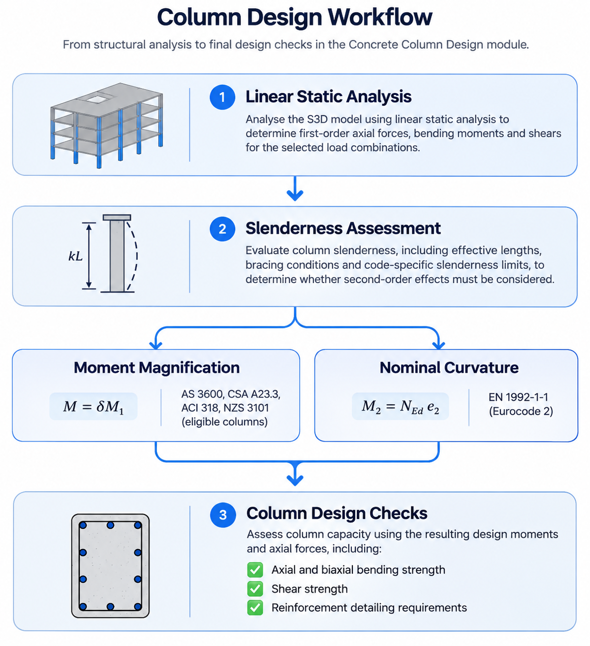
Design checks use linear static analysis and code-specific simplified slenderness methods, including sway moment magnification where supported. Geometrically nonlinear analysis is not performed. Strength and detailing checks are evaluated against all selected load combinations, with results available in individual column reports and a project-wide summary.
For detailed calculations and design checks, refer to the Quick Design documentation linked above.
Getting Started
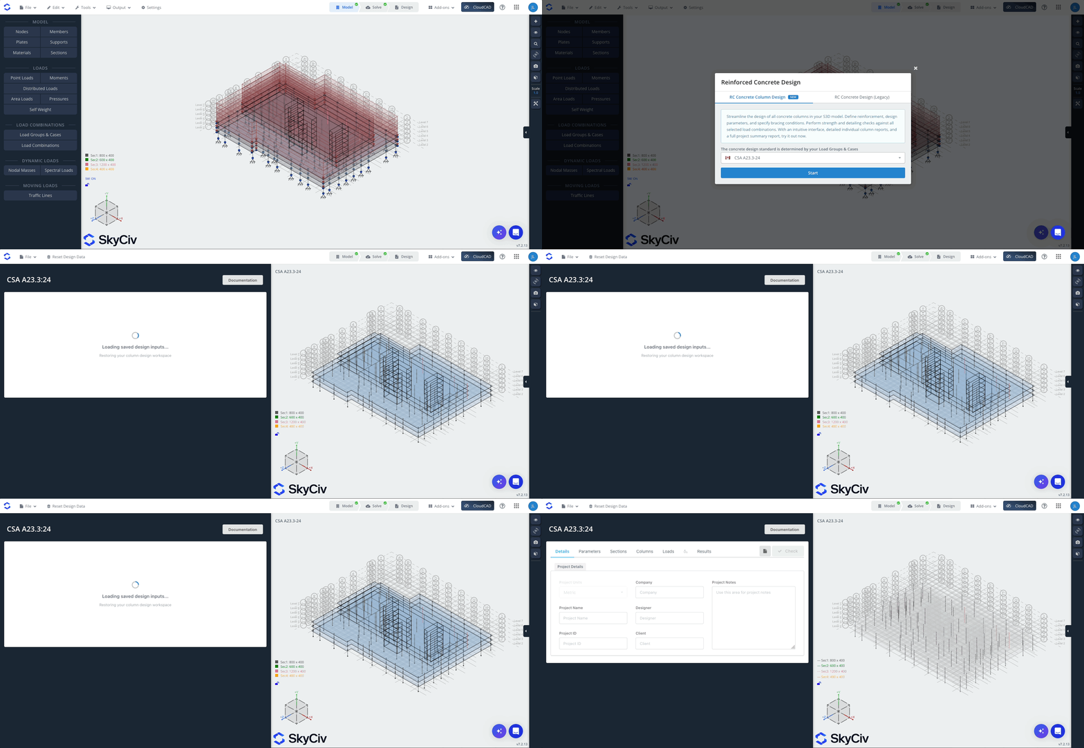
The module is organised into a series of tabs that guide you through the design process from left to right:
- Details – Enter project information, including the project name, company, designer, client, and notes.
- Parameters – Define default design parameters for all columns, including concrete cover, steel yield strength, concrete grade, effective length factors, and code-specific settings.
- Sections – Review and configure section-specific properties, including cover, steel yield strength, and concrete grade. Generate and preview longitudinal and shear reinforcement arrangements for each section.
- Columns – Review the concrete columns automatically identified in your S3D model. Assign reinforcement arrangements, effective length factors, and bracing conditions to individual columns.
- Loads – Select the load combinations from your S3D model to include in the design checks.
- δs (Sway Factor) – Define storeys and calculate sway moment magnification factors. This tab is available for AS 3600, CSA A23.3, and ACI 318. See Sway Columns and Storeys.
- Results – Review governing utilisation ratios, detailing checks, and design reports after running the design check.
Parameters
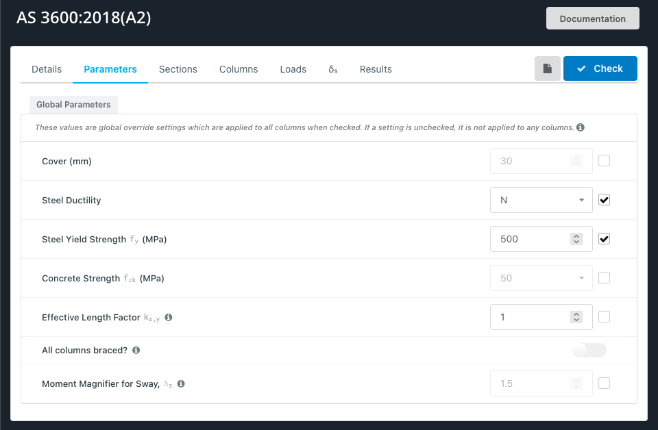
The Parameters tab defines the default design settings applied across the project. Each parameter includes an Override option. When enabled, the specified value takes precedence over any corresponding settings defined in the Sections or Columns tabs. When disabled, more specific section-level or column-level values will take precedence. Common design parameters include:
- Cover – Clear concrete cover to reinforcement.
- Steel Yield Strength and Concrete Grade – Default material properties applied where section-specific values have not been defined.
- Effective Length Factor (k) – Default effective length factors specified independently for each bending axis.
- Sway Directions – Define is all columns are braced in the structure.
Additional parameters are available for specific design standards:
- AS 3600 – Allows manual specification of the sway moment magnification factor (δs) instead of calculating it from the model.
- EN 1992-1-1 – Provides creep-related settings, including the option to specify a creep ratio directly or calculate it using loading age, relative humidity, cement class, and ambient temperature.
Sections and Reinforcement
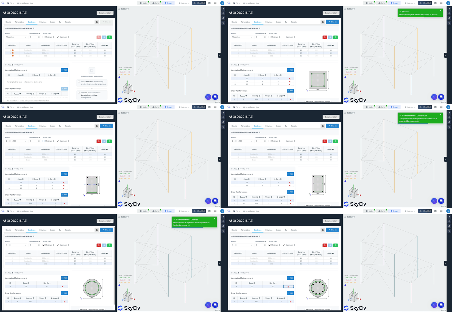
The Sections tab displays each section associated with the selected concrete columns. For each section, you can review or modify the concrete cover, steel yield strength, and concrete grade, as well as generate and preview the available longitudinal and shear reinforcement arrangements. Reinforcement can then be assigned to individual columns through the Columns tab using one of two approaches:
- Assigned Reinforcement – Select a specific reinforcement arrangement for a column. Only the selected arrangement will be evaluated during the design check.
- Unassigned Reinforcement (Optimisation) – Leave the reinforcement unassigned to evaluate all generated arrangements for the corresponding section. The module will identify and report the optimal arrangement.
Sway Columns and Storeys
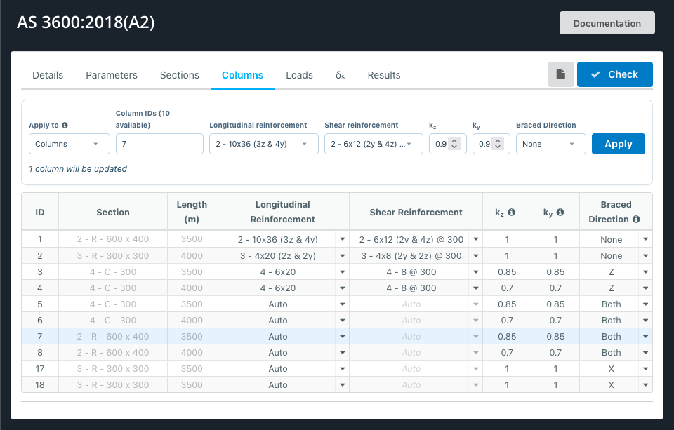
Columns can be classified as braced or unbraced (sway) independently for each bending direction through the Columns tab. These classifications are user-defined design assumptions and do not need to correspond directly to the support conditions specified in the structural analysis model. For AS 3600, CSA A23.3, and ACI 318, sway moment magnification factors (δs) can be calculated using the model geometry and applied loads. To perform this calculation, columns must first be assigned to storeys. The calculation considers the combined axial loads and critical buckling loads of the unbraced columns within each storey. Use the δs tab to:
- Assign Storeys – Group columns into storeys based on their elevations.
- Calculate Sway Factors – Run the δs calculation for the selected load combinations.
- Review Results – View the calculated δs factors for each storey, load combination, and bending direction.
Once calculated, the sway factors are automatically retained and used in subsequent design checks and reports. Recalculation is only necessary when the structural model or design input changes or when you choose to run the calculation again.
Design Theory and Analysis Methodology
General Design Approach
The Concrete Column Design module uses a three-dimensional linear static analysis to obtain first-order member forces, moments and displacements for the selected load combinations. It then evaluates column slenderness and, where required and permitted by the selected design standard, incorporates second-order effects using simplified member design procedures.
First-Order and Second-Order Effects
A first-order linear static analysis calculates equilibrium using the original, undeformed geometry. It does not directly include additional moments caused by displacement under axial load. These second-order effects are commonly distinguished as:
- Local P-δ effects: Additional bending caused by curvature of an individual column between its ends.
- Global P-Δ effects: Additional bending caused by relative translation of column ends, including inter-storey drift.
Code-specific simplified design methods can approximate these effects without a full geometrically nonlinear analysis, provided their assumptions and applicability limits are satisfied. The distinction between local and global effects is important: a member slenderness calculation does not necessarily establish global structural stability.
Effective Length and Member Stiffness
The effective length factor reflects the influence of end restraint and sway behaviour on a column’s susceptibility to buckling. In moment magnification methods, the critical load generally takes the form:
Here, Pc is the critical buckling load, (EI)eff is the code-prescribed effective flexural stiffness, k is the effective length factor, and L is the unsupported length. The stiffness provisions may allow for cracking, reinforcement and sustained loading. Effective length factors are specified independently for the relevant bending directions.
Braced and Sway Design
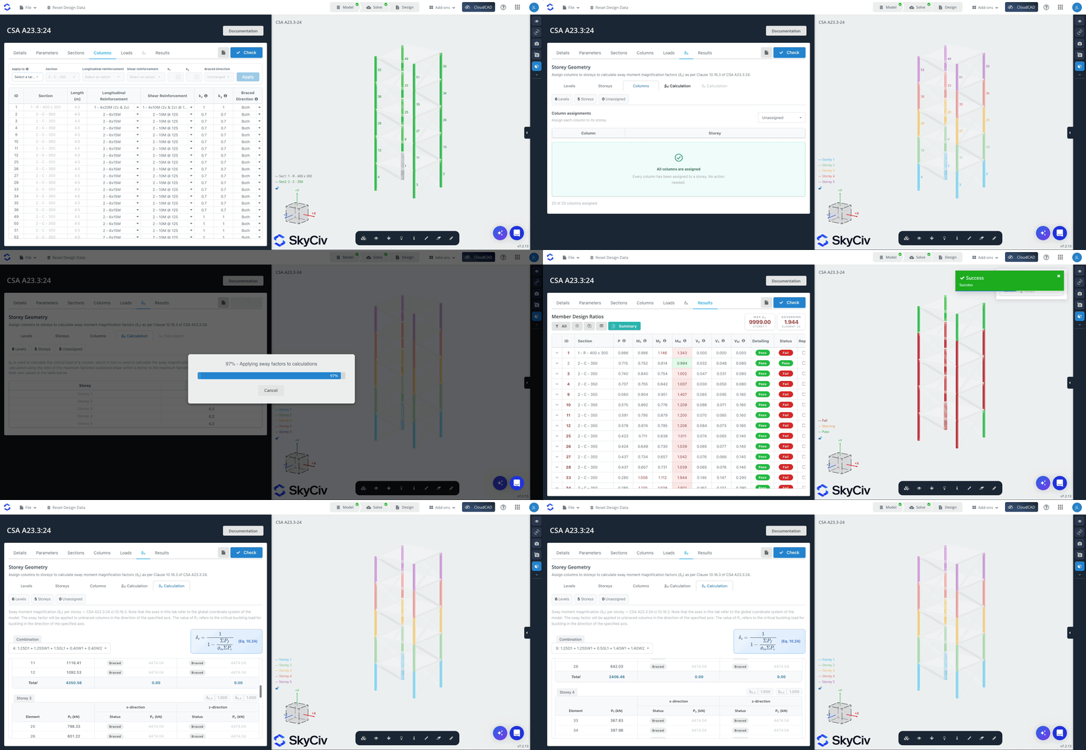
Braced (non-sway) columns are restrained against significant relative lateral translation of their ends. Their simplified design principally addresses local member curvature. Unbraced (sway) columns may also experience global displacement effects. For AS 3600, CSA A23.3 and ACI 318, the module calculates sway magnification factors using the storey-level axial loads and critical buckling loads of the sway-resisting columns. These factors are incorporated into the relevant code-specific design moments. Local member effects are checked separately where required. Braced and unbraced classifications are design assumptions supplied by the engineer. They must be consistent with the actual structural stability system, not merely the support symbols in the analytical model.
Design Standard Methods
AS 3600:2018 — Australia
Reference: Clause 10.4 — Design of Slender Columns.
Braced columns (Clause 10.4.2): The applicable first-order moment is magnified where required, using the design axial force, moment distribution, critical buckling load and code-prescribed effective stiffness and length.
Unbraced columns (Clause 10.4.3): The design accounts for sway effects through the applicable sway magnification provisions, as well as member slenderness. The module calculates storey sway factors using the combined axial loads and critical buckling loads of sway-resisting columns. The applicable design moment is then determined in accordance with the code. Limitations: The simplified procedures are valid only within the standard’s specified scope. Complex global instability or conditions outside that scope require a separate, suitable stability assessment.
NZS 3101.1:2006 — New Zealand
Reference: Clause 10.3.2 — Slenderness Effects in Columns.
Braced columns (Clause 10.3.2.3): Eligible columns may use the simplified moment magnification procedure. Applicability depends on the prescribed slenderness, relative displacement and plastic-region restrictions. Where slenderness effects cannot be neglected under Clause 10.3.2.3.4, moments are magnified under Clause 10.3.2.3.5 using the axial force, critical buckling load and moment distribution.
Unbraced columns (Not Supported): The simplified braced-column magnification method is not a general sway-frame procedure. Members outside its scope require an alternative method permitted by the standard, including second-order structural analysis where necessary. Limitations: First-order member design alone does not establish compliance for an unbraced column or a member ineligible for the simplified method.
EN 1992-1-1:2004 — Eurocode 2
Reference: Clause 5.8 — Analysis of Second-Order Effects with Axial Load. Eurocode 2 permits general nonlinear analysis (Clause 5.8.6), nominal stiffness (Clause 5.8.7) and nominal curvature (Clause 5.8.8). The module uses the nominal curvature method for individual column effects. Slenderness (Clause 5.8.3): The member slenderness is λ = l0 /i, where l0 is effective length and i is the radius of gyration of the uncracked concrete section. The code’s limiting slenderness determines whether member second-order effects may be neglected. Nominal curvature (Clause 5.8.8): Columns that are deemed to be slender must be designed for an additional moment, M2:
Global stability: The nominal curvature method principally addresses member-level effects. Global second-order effects must be shown to be negligible or accounted for separately under Clause 5.8; the simplified criterion in Clause 5.8.3.3 is available only where its conditions are met. Applicable National Annex provisions must also be considered.
CSA A23.3:24 — Canada
Reference: Clauses 10.13–10.16 — Slenderness Effects.
Non-sway columns (Clause 10.15): Member moments are magnified where required using the first-order moment distribution, axial force, effective length and prescribed effective stiffness.
Sway columns (Clause 10.16): The code combines first-order non-sway and magnified sway end-moment components:
The module uses the simplified critical-load-based sway magnification method of Clause 10.16.3.2:
Here, ΣPf represents total vertical loads in the storey and ΣPc the sum of critical buckling loads of sway-resisting columns. The critical loads are calculated using the code-prescribed effective lengths and stiffnesses. Limitations: The method requires appropriate separation of sway and non-sway moment components, suitable storey-level stability information, and additional local slenderness checks where applicable.
ACI 318-25 — United States
Reference: Section 6.6.4 — Slenderness Effects, Moment Magnification Method.
Non-sway columns (Section 6.6.4.5): The member moment magnification method uses the first-order moment distribution, axial force and critical buckling load. Its general expression is:
Here, Cm accounts for moment distribution, Pu is the factored axial force, and Pc is the critical buckling load. Minimum moment and other code requirements also apply.
Sway columns (Section 6.6.4.6): The design combines first-order non-sway and magnified sway moments:
The module uses the simplified critical-load-based sway magnification procedure:
Limitations: Simplified storey magnification is principally based on plane-frame behaviour.
Summary of Design Methods
| Design standard | Braced / non-sway | Unbraced / sway |
|---|---|---|
| AS 3600:2018 | Moment magnification — 10.4.2 | Sway magnification — 10.4.3 |
| NZS 3101.1:2006 | Eligible braced-column magnification — 10.3.2.3 | Alternative permitted analysis/design route |
| EN 1992-1-1:2004 | Nominal curvature — 5.8.8 | Member curvature; global stability separately verified |
| CSA A23.3:24 | Moment magnification — 10.15 | Sway magnification — 10.16 |
| ACI 318-25 | Moment magnification — 6.6.4.5 | Sway magnification — 6.6.4.6 |
Scope and Limitations
The module applies code-prescribed simplified slenderness methods following linear static analysis. It does not perform a general geometrically nonlinear analysis or independently verify every possible global instability mode. The engineer must ensure that:
- Bracing classifications, effective lengths and restraint conditions reflect the actual structural behaviour.
- Applicable member stiffness, creep and sustained-load assumptions are satisfied.
- Sway magnification uses the required storey loads, sway-resisting members and moment components.
- All code-specific limits and eligibility requirements are met.
- Significant torsional, irregular or otherwise complex global stability behaviour is evaluated by an appropriate additional method where necessary.
Where the simplified procedure is not permitted, an appropriate second-order analysis or another code-permitted design route is required.
Running the Design Check
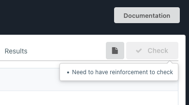
Click Check, located at the top-right of the tab navigation, to run the design checks for all selected columns and load combinations. Before the design check can proceed, the following requirements must be satisfied:
- Each selected column must have a valid reinforcement arrangement assigned or be explicitly left unassigned for reinforcement optimisation.
- Storey assignments must be complete where required for sway moment magnification calculations.
The Check button remains disabled until all applicable requirements are met. If the button is disabled, hover over it to view the outstanding requirements.
Reading Results
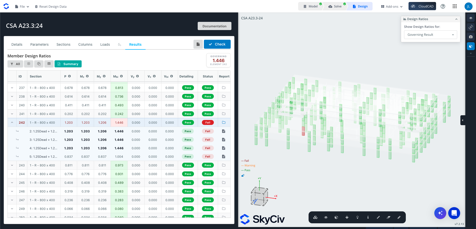
After completing a design check, the Results tab displays the design outcomes for each column and selected load combination. Results include:
- Axial Utilisation – Governing axial design ratio.
- Biaxial Bending Utilisation – Governing biaxial moment design ratio (selected design standards).
- Shear Utilisation (Vy/Vz) – Governing shear design ratios for each direction.
- Detailing Check – Pass/fail status for the applicable reinforcement detailing requirements.
- Overall Governing Ratio – The highest governing utilisation ratio, with the controlling element identified at the top of the results table.
Detailed reports are available at both the individual column and project levels:
- Individual Column Report – Select a column and load combination to view its detailed design calculations and results.
- Summary Report – Click Summary to generate and download a consolidated report covering the project.
The 3D model view also colour-codes columns according to their governing utilisation ratios, making it easy to identify columns approaching or exceeding their design capacity.
Design Log
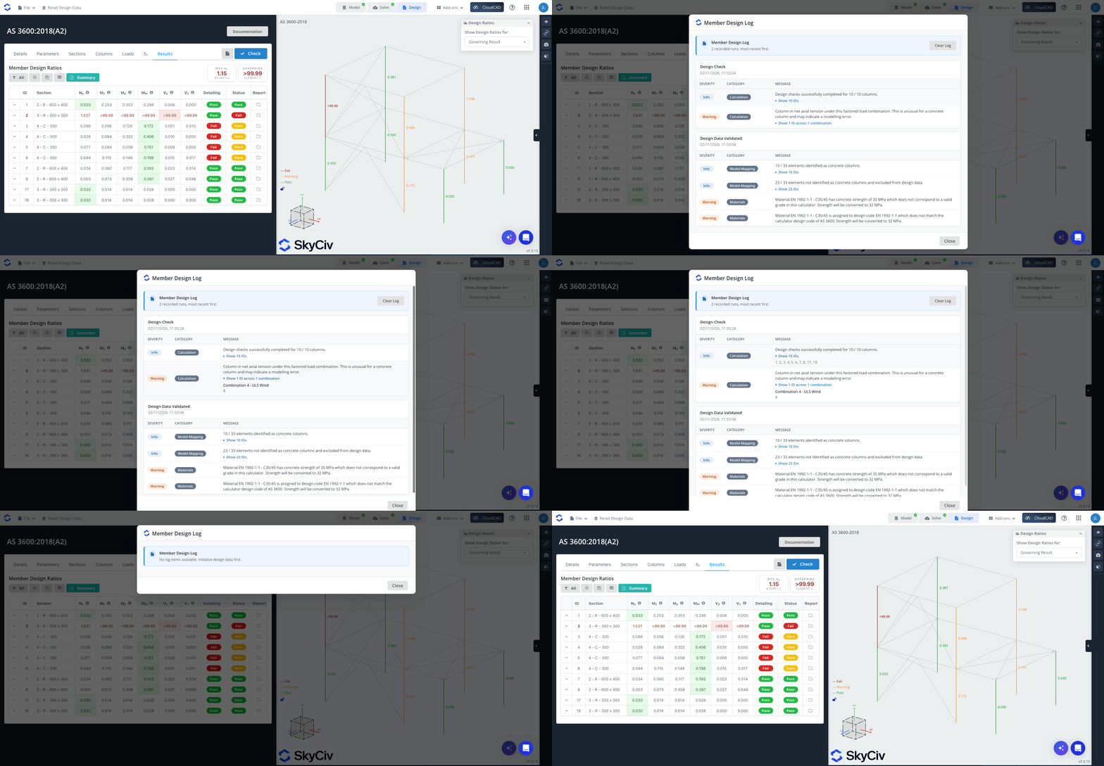
The Design Log button, located beside Check, opens the Member Design Log. This log maintains a history of warnings and errors recorded during recent design checks, helping you identify and resolve issues that may affect the results. Typical log entries include:
- Missing load cases or combinations.
- Input values outside permitted ranges that have been automatically adjusted.
- Columns excluded from a design check due to invalid or incomplete data.
The Design Log button is highlighted whenever the latest design run generates a new warning or error.
Change Log
- November 2026 – Initial release.
Feedback
We’re continually working to improve and expand our design tools. If you have suggestions, feature requests, or feedback, please submit them through Library → Calculator Info → Feedback

