
Overview
This calculator is for the design of reinforced non-prestressed concrete columns as per EN 1992-1-1:2004, Eurocode 2: Design of concrete structures. The following calculations are performed:
- Column slenderness is determined in each direction depending on user inputs.
- Design bending moments are calculated based on slenderness.
- Moment capacities are derived from interaction diagrams, which are drawn based on the section properties of the column.
- Shear capacities of the section are determined using the inclined strut truss model.
- Detailing checks are performed on the section.
Assumptions
General
Design Basis
- This tool has been created in alignment with the design principles set out in EN 1992-1-1:2004.
- The design equations for circular columns are supplemented by the research paper “Shear design of circular concrete sections using the Eurocode 2 truss model” by Orr et al.
‘Best Practice’
Users have the option of toggling whether ‘best practice’ values should be applied throughout the calculation or not. These values comprise the following:
- Single curvature bending – an additional term, M02 + M2, is added to the moment calculation for slender members if the column is bending in single curvature:
- Slenderness limit, λlim – absolute maximum value of 50 or:
- Biaxial Bending Utilisation of circular columns is taken as the square root of equation 5.39:
- Shear web width bw of circular columns is calculated using the equivalent rectangle as discussed in section ‘Calculation of bw’’.
- Biaxial Shear Utilisation is calculated as the resultant of the mono-axial shear utilisations in the ‘Y’ and ‘Z’ axes. EN1992-1-1:2004 does not provide specific guidance on how to consider a concrete section for biaxial shear, so this value is provided as a conservative safeguard:
- Maximum spacing of longitudinal bars set to 175mm, which assumes that the face of the column could be in tension. If best practice is not selected then the default value is 400mm, which assumes the section is in compression.
- Minimum number of longitudinal bars in a circular column = 6.
- Minimum bar spacing:
| Bar Diameter (mm) | Minimum Spacing (mm) |
|---|---|
| 12 | 40 |
| 16 | 45 |
| 20 | 50 |
| 25 | 55 |
| 32 | 70 |
| > 32 | 90 |
Section Analysis
Interaction Diagrams
The bending capacity of the concrete column is derived from interaction diagrams drawn for each axis. The interaction line is plotted by calculating values of ‘M’ and ‘N’ at varying depths of the neutral axis. This is done by determining the strains in the concrete and reinforcement bars for a given depth of the neutral axis. These strains can be converted into forces, which can then be used to calculate the maximum axial load and bending moment that the column can resist for that neutral axis depth.
- Moments are taken about the plastic centroid of the section.
- The concrete block strength η.fcd is reduced by 10% for circular sections as per 3.1.7(3).
- The resultant concrete force is assumed to act at the centroid of the rectangular stress block.
- For rectangular sections, this is taken as half the height of the block.
- For circular sections, this is calculated by finding the centroid of the segment in compression, where the height of the segment is equal to λ.X.
Column Design
Design Moments
The moments used to design a concrete column depend on the slenderness of the column in the considered axis. If the column is not slender (or ‘stocky’), then the column only needs to be checked for first order moments. The column must be designed for second order moments for each axis about which it is slender.
Users have the option to directly provide second-order moments to be used in the calculation. This option is only available if the column is slender.
The work flow for calculating second order moments based on the first order input is as follows:
Calculate Slenderness
Calculate Moment
Bending Capacity
The bending moment capacity is calculated in each axis by plotting the coordinates of the design forces (axial load and bending moment) on the interaction diagrams. A line is drawn parallel to the x-axis, which intersects this coordinate (N = design axial load). The moment capacity is taken at the point where this line intersects the interaction line.
Biaxial Bending Check
Shear Capacity
The applied shear force is initially checked against the shear capacity of the concrete only. If the resistance exceeds the applied shear, then the capacity of the section is taken as that of the concrete, VRd = VRd,c.
If the applied shear is greater than the capacity of the concrete, then the resistance of the section is taken as the minimum of the shear reinforcement capacity and the crushing strength of the inclined concrete strut, VRd = min[ VRd,max; VRd,s ].
The values for VRd,c, VRd,max and VRd,s are calculated using the equations set out in En 1992-1-1:2004 for rectangular sections. The equations for circular columns are taken from “Shear design of circular concrete sections using the Eurocode 2 truss model”.
For both shapes, the upper and lower bound value for the concrete strut capacity, (VRd,max) are determined for cotθ = 1 and cotθ = 2.5 respectively. If the applied shear force VEd is greater than the upper bound value, then cotθ = 2.5 is used to define the strut angle. If the shear force is less than the lower bound, cotθ = 1 is used. When VEd is between these two values, the design angle of θ is iteratively increased until VRd,max > VEd. This angle is used in the rest of the calculation.
Calculation of bw
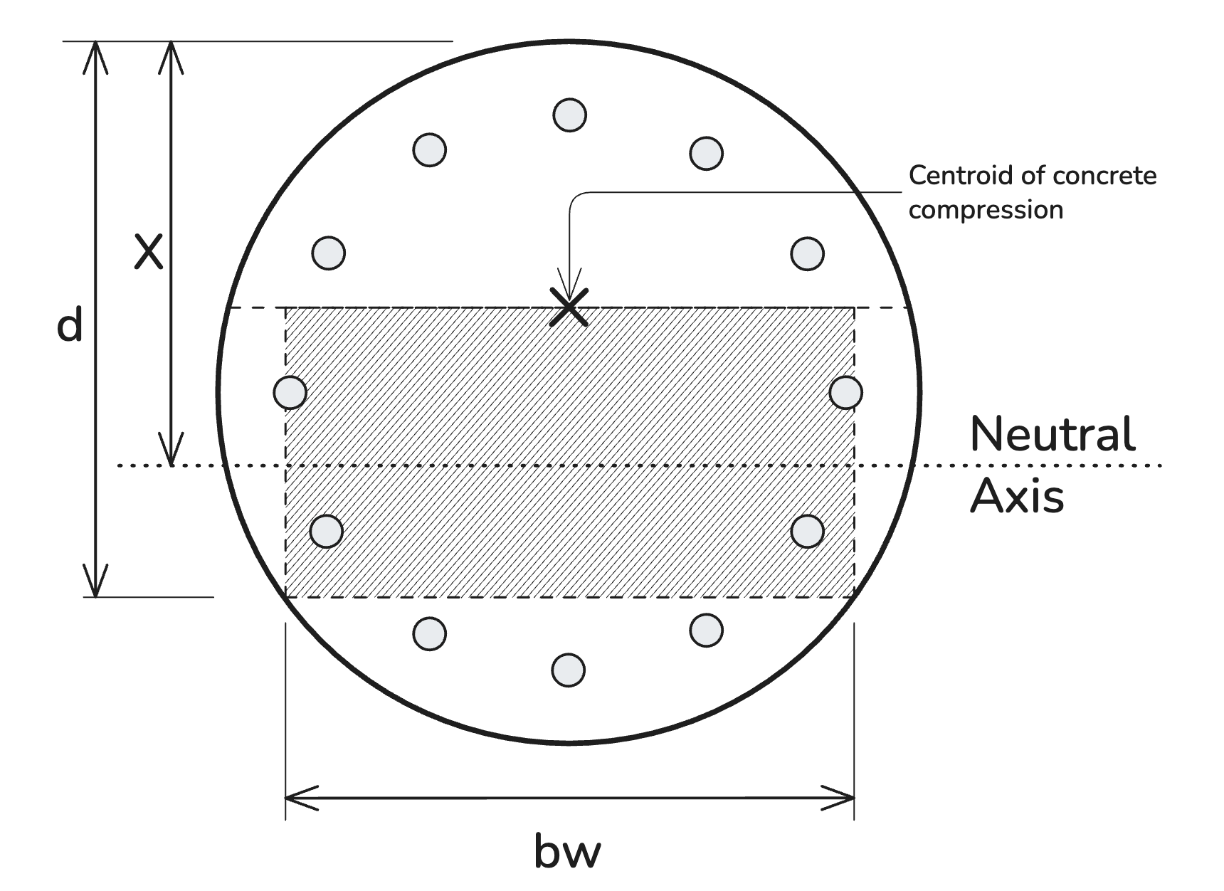
The section width for rectangular sections is taken as the perpendicular dimension to the direction of the applied shear force. For circular sections, when best practice is applied, an ‘equivalent rectangle’ is used to calculate the compression strut cross-section. The width of this rectangle ‘bw’ is taken as the smaller of the width of the circular section at the centroid of the compression chord and the width of the circular section at the centroid of tension reinforcement. If best practice is not applied, the shear web width is taken as the diameter of the circle.
Approximation of z
This calculator uses 0.9d as an approximation for the internal lever arm of the section when calculating the shear reinforcement capacity. This is a suggested value in EN 1992-1-1:2004 for members without axial load, and as such may not be accurate.
Concrete Strut Strength
This calculator allows for a column to be designed with an axial tension force. When calculating the concrete strut capacity in clause 6.2.3(3) (Eq 6.9), the value of fcd needs to be modified to suit tension conditions in the concrete strut. To do this, the concrete strength is calculated according to 6.5.2(2), using strength reduction factors of 0.6.v’ (6.57N).
Shear Capacity Of Rectangular Columns
Shear Capacity Of Circular Columns
Effects Of Creep
Users have several options for defining the effects of creep on the column they are designing.
If the column is non-slender, then default values may be used in the calculations. This will set the value of ‘A’ to 0.7 in Eq 5.13N for the slenderness limit.
There are no default values specified for the creep factor used to calculate curvature (Kφ) in EN 1992-1-1: 2004. If the column is determined to be slender, the user must input their own value or provide sufficient data to calculate the effective creep ratio φef.
Annex B of EN 1992-1-1:2004 is used to calculate φ(∞,t0). This calculator substitutes quasi-permanent moment for axial load, as this is deemed to be comparable and simpler to derive.
Fire Resistance
This is an optional check, enabled via the Fire Resistance Check option, per EN 1992-1-2, Annex C. The method uses the column geometry, reinforcement and fire design actions to determine the required minimum column dimension and reinforcement axis distance, and is performed independently about each column axis using the corresponding slenderness and eccentricity. Annex C does not define which side of a rectangular section is the column width, so b is conservatively taken as the minimum column dimension for both axes.
- Annex C Tables C.1 to C.9 are only tabulated for columns exposed on more than one side; there is no one-side exposure variant in the tabulated method, so this option is not offered for this check.
Fire Check Inputs
The following parameters are determined for the axis being checked:
- Fire resistance rating
- Column slenderness, λ
- Fire load level, n
- Fire load eccentricity, e
- Mechanical reinforcement ratio, ω
- Column width, b (minimum column dimension)
- Reinforcement axis distance, a
The fire load level is calculated as:
where fcd and fyd are the ordinary (ambient) design strengths of concrete and steel.
The fire load eccentricity is calculated from the first order fire design actions about the axis being checked, converted to millimetres:
The calculated eccentricity is used directly to select and interpolate between the Annex C tables (see “Selection of Annex C Tables” below). It is not reduced; eccentricities above the highest tabulated value are outside the scope of Annex C (see “Fire Check Criteria”).
The mechanical reinforcement ratio is calculated as:
The reinforcement axis distance is taken as the distance from the exposed concrete surface to the centre of the longitudinal reinforcement.
The column slenderness used for the fire check is taken as the ambient (normal temperature) slenderness for the axis being checked. Annex C notes that its notations, including slenderness, are as defined in Clause 5.3.3. Per B.3.1(5), the effective length in fire l0,fi may be taken as l0 as a safe simplification, so a separate fire-specific effective length is not calculated here.
Fire Check Criteria
This module only performs fire checks using the tabulated method in EN 1992-1-2 Annex C. For concrete columns outside this scope, use the separate Fire Resistance Design module.
Annex C(1) applies to columns in braced structures with a width up to 600 mm and slenderness up to λ = 80 under standard fire exposure. The tabulated method is not used, and the fire check is reported as failed, when:
- The column is not braced about both axes.
- Fire axial load NEd,fi ≤ 0.
- Slenderness λ > 80.
- Fire load level n > 0.7.
- Mechanical reinforcement ratio ω < 0.1 or ω > 1.0.
- Fire eccentricity e > ehigh = min(0.5b, 200 mm), the highest tabulated eccentricity (Tables C.3, C.6 and C.9).
- Values below the lowest tabulated slenderness, load level or eccentricity are conservatively taken as the lowest available table value. This is not conservative for the mechanical reinforcement ratio (a lower ω requires larger dimensions), so ω < 0.1 is outside the scope of the tables.
- Columns wider than 600 mm are not rejected: they exceed every tabulated minimum width, so the check is governed by the axis distance. Cells marked (1) in Annex C require a width greater than 600 mm and a particular assessment for buckling, so they are always reported as failed.
Selection of Annex C Tables
The required fire dimensions are obtained from Tables C.1 to C.9. The appropriate tables depend on the mechanical reinforcement ratio and fire eccentricity. The eccentricity limits used to select the surrounding tables depend on the column width:
Mechanical reinforcement ratio is considered using the tabulated values:
The eccentricity and mechanical reinforcement ratio therefore identify four surrounding tables from C.1 to C.9 for interpolation.
Annex C Reference Tables
Tables C.1 to C.9 below (click a table title to expand) are transcribed from EN 1992-1-2 Annex C and give the minimum column width bmin (mm) and reinforcement axis distance a (mm) required for a given standard fire resistance R (min), slenderness λ and fire load level n, for columns exposed on more than one side. Tables C.1 to C.3 apply to mechanical reinforcement ratio ω = 0.1, Tables C.4 to C.6 to ω = 0.5, and Tables C.7 to C.9 to ω = 1.0; within each group of three, the tables correspond to low, moderate and high first order moment (i.e. increasing fire load eccentricity), as described in “Selection of Annex C Tables” above. Where a cell offers two alternative bmin/a combinations, either combination is an acceptable requirement.
- * Normally, the cover required by EN 1992-1-1 for durability and bond will control the value of a instead of the tabulated value.
-
- Requires a width greater than 600 mm. Particular assessment for buckling is required; the calculator reports the fire check as failed if an interpolation passes through one of these entries (see “Special Buckling Assessment” below).
- Values are tabulated at λ = 30, 40, 50, 60, 70, 80 and n = 0.15, 0.3, 0.5, 0.7; the calculator linearly interpolates between tabulated values as described in “Interpolation of Table Requirements” below.
Interpolation of Table Requirements
The fire requirements are determined using linear interpolation through four parameters. Annex C(2) permits linear interpolation between the different column tables (ω and e); the calculator also interpolates within each table for slenderness and fire load level.
For each selected Annex C table:
- The surrounding slenderness values are identified from λ = 30, 40, 50, 60, 70 and 80.
- The surrounding fire load levels are identified from n = 0.15, 0.3, 0.5 and 0.7.
- The requirements are first interpolated for fire load level.
- The resulting values are then interpolated for slenderness.
This produces a set of requirements from each of the four surrounding Annex C tables.
The results are then:
- Interpolated between the lower and upper eccentricity tables.
- Interpolated between the lower and upper mechanical reinforcement ratios.
The final result gives the required minimum column dimension, bmin, and reinforcement axis distance, a.
- Where the table provides more than one acceptable combination, each combination is retained as an alternative requirement.
- When any of slenderness, load level, mechanical reinforcement ratio or eccentricity falls outside or between the tabulated values used above, the report adds a note under the fire resistance criteria stating which values are not tabulated and are linearly interpolated between the adjacent Annex C tabulated values, or which values fall outside the tabulated range and use the nearest tabulated value directly.
Special Buckling Assessment
Some Annex C table entries are identified by the special condition “(1)”. If an interpolation passes through one of these entries, the normal tabulated result is not used. The fire check is reported as failed and a special buckling assessment is required.
Change Log
Feedback
We’re constantly looking to expand and improve our product offering!
If you have any requests or feedback, please submit them by following Library → Calculator Info → Feedback.

