
Horizontal brace connection design to AISC 360 follows the brace force through three load paths. 第一, the brace bolts deliver the force into the gusset. Then the gusset passes it to the two members it connects to, here a girder and a beam, through bolted single angles. Each load path gets its own checks: 滑, 轴承, block shear and tension at the brace; 螺栓剪, 轴承, 块剪, shear and flexure at each single angle; and bending and buckling of the gusset itself.
此页面从头到尾都是一个真实的例子. A W18x50 beam and a W21x44 girder meet at a W14x90 column, 和一个 1/2 in gusset at the corner between them takes a 2L5x3-1/2×1/2 brace at 45°. The brace carries 52 kip in tension or compression (LRFD). The gusset is bolted to the web of each member through an L4x3x3/8 single angle. 设计符合AISC 360-16 和 AISC 手册第 15 版. 每个方程都用它的数字写出来, in the same order as the calc sheet that the SkyCiv连接设计 模块为此连接生成.
What is a horizontal brace connection?
A horizontal brace connection joins a diagonal brace in the plane of a floor or roof to the corner where two framing members meet. Horizontal bracing carries lateral load across a diaphragm that cannot do it alone, such as an open roof or a floor with large openings, and takes it to the vertical bracing. Because the brace lies flat in plan, the gusset is horizontal and is usually connected to the webs of the beams just below the top flange.
In this example the gusset sits in the corner between a W18x50 beam and a W21x44 girder at a W14x90 column. It is notched around the column, so it has two legs: one along the girder and one along the beam. Each leg is bolted to its member through a 单角连接. The brace is a pair of 5×3-1/2×1/2 angles with their short legs back to back. 两个都 5 in legs lie flat on the same face of the gusset, with one line of four bolts through each. The brace-to-gusset checks are close to those in a vertical bracing connection, but there is no Uniform Force Method here. The report resolves the brace force into its two components and sends each one to the member it runs along.
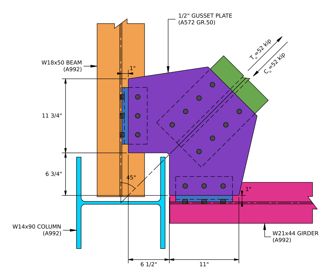
Plan view of the example connection. The gusset leg along the beam is 11 3/4 in long and the leg along the girder is 11 in long.
Horizontal brace connection design: 步骤一目了然
- 检查支撑螺栓处的细节限制.
- Check the slip resistance of the brace bolts.
- Check bolt bearing and tear-out on the gusset at the brace.
- 检查支架上的螺栓轴承和撕裂情况.
- Check block shear of the gusset at the brace.
- 检查支撑的块剪力.
- Check the gusset in tension on its Whitmore section.
- 检查带有剪力滞的拉伸断裂支撑.
- Check the detailing limits at the gusset side of the girder angle.
- Check the gusset-side bolt group of the girder angle in shear.
- Check bolt bearing on the girder angle, gusset side.
- Check bolt bearing on the gusset at the girder angle.
- Check the effective strength of the gusset-side bolts.
- Check block shear of the girder angle, gusset side.
- Check block shear of the gusset at the girder angle.
- Check the girder angle in shear.
- Check the gusset in shear along the girder angle.
- Check the girder angle in flexure, gusset side.
- Check shear and moment interaction of the girder angle, gusset side.
- Check the detailing limits at the girder.
- Check the bolt group to the girder by the instantaneous center of rotation.
- Check bolt bearing on the girder angle at the girder.
- 检查梁腹上的螺栓轴承.
- Check the effective strength of the bolts to the girder.
- Check block shear of the girder angle, girder side.
- Check the girder angle in shear, girder side.
- Check the girder angle in flexure, girder side.
- Check shear and moment interaction of the girder angle, girder side.
- Check the gusset in bending at the girder.
- Check the gusset in buckling at the girder.
- Repeat the bolt and angle checks at the beam.
- Check bolt bearing and block shear of the gusset at the beam angle.
- Check the gusset in shear along the beam angle.
- Check bolt bearing on the beam web.
- Check the gusset in bending at the beam.
- Check the gusset in buckling at the beam.
本示例的设计输入
设计代码为AISC 360-16 LRFD. 截面属性来自 AISC 手册.
| 物品 | 象征 | 值 |
|---|---|---|
| Brace force, 拉伸或压缩 | [mathin] T_{u,br},\ C_{u,br} [mathin] | 52 基普 |
| 柱 | AISC 连接设计示例, A992 | |
| 柱深 / 腹板厚度 | [mathin] d_{c},\ t_{w,c} [mathin] | 14 在 / 0.44 在 |
| 柱翼缘宽度 / 厚度 / 区域 | [mathin] b_{f,c},\ t_{f,c},\ A_{c} [mathin] | 14.5 在 / 0.71 在 / 26.5 英寸² |
| 梁 | W21x44, A992 | |
| 梁深度 / 腹板厚度 | [mathin] d_{g},\ t_{w,g} [mathin] | 20.7 在 / 0.35 在 |
| 梁翼缘宽度 / 厚度 / 区域 | [mathin] b_{f,g},\ t_{f,g},\ A_{g} [mathin] | 6.5 在 / 0.45 在 / 13 英寸² |
| 光束 | W18x50, A992 | |
| 波束深度 / 腹板厚度 | [mathin] d_{bm},\ t_{w,bm} [mathin] | 18 在 / 0.355 在 |
| 梁翼缘宽度 / 厚度 / 区域 | [mathin] b_{f,bm},\ t_{f,bm},\ A_{bm} [mathin] | 7.5 在 / 0.57 在 / 14.7 英寸² |
| Beam clearance | [mathin] clr [mathin] | 0 在 |
| 柱, girder and beam yield / 拉应力 | [mathin] F_{y},\ F_{u} [mathin] | 50 KSI / 65 KSI |
| 支撑 | 2L5x3-1/2×1/2-SLBB, A36 | |
| 支撑区 (both angles) | [mathin] A_{br} [mathin] | 8 英寸² |
| Brace leg on the gusset / leg off the gusset / 厚度 | [mathin] L_{on},\ L_{off},\ t_{br} [mathin] | 5 在 / 3.5 在 / 0.5 在 |
| Brace slope from the beam | [mathin] \theta_{br} [mathin] | 45° |
| 支撑无支撑长度 | [mathin] L_{b,br} [mathin] | 13 在 |
| 支撑产量 / 拉应力 | [mathin] F_{y,br},\ F_{u,br} [mathin] | 36 KSI / 58 KSI |
| 弹性模量 | [mathin] E [mathin] | 29000 KSI |
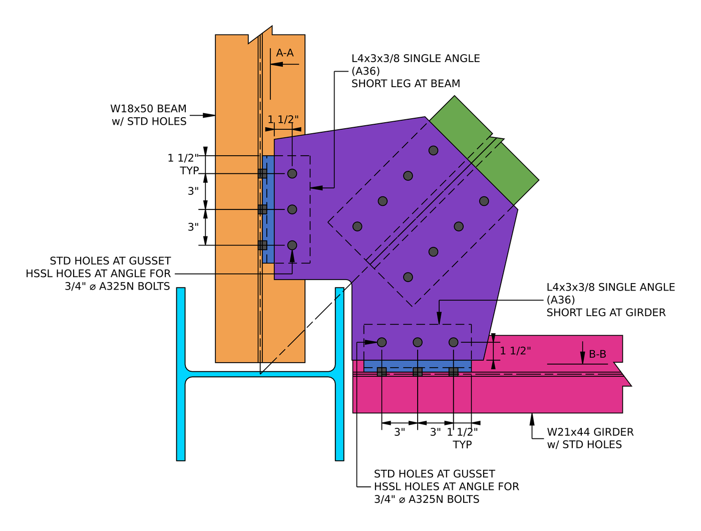
Single angle information. Each angle has its 4 in leg on the gusset and its 3 in leg on the member web, with three bolts at 3 in through each leg.
| 物品 | 象征 | 值 |
|---|---|---|
| 角撑板 | 1/2 在, A572级 50 | |
| 角板厚度 | [mathin] t_{gp} [mathin] | 0.5 在 |
| 角板产量 / 拉应力 | [mathin] F_{y,gp},\ F_{u,gp} [mathin] | 50 KSI / 65 KSI |
| Brace bolts | 3/4 in A325-SC, Class A surface | |
| Brace bolts: 行 / 间距 | [mathin] n_{r},\ s_{r} [mathin] | 4 / 3 在 |
| Brace bolts: 列 / gage between the bolt lines | [mathin] n_{c},\ g_{a} [mathin] | 2 / 6 在 |
| Brace bolts: end distance at the brace | [mathin] L_{ev} [mathin] | 1.5 在 |
| 支架上有孔 / 角撑板 | 标准 (性病) / 超大的 (OVS) | |
| 单角度 (两个都) | L4x3x3/8, A36, 9 in long | |
| Angle leg on the gusset | [mathin] L_{on,g} [mathin] | 4 在 |
| Gusset width / 长度 / offset at the girder | [mathin] b_{1},\ h_{1},\ o_{1} [mathin] | 6.75 在 / 11 在 / 1 在 |
| Gusset width / 长度 / offset at the beam | [mathin] b_{2},\ h_{2},\ o_{2} [mathin] | 6.5 在 / 11.75 在 / 1 在 |
| Angle bolts | 3/4 in A325N | |
| Angle bolts: 行 / 间距 / 列 | [mathin] n_{r},\ s_{r},\ n_{c} [mathin] | 3 / 3 在 / 1 |
| Gusset side: horizontal edge on the gusset / end distance on the angle | [mathin] L_{eh,gp},\ L_{ev} [mathin] | 1.5 在 / 1.5 在 |
| Gusset side: holes in the gusset / 角度 | 性病 / horizontal short slots (高速SSL) | |
| Member side: angle gage / end distance | [mathin] g_{a,to,sup},\ L_{ev} [mathin] | 1.75 在 / 1.5 在 |
| Member side: holes in the member web / 角度 | 性病 / 性病 |
The A36 grade on the brace angles and the single angles is normal for those parts. The gusset has oversized holes at the brace, so those bolts must be slip critical (AISC 360-16 J3.2). The single angles have short slots on the gusset leg, perpendicular to the load, which J3.2 allows in a bearing-type joint, so the angle bolts are A325N.
步 1: 支撑螺栓处的详细限制 (AISC 360-16 J3.3, J3.4, J3.5)
The bolt layout has to be buildable and has to match the assumptions behind the strength equations. Bolts that are too close tear out between the holes, and bolts too close to an edge tear out to the edge.
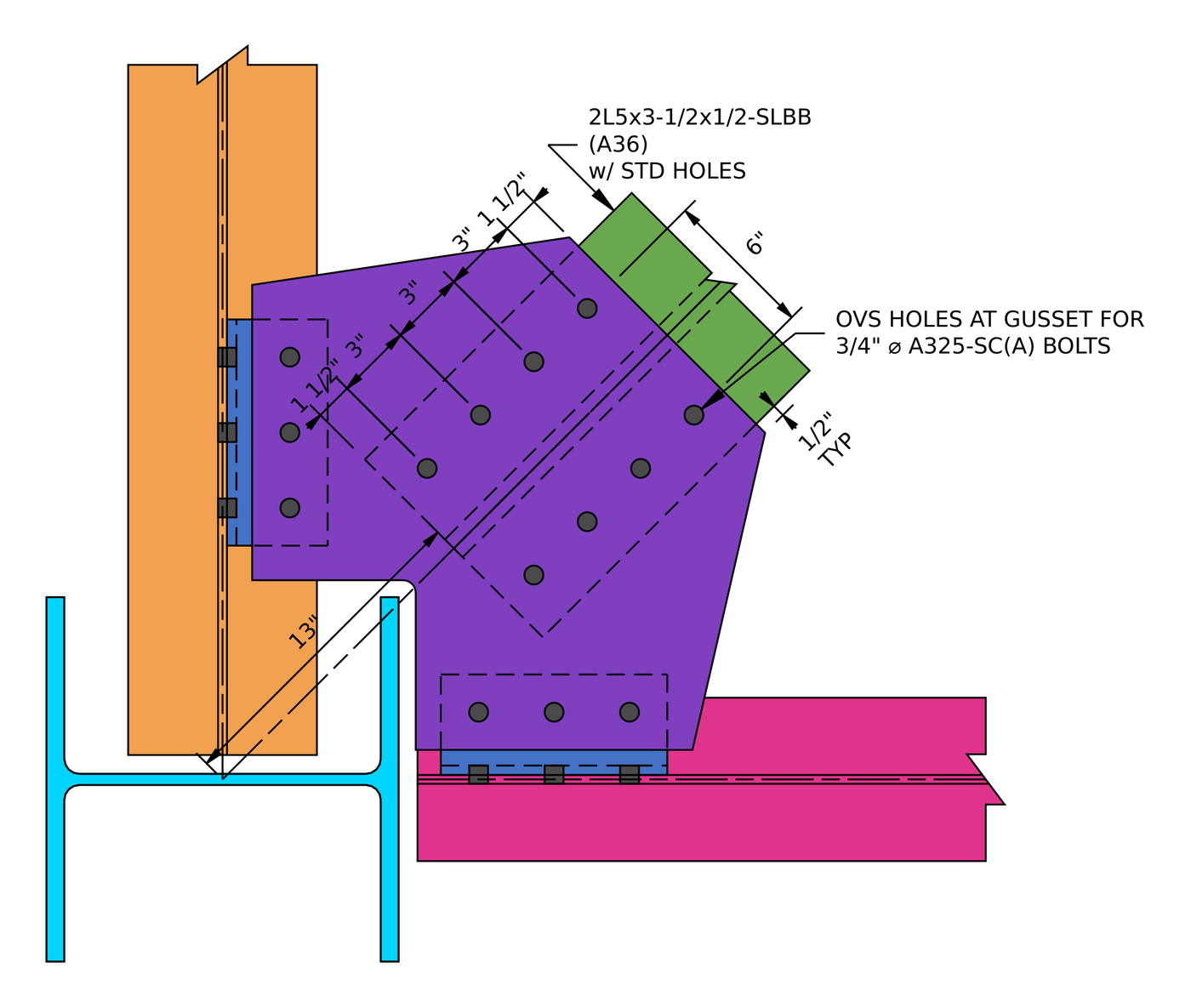
支撑连接细节. Two lines of four bolts at 3 在, one line through each angle, 与一个 6 in gage between them.
为一个 3/4 螺栓中的最小间距为 [mathin] 2\tfrac{2}{3} d_{b} = 2\,in [mathin] (J3.3) 最小边距为 1 在 (表J3.4). 角板上有超大孔, 因此表 J3.5 的增量为 1/16 in 将其最小结束距离提高到 1.063 在.
| 详细限制 | 限制 (在) | 实际的 (在) | 直流电 | 结果 |
|---|---|---|---|---|
| 最小螺栓规格 | 3.375 | 6.000 | 0.563 | 通过 |
| 最小螺栓排间距 | 2.000 | 3.000 | 0.667 | 通过 |
| 最大螺栓排间距 | 6.000 | 3.000 | 0.500 | 通过 |
| 最小螺栓柱间距 | 2.000 | 3.000 | 0.667 | 通过 |
| 最大螺栓柱间距 | 6.000 | 3.000 | 0.500 | 通过 |
| Gusset minimum vertical edge distance (OVS) | 1.063 | 1.500 | 0.709 | 通过 |
| 支撑最小垂直边缘距离 | 1.000 | 1.500 | 0.667 | 通过 |
| 支撑最小水平边缘距离 | 1.000 | 2.000 | 0.500 | 通过 |
控制行是角撑板端部距离及其超大孔增量:
[math] DCR = \frac{d}{c} = \frac{(1.063)}{(1.5)} = 0.70867 [math]
DCR = 0.709 < 1.0, 行
步 2: Slip resistance of the brace bolts (AISC 360-16 J3.8)
角板上有超大孔, 哪个 AISC 360-16 J3.2 只允许用于滑动关键的接头. The bolts are pretensioned, and friction between the brace angles and the gusset carries the brace force. 检查接头在分解载荷下是否不会滑动.
在哪里 [mathin] \phi = 0.85 [mathin] 用于超大孔, [mathin] \mu = 0.3 [mathin] for a Class A surface, [mathin] D_{u} = 1.13 [mathin], [mathin] h_{f} = 1 [mathin] 因为没有填充物, [mathin] T_{b} = 28\,kip [mathin] 对于一个 3/4 in A325 bolt (表J3.1), [mathin] N_{s} = 1 [mathin], [mathin] n_{r} = 4 [mathin] 和 [mathin] n_{c} = 2 [mathin]:
[math] \phi R_{n} = \phi\, \mu\, D_{u}\, h_{f}\, T_{b}\, N_{s}\, n_{r}\, n_{c} [math]
[math] \phi R_{n} = (0.85) \times (0.3) \times (1.13) \times (1) \times (28\,kip) \times (1) \times (4) \times (2) [math]
[math] \phi R_{n} = 64.546\,kip [math]
DCR = 52 基普 / 64.546 基普= 0.806 < 1.0, 行
There is one slip plane, not two, because both brace angles lie on the same face of the gusset. Each bolt clamps one angle leg to the gusset. That makes slip the governing check at the brace.
步 3: Bolt bearing and tear-out on the gusset at the brace (AISC 360-16 J3.10)
仍然需要检查滑动关键螺栓的轴承情况, because if the joint does slip, the bolts bear on the sides of their holes. The bolt nearest the end of the gusset has the least material in front of it.
角板孔过大, [mathin] d_{h} = 0.9375\,in [mathin]. Clear distances for the end bolt and between bolts:
[math] l_{c1} = L_{ev} – \frac{d_{h}}{2} = (1.5\,in) – \frac{(0.9375\,in)}{2} = 1.0313\,in [math]
[math] l_{c2} = s_{r} – d_{h} = (3\,in) – (0.9375\,in) = 2.0625\,in [math]
在哪里 [mathin] t_{gp} = 0.5\,in [mathin], [mathin] F_{u,gp} = 65\,ksi [mathin], [mathin] n_{r} = 4 [mathin], [mathin] n_{c} = 2 [mathin], [mathin] d_{b} = 0.75\,in [mathin] 和 [mathin] \phi = 0.75 [mathin]:
[math] \phi R_{n} = \phi \left[ \min\left(1.2\, l_{c1},\, 2.4\, d_{b}\right) t_{gp} F_{u,gp}\, n_{c} + \min\left(1.2\, l_{c2},\, 2.4\, d_{b}\right) t_{gp} F_{u,gp}\, n_{c} \left( n_{r} – 1 \right) \right] [math]
[math] \phi R_{n} = (0.75) \times \left[ \min\left(1.2 \times (1.0313\,in),\, 2.4 \times (0.75\,in)\right) \times (0.5\,in) \times (65\,ksi) \times (2) + \min\left(1.2 \times (2.0625\,in),\, 2.4 \times (0.75\,in)\right) \times (0.5\,in) \times (65\,ksi) \times (2) \times ((4) – 1) \right] [math]
[math] \phi R_{n} = 323.58\,kip [math]
DCR = 52 基普 / 323.58 基普= 0.161 < 1.0, 行
Tear-out governs the end bolts. The inner bolts reach the bearing cap of 2.4 db.
步 4: 支架上的螺栓轴承和撕裂 (AISC 360-16 J3.10)
The same check applies to the brace angles. Each bolt passes through one angle leg, so the bearing thickness is a single leg, [mathin] t_{br} = 0.5\,in [mathin].
The angles have standard holes, [mathin] d_{h} = 0.8125\,in [mathin]:
[math] l_{c1} = (1.5\,in) – \frac{(0.8125\,in)}{2} = 1.0938\,in \qquad l_{c2} = (3\,in) – (0.8125\,in) = 2.1875\,in [math]
和 [mathin] F_{u,br} = 58\,ksi [mathin]:
[math] \phi R_{n} = \phi \left[ \min\left(1.2\, l_{c1},\, 2.4\, d_{b}\right) t_{br} F_{u,br}\, n_{c} + \min\left(1.2\, l_{c2},\, 2.4\, d_{b}\right) t_{br} F_{u,br}\, n_{c} \left( n_{r} – 1 \right) \right] [math]
[math] \phi R_{n} = (0.75) \times \left[ \min\left(1.2 \times (1.0938\,in),\, 2.4 \times (0.75\,in)\right) \times (0.5\,in) \times (58\,ksi) \times (2) + \min\left(1.2 \times (2.1875\,in),\, 2.4 \times (0.75\,in)\right) \times (0.5\,in) \times (58\,ksi) \times (2) \times ((4) – 1) \right] [math]
[math] \phi R_{n} = 292\,kip [math]
DCR = 52 基普 / 292 基普= 0.178 < 1.0, 行
步 5: Block shear of the gusset at the brace (AISC 360-16 J4.3)
螺栓周围的一块角撑板可能会撕裂: shear along the bolt lines plus tension across the end. The report checks two shapes. The L pattern tears along one bolt line and across to the gusset edge. The U pattern tears along both bolt lines and across between them.
的 1/16 in added to each hole is the B4.3 allowance for damage when the hole is punched. 和 [mathin] d_{h} = 0.9375\,in [mathin], [mathin] s_{c} = 3\,in [mathin], [mathin] g_{a} = 6\,in [mathin], [mathin] L_{eh,gp} = 2\,in [mathin] 和 [mathin] L_{br,gp} = 12\,in [mathin], the brace length on the gusset. For the L pattern:
[math] A_{nt} = t_{gp} \left[ (n_{c} – 2)\, s_{c} + g_{a} + L_{eh,gp} – (n_{c} – 0.5)\left( d_{h} + 0.0625\,in \right) \right] = (0.5\,in) \times \left[ ((2) – 2) \times (3\,in) + (6\,in) + (2\,in) – ((2) – 0.5) \times ((0.9375\,in) + (0.0625\,in)) \right] = 3.25\,in^{2} [math]
[math] A_{gv} = t_{gp} \left[ L_{ev} + (n_{r} – 1)\, s_{r} \right] = (0.5\,in) \times \left[ (1.5\,in) + ((4) – 1) \times (3\,in) \right] = 5.25\,in^{2} [math]
[math] A_{nv} = t_{gp} \left[ L_{br,gp} – L_{ev} – (n_{r} – 0.5)\left( d_{h} + 0.0625\,in \right) \right] = (0.5\,in) \times \left[ (12\,in) – (1.5\,in) – ((4) – 0.5) \times ((0.9375\,in) + (0.0625\,in)) \right] = 3.5\,in^{2} [math]
[math] \phi R_{n} = \phi \left( 0.6\, F_{u,gp} A_{nv} + U_{bs} F_{u,gp} A_{nt} \right) \le \phi \left( 0.6\, F_{y,gp} A_{gv} + U_{bs} F_{u,gp} A_{nt} \right) [math]
[math] \phi R_{n} = (0.75) \times \left( 0.6 \times (65\,ksi) \times (3.5\,in^{2}) + (1) \times (65\,ksi) \times (3.25\,in^{2}) \le 0.6 \times (50\,ksi) \times (5.25\,in^{2}) + (1) \times (65\,ksi) \times (3.25\,in^{2}) \right) = 260.81\,kip [math]
For the U pattern:
[math] A_{nt} = t_{gp} \left[ (n_{c} – 2)\, s_{c} + g_{a} – (n_{c} – 1)\left( d_{h} + 0.0625\,in \right) \right] = (0.5\,in) \times \left[ ((2) – 2) \times (3\,in) + (6\,in) – ((2) – 1) \times ((0.9375\,in) + (0.0625\,in)) \right] = 2.5\,in^{2} [math]
[math] A_{gv} = 2\, t_{gp} \left[ L_{ev} + (n_{r} – 1)\, s_{r} \right] = 2 \times (0.5\,in) \times \left[ (1.5\,in) + ((4) – 1) \times (3\,in) \right] = 10.5\,in^{2} [math]
[math] A_{nv} = 2\, t_{gp} \left[ (n_{r} – 1)\, s_{r} + L_{ev} – (n_{r} – 0.5)\left( d_{h} + 0.0625\,in \right) \right] = 2 \times (0.5\,in) \times \left[ ((4) – 1) \times (3\,in) + (1.5\,in) – ((4) – 0.5) \times ((0.9375\,in) + (0.0625\,in)) \right] = 7\,in^{2} [math]
[math] \phi R_{n} = (0.75) \times \left( 0.6 \times (65\,ksi) \times (7\,in^{2}) + (1) \times (65\,ksi) \times (2.5\,in^{2}) \le 0.6 \times (50\,ksi) \times (10.5\,in^{2}) + (1) \times (65\,ksi) \times (2.5\,in^{2}) \right) = 326.63\,kip [math]
The governing pattern is the lower one:
[math] \phi R_{n} = \min\left( (260.81\,kip),\, (326.63\,kip) \right) = 260.81\,kip [math]
DCR = 52 基普 / 260.81 基普= 0.199 < 1.0, 行
步 6: 支撑块剪切 (AISC 360-16 J4.3)
Each brace angle can tear out its own block: shear along its bolt line and tension across to the toe of the leg. Each angle has one bolt line, which is why the equation uses half the bolt columns, [mathin] n_{c}/2 = 1 [mathin], and doubles the thickness to cover both angles.
和 [mathin] d_{h} = 0.8125\,in [mathin] 和 [mathin] L_{eh,br} = 2\,in [mathin]:
[math] A_{nt} = 2 t_{br} \left[ \left( \frac{n_{c}}{2} – 1 \right) s_{c} + L_{eh,br} – \left( \frac{n_{c}}{2} – 0.5 \right)\left( d_{h} + 0.0625\,in \right) \right] = (1\,in) \times \left[ ((1) – 1) \times (3\,in) + (2\,in) – ((1) – 0.5) \times ((0.8125\,in) + (0.0625\,in)) \right] = 1.5625\,in^{2} [math]
[math] A_{gv} = 2 t_{br} \left[ L_{ev} + (n_{r} – 1)\, s_{r} \right] = (1\,in) \times \left[ (1.5\,in) + ((4) – 1) \times (3\,in) \right] = 10.5\,in^{2} [math]
[math] A_{nv} = 2 t_{br} \left[ L_{br,gp} – L_{ev} – (n_{r} – 0.5)\left( d_{h} + 0.0625\,in \right) \right] = (1\,in) \times \left[ (12\,in) – (1.5\,in) – ((4) – 0.5) \times ((0.8125\,in) + (0.0625\,in)) \right] = 7.4375\,in^{2} [math]
[math] \phi R_{n} = (0.75) \times \left( 0.6 \times (58\,ksi) \times (7.4375\,in^{2}) + (1) \times (58\,ksi) \times (1.5625\,in^{2}) \le 0.6 \times (36\,ksi) \times (10.5\,in^{2}) + (1) \times (58\,ksi) \times (1.5625\,in^{2}) \right) = 238.07\,kip [math]
DCR = 52 基普 / 238.07 基普= 0.218 < 1.0, 行
步 7: Gusset tension on the Whitmore section (AISC 360-16 J4.1, AISC Manual Fig. 9-1)
The brace force spreads out from the bolts into the gusset at about 30° on each side. The Whitmore section is the width that this spread reaches at the last bolt row, and the gusset must yield and rupture on that width before anything else.
The bolt group length is [mathin] L_{br} = (n_{r} – 1)\, s_{r} = 9\,in [mathin] and the width between the outer bolt lines is [mathin] W_{br} = 6\,in [mathin]:
[math] W = 2\, L_{br} \tan(\theta) + W_{br} = 2 \times (9\,in) \times \tan(30) + (6\,in) = 16.392\,in [math]
张力屈服, 与 [mathin] \phi = 0.9 [mathin]:
[math] \phi R_{n,ty} = \phi\, F_{y,gp}\, t_{gp}\, W = (0.9) \times (50\,ksi) \times (0.5\,in) \times (16.392\,in) = 368.83\,kip [math]
Tension rupture through the two holes in the last row, 与 [mathin] \phi = 0.75 [mathin]:
[math] \phi R_{n,tr} = \phi\, F_{u,gp}\, t_{gp} \left[ W – n_{c}\left( d_{h} + 0.0625\,in \right) \right] = (0.75) \times (65\,ksi) \times (0.5\,in) \times \left[ (16.392\,in) – (2) \times ((0.9375\,in) + (0.0625\,in)) \right] = 350.81\,kip [math]
[math] \phi R_{n} = \min\left( (368.83\,kip),\, (350.81\,kip) \right) = 350.81\,kip [math]
DCR = 52 基普 / 350.81 基普= 0.148 < 1.0, 行
步 8: Brace tension rupture with shear lag (AISC 360-16 D3, J4.1)
Only one leg of each brace angle is bolted, so the stress has to flow from the outstanding leg into the connected leg. Shear lag reduces the effective net area by the factor U.
和 [mathin] \bar{y} = 1.65\,in [mathin], the brace centroid distance, and the connection length [mathin] (n_{r} – 1)\, s_{r} [mathin] (表 D3.1 案例 2):
[math] U = 1 – \frac{\bar{y}}{(n_{r} – 1)\, s_{r}} = 1 – \frac{(1.65\,in)}{((4) – 1) \times (3\,in)} = 0.81674 [math]
[math] \phi R_{n,tr} = \phi\, F_{u,br}\, U \left[ A_{br} – n_{c}\left( d_{h} + 0.0625\,in \right) t_{br} \right] = (0.75) \times (58\,ksi) \times (0.81674) \times \left[ (8\,in^{2}) – (2) \times ((0.8125\,in) + (0.0625\,in)) \times (0.5\,in) \right] = 253.14\,kip [math]
DCR = 52 基普 / 253.14 基普= 0.205 < 1.0, 行
在支架一侧, slip governs at 0.806 and every strength check is under 0.22.
步 9: Detailing limits at the gusset side of the girder angle (AISC 360-16 J3.3, J3.4, J3.5)
The report resolves the brace force into a component along the girder and a component along the beam. The gusset leg at the girder carries the component along the girder, which loads the single angle in shear along its length:
[math] V = P_{u,br} \sin(\theta_{br}) = (52\,kip) \times \sin((45)) = 36.77\,kip [math]
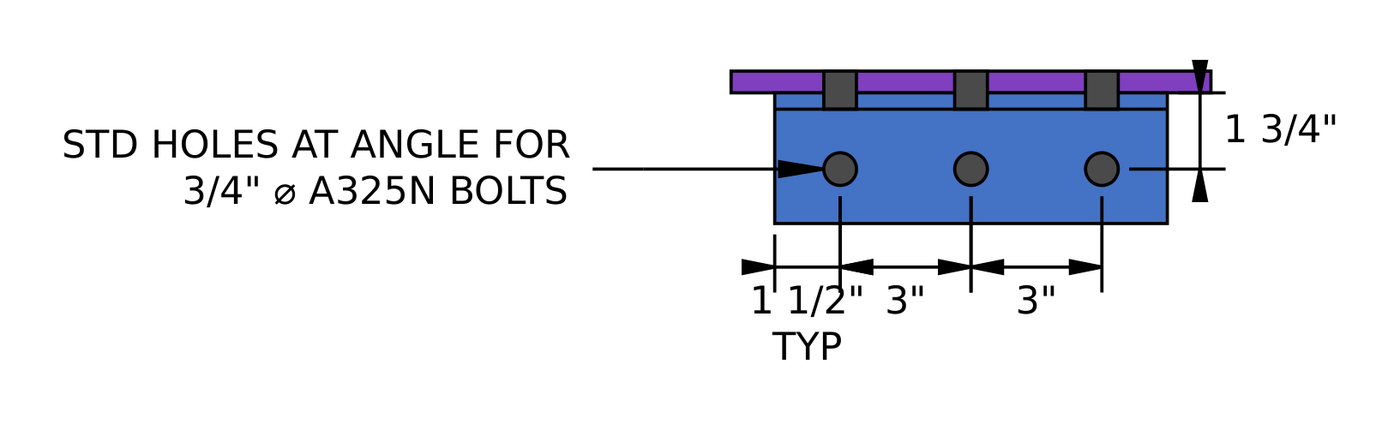
Section B-B at the girder. The angle’s 4 in leg is bolted to the gusset, and its 3 in leg is bolted to the girder web on a 1 3/4 在规格中.
| 详细限制 | 限制 (在) | 实际的 (在) | 直流电 | 结果 |
|---|---|---|---|---|
| 最小螺栓排间距 | 2.000 | 3.000 | 0.667 | 通过 |
| 最大螺栓排间距 | 6.000 | 3.000 | 0.500 | 通过 |
| Single angle minimum vertical edge distance | 1.000 | 1.500 | 0.667 | 通过 |
| Single angle minimum horizontal edge distance (高速SSL) | 1.125 | 1.500 | 0.750 | 通过 |
| Gusset minimum vertical edge distance | 1.000 | 2.500 | 0.400 | 通过 |
| Gusset minimum horizontal edge distance | 1.000 | 1.500 | 0.667 | 通过 |
| Minimum single angle length | 5.500 | 9.000 | 0.611 | 通过 |
| Minimum bolt gage for the single angle | 1.500 | 2.500 | 0.600 | 通过 |
The horizontal edge distance on the angle gets the Table J3.5 increment of 1/8 in for a short slot, 这给出了 1.125 在. The minimum angle length of 5.5 in is half the gusset length along the girder, [mathin] h_{1}/2 [mathin].
[math] DCR = \frac{d}{c} = \frac{(1.125)}{(1.5)} = 0.75 [math]
DCR = 0.750 < 1.0, 行
步 10: Gusset-side bolt group of the girder angle in shear (AISC 360-16 J3.6, AISC Manual p. 10-116)
The three bolts through the gusset leg of the angle carry V in single shear. For a single vertical row of bolts with an eccentricity of 3 in or less, the Manual lets you neglect the eccentricity, so the group coefficient is the bolt count, [mathin] C = 3 [mathin].
在哪里 [mathin] F_{nv} = 54\,ksi [mathin] for an A325N bolt, [mathin] d_{b} = 0.75\,in [mathin], [mathin] N_{s} = 1 [mathin], [mathin] h_{f} = 1 [mathin] 和 [mathin] \phi = 0.75 [mathin]:
[math] \phi R_{n} = \phi\, F_{nv}\, \frac{\pi}{4} d_{b}^{2}\, N_{s}\, C\, h_{f} = (0.75) \times (54\,ksi) \times \frac{\pi}{4} \times ((0.75\,in))^{2} \times (1) \times (3) \times (1) = 53.677\,kip [math]
DCR = 36.77 基普 / 53.677 基普= 0.685 < 1.0, 行
步 11: Bolt bearing on the girder angle, gusset side (AISC 360-16 J3.10)
Each bolt bears on its hole in the angle. The angle hole is a horizontal short slot, but the load runs along the angle, across the slot, so the hole dimension in the direction of the load is the slot width, [mathin] d_{h} = 0.8125\,in [mathin].
[math] l_{c1} = (1.5\,in) – \frac{(0.8125\,in)}{2} = 1.0938\,in \qquad l_{c2} = (3\,in) – (0.8125\,in) = 2.1875\,in [math]
和 [mathin] t_{L,gir} = 0.375\,in [mathin], [mathin] F_{u,L,gir} = 58\,ksi [mathin] and the group scaled by [mathin] C/n_{r} [mathin]:
[math] \phi R_{n} = \phi \left[ \min\left(1.2\, l_{c1},\, 2.4\, d_{b}\right) t_{L,gir} F_{u,L,gir} + \min\left(1.2\, l_{c2},\, 2.4\, d_{b}\right) t_{L,gir} F_{u,L,gir} \left( n_{r} – 1 \right) \right] \left( \frac{C}{n_{r}} \right) [math]
[math] \phi R_{n} = (0.75) \times \left[ \min\left(1.2 \times (1.0938\,in),\, 2.4 \times (0.75\,in)\right) \times (0.375\,in) \times (58\,ksi) + \min\left(1.2 \times (2.1875\,in),\, 2.4 \times (0.75\,in)\right) \times (0.375\,in) \times (58\,ksi) \times ((3) – 1) \right] \times \left( \frac{(3)}{(3)} \right) = 80.135\,kip [math]
DCR = 36.77 基普 / 80.135 基普= 0.459 < 1.0, 行
步 12: Bolt bearing on the gusset at the girder angle (AISC 360-16 J3.10)
The same bolts bear on the gusset, 有标准孔. The end bolt has 2.5 in of gusset in front of it, so its clear distance is much longer than on the angle.
[math] l_{c1} = L_{ev,gp} – \frac{d_{h}}{2} = (2.5\,in) – \frac{(0.8125\,in)}{2} = 2.0937\,in \qquad l_{c2} = (3\,in) – (0.8125\,in) = 2.1875\,in [math]
[math] \phi R_{n} = (0.75) \times \left[ \min\left(1.2 \times (2.0937\,in),\, 2.4 \times (0.75\,in)\right) \times (0.5\,in) \times (65\,ksi) + \min\left(1.2 \times (2.1875\,in),\, 2.4 \times (0.75\,in)\right) \times (0.5\,in) \times (65\,ksi) \times ((3) – 1) \right] \times \left( \frac{(3)}{(3)} \right) = 131.63\,kip [math]
DCR = 36.77 基普 / 131.63 基普= 0.279 < 1.0, 行
Every bolt reaches the bearing cap of 2.4 db on the gusset, so tear-out does not control here.
步 13: Effective strength of the gusset-side bolts (AISC 360-16 J3.6 评论)
剪力, bearing and tear-out are not separate checks for each bolt. Each bolt delivers the least of its shear strength and its bearing strength in each ply, 组强度是每个螺栓值的总和.
[math] \phi r_{v} = \phi\, F_{nv}\, \frac{\pi}{4} d_{b}^{2}\, N_{s}\, h_{f} = (0.75) \times (54\,ksi) \times \frac{\pi}{4} \times ((0.75\,in))^{2} \times (1) \times (1) = 17.892\,kip [math]
On the angle, the edge bolt gives [mathin] \phi r_{n1e} = (0.75) \times \min(1.2 \times 1.0938,\, 2.4 \times 0.75) \times 0.375 \times 58 = 21.41\,kip [mathin] and an inner bolt gives [mathin] \phi r_{n1i} = 29.363\,kip [mathin]. 在角撑板上, both edge and inner bolts give [mathin] \phi r_{n2} = 43.875\,kip [mathin].
| 螺栓 | 螺栓剪 (基普) | Bearing on the angle (基普) | Bearing on the gusset (基普) | 有效强度 (基普) |
|---|---|---|---|---|
| 1 | 17.89 | 29.36 | 43.88 | 17.89 |
| 2 | 17.89 | 29.36 | 43.88 | 17.89 |
| 3 | 17.89 | 21.41 | 43.88 | 17.89 |
[math] \phi R_{n,eff} = \left( \frac{C}{n_{r}} \right) \sum \phi r_{eff} = \left( \frac{(3)}{(3)} \right) \times \left[ (1) \times (17.892\,kip) + (1) \times (17.892\,kip) + (1) \times (17.892\,kip) \right] = 53.677\,kip [math]
DCR = 36.77 基普 / 53.677 基普= 0.685 < 1.0, 行
螺栓剪切力控制着每个螺栓, so the effective strength equals the bolt shear strength from Step 10.
步 14: Block shear of the girder angle, gusset side (AISC 360-16 J4.3)
The gusset leg of the angle can tear out an L-shaped block: shear along the bolt line and tension across to the edge of the leg. 穿过槽, the hole dimension is the slot length, [mathin] d_{h} = 1\,in [mathin].
[math] A_{nt} = t_{L,gir} \left[ (n_{c} – 1)\, s_{c} + L_{eh} – (n_{c} – 0.5)\left( d_{h} + 0.0625\,in \right) \right] = (0.375\,in) \times \left[ ((1) – 1) \times (0\,in) + (1.5\,in) – ((1) – 0.5) \times ((1\,in) + (0.0625\,in)) \right] = 0.36328\,in^{2} [math]
[math] A_{gv} = t_{L,gir} \left[ L_{ev} + (n_{r} – 1)\, s_{r} \right] = (0.375\,in) \times \left[ (1.5\,in) + ((3) – 1) \times (3\,in) \right] = 2.8125\,in^{2} [math]
[math] A_{nv} = t_{L,gir} \left[ L_{L,gir} – L_{ev} – (n_{r} – 0.5)\left( d_{h} + 0.0625\,in \right) \right] = (0.375\,in) \times \left[ (9\,in) – (1.5\,in) – ((3) – 0.5) \times ((0.8125\,in) + (0.0625\,in)) \right] = 1.9922\,in^{2} [math]
[math] \phi R_{n} = (0.75) \times \left( 0.6 \times (58\,ksi) \times (1.9922\,in^{2}) + (1) \times (58\,ksi) \times (0.36328\,in^{2}) \le 0.6 \times (36\,ksi) \times (2.8125\,in^{2}) + (1) \times (58\,ksi) \times (0.36328\,in^{2}) \right) = 61.365\,kip [math]
DCR = 36.77 基普 / 61.365 基普= 0.599 < 1.0, 行
步 15: Block shear of the gusset at the girder angle (AISC 360-16 J4.3)
The gusset can tear out the same kind of block around its three bolts. Its end distance is 2.5 在, and the shear plane runs to the end of the 11 in gusset leg.
[math] A_{nt} = t_{gp} \left[ (n_{c} – 1)\, s_{c} + L_{eh,gp} – (n_{c} – 0.5)\left( d_{h} + 0.0625\,in \right) \right] = (0.5\,in) \times \left[ ((1) – 1) \times (0\,in) + (1.5\,in) – ((1) – 0.5) \times ((0.8125\,in) + (0.0625\,in)) \right] = 0.53125\,in^{2} [math]
[math] A_{gv} = t_{gp} \left[ L_{ev,gp} + (n_{r} – 1)\, s_{r} \right] = (0.5\,in) \times \left[ (2.5\,in) + ((3) – 1) \times (3\,in) \right] = 4.25\,in^{2} [math]
[math] A_{nv} = t_{gp} \left[ h_{1} – L_{ev,gp} – (n_{r} – 0.5)\left( d_{h} + 0.0625\,in \right) \right] = (0.5\,in) \times \left[ (11\,in) – (2.5\,in) – ((3) – 0.5) \times ((0.8125\,in) + (0.0625\,in)) \right] = 3.1563\,in^{2} [math]
[math] \phi R_{n} = (0.75) \times \left( 0.6 \times (65\,ksi) \times (3.1563\,in^{2}) + (1) \times (65\,ksi) \times (0.53125\,in^{2}) \le 0.6 \times (50\,ksi) \times (4.25\,in^{2}) + (1) \times (65\,ksi) \times (0.53125\,in^{2}) \right) = 118.22\,kip [math]
DCR = 36.77 基普 / 118.22 基普= 0.311 < 1.0, 行
步 16: Girder angle in shear (AISC 360-16 J4.2)
The angle leg has to carry V in shear across its full 9 长度 (屈服) 并通过孔穿过网段 (破裂).
[math] \phi R_{n,sy} = \phi\, 0.6\, F_{y,L,gir}\, A_{gv} = (1) \times 0.6 \times (36\,ksi) \times \left( (9\,in) \times (0.375\,in) \right) = 72.9\,kip [math]
[math] A_{nv} = t_{L,gir} \left[ L_{L,gir} – n_{r}\left( d_{h} + 0.0625\,in \right) \right] = (0.375\,in) \times \left[ (9\,in) – (3) \times ((0.8125\,in) + (0.0625\,in)) \right] = 2.3906\,in^{2} [math]
[math] \phi R_{n,sr} = \phi\, 0.6\, F_{u,L,gir}\, A_{nv} = (0.75) \times 0.6 \times (58\,ksi) \times (2.3906\,in^{2}) = 62.395\,kip [math]
[math] \phi R_{n} = \min\left( (72.9\,kip),\, (62.395\,kip) \right) = 62.395\,kip [math]
DCR = 36.77 基普 / 62.395 基普= 0.589 < 1.0, 行
步 17: Gusset in shear along the girder angle (AISC 360-16 J4.2)
The gusset leg carries the same force in shear along its 11 长度.
[math] \phi R_{n,sy} = \phi\, 0.6\, F_{y,gp}\, h_{1}\, t_{gp} = (1) \times 0.6 \times (50\,ksi) \times \left( (11\,in) \times (0.5\,in) \right) = 165\,kip [math]
[math] A_{nv} = t_{gp} \left[ h_{1} – n_{r}\left( d_{h} + 0.0625\,in \right) \right] = (0.5\,in) \times \left[ (11\,in) – (3) \times ((0.8125\,in) + (0.0625\,in)) \right] = 4.1875\,in^{2} [math]
[math] \phi R_{n,sr} = (0.75) \times 0.6 \times (65\,ksi) \times (4.1875\,in^{2}) = 122.48\,kip [math]
DCR = 36.77 基普 / 122.48 基普= 0.300 < 1.0, 行
步 18: Girder angle in flexure, gusset side (AISC 360-16 F11.2, AISC手册部分 9)
The force enters the angle at the gusset bolt line and leaves at the heel, 2.5 in away, so the leg is a short, deep cantilever in bending. 一个深, thin leg can buckle laterally before it yields. The report checks it with the Manual’s double-coped beam procedure, which treats the leg like a beam web coped top and bottom.
在哪里 [mathin] L_{b} = 2.5\,in [mathin], the gage on the gusset leg, [mathin] d = L_{L,gir} = 9\,in [mathin] 和 [mathin] t = 0.375\,in [mathin]:
[math] \frac{L_{b} d}{t^{2}} = \frac{(2.5\,in) \times (9\,in)}{((0.375\,in))^{2}} = 160, \qquad \frac{0.08 E}{F_{y}} = 64.444 \lt 160 \le \frac{1.9 E}{F_{y}} = 1530.6 [math]
[math] Z = \frac{t\, d^{2}}{4} = \frac{(0.375\,in) \times ((9\,in))^{2}}{4} = 7.5938\,in^{3} \qquad S = \frac{t\, d^{2}}{6} = 5.0625\,in^{3} [math]
[math] C_{b} = \left[ 3 + \ln\left( \frac{L_{b}}{d} \right) \right] \left( 1 – \frac{d_{ct}}{d} \right) \ge 1.84 = \left[ 3 + \ln\left( \frac{(2.5\,in)}{(9\,in)} \right) \right] \times \left( 1 – \frac{(0\,in)}{(9\,in)} \right) \ge 1.84 = 1.84 [math]
[math] \phi M_{n} = \phi \left[ C_{b} \left[ 1.52 – 0.274 \left( \frac{L_{b} d}{t^{2}} \right) \left( \frac{F_{y}}{E} \right) \right] F_{y} S \le F_{y} Z \right] [math]
[math] \phi M_{n} = (0.9) \times \left[ (1.84) \times \left[ 1.52 – 0.274 \times (160) \times \left( \frac{(36\,ksi)}{(29000\,ksi)} \right) \right] \times (36\,ksi) \times (5.0625\,in^{3}) \le (36\,ksi) \times (7.5938\,in^{3}) \right] = 20.503\,kip{\cdot}ft [math]
[math] \phi V_{n,y} = \frac{\phi M_{n}}{L_{b}} = \frac{(20.503\,kip{\cdot}ft)}{(2.5\,in)} = 98.415\,kip [math]
Flexural rupture on the net section through the holes (手册部分 15 桌子 15-3, 部分 9 情商. 9-4):
[math] Z_{net} = \frac{t\, d^{2}}{4} – t\left( d_{h} + 0.0625\,in \right) s_{r} \left\lfloor \frac{n_{r}^{2}}{4} \right\rfloor – \left[ n_{r}\ \text{odd} \right] \frac{t\left( d_{h} + 0.0625\,in \right)^{2}}{4} = 5.5532\,in^{3} [math]
[math] \phi M_{n} = \phi\, F_{u}\, Z_{net} = (0.75) \times (58\,ksi) \times (5.5532\,in^{3}) = 20.13\,kip{\cdot}ft \qquad \phi V_{n,r} = \frac{(20.13\,kip{\cdot}ft)}{(2.5\,in)} = 96.626\,kip [math]
[math] \phi V_{n} = \min\left( (98.415\,kip),\, (96.626\,kip) \right) = 96.626\,kip [math]
DCR = 36.77 基普 / 96.626 基普= 0.381 < 1.0, 行
The leg is stocky enough that the plastic moment caps the buckling equation, so yielding and rupture end up close together.
步 19: Shear and moment interaction of the girder angle, gusset side (AISC 手动方程式. 10-5)
The angle section carries shear and moment at the same time, so the two ratios combine in a circular interaction.
[math] M_{r} = V_{r}\, L_{b} = (36.77\,kip) \times (2.5\,in) = 7.6603\,kip{\cdot}ft [math]
[math] I_{nt} = \left( \frac{V_{r}}{\phi V_{n}} \right)^{2} + \left( \frac{M_{r}}{\phi M_{n}} \right)^{2} = \left( \frac{(36.77\,kip)}{(72.9\,kip)} \right)^{2} + \left( \frac{(7.6603\,kip{\cdot}ft)}{(20.503\,kip{\cdot}ft)} \right)^{2} = 0.394 [math]
DCR = 0.394 / 1.0 = 0.394 < 1.0, 行
步 20: Detailing limits at the girder (AISC 360-16 J3.3, J3.4)
The angle’s 3 in leg is bolted to the girder web through standard holes in both plies. The same spacing and edge rules apply, plus a minimum gage on the leg so the bolts can be installed.
| 详细限制 | 限制 (在) | 实际的 (在) | 直流电 | 结果 |
|---|---|---|---|---|
| 最小螺栓排间距 | 2.000 | 3.000 | 0.667 | 通过 |
| 最大螺栓排间距 | 6.000 | 3.000 | 0.500 | 通过 |
| Single angle minimum vertical edge distance | 1.000 | 1.500 | 0.667 | 通过 |
| Single angle minimum horizontal edge distance | 1.000 | 1.500 | 0.667 | 通过 |
| Minimum bolt gage for the single angle | 1.500 | 1.750 | 0.857 | 通过 |
[math] DCR = \frac{d}{c} = \frac{(1.5)}{(1.75)} = 0.85714 [math]
DCR = 0.857 < 1.0, 行
步 21: Bolt group to the girder by the instantaneous center of rotation (AISC 360-16 J3.6, AISC手册部分 7)
The bolts through the girder web sit 1.75 in from the heel of the angle, so V reaches them with an eccentricity of [mathin] e_{x} = 1.75\,in [mathin]. The bolts carry a moment as well as the shear. 的 瞬时旋转中心法 finds the point the group turns about and gives the coefficient C, 螺栓数量’ worth of strength the group actually delivers.
螺栓 1 is at the origin, and bolts 2 和 3 are at y = 3 在和 6 在. The iteration converges with the instantaneous center at [mathin] x_{ic} = -3.0653\,in [mathin], [mathin] y_{ic} = 3\,in [mathin]. Using Manual Eq. 7-1, the bolt reactions are:
| 螺栓 | [R (基普) | 接收 (基普) | 瑞 (基普) | 锰 (小鸡) |
|---|---|---|---|---|
| 1 | 17.56 | 12.28 | 12.55 | 75.32 |
| 2 | 17.01 | 0.00 | 17.01 | 52.14 |
| 3 | 17.56 | -12.28 | 12.55 | 75.32 |
这给出了 [mathin] C = 2.35 [mathin], 反对 3 for the bolts on the gusset leg:
[math] \phi R_{n} = \phi\, F_{nv}\, \frac{\pi}{4} d_{b}^{2}\, N_{s}\, C\, h_{f} = (0.75) \times (54\,ksi) \times \frac{\pi}{4} \times ((0.75\,in))^{2} \times (1) \times (2.35) \times (1) = 42.047\,kip [math]
DCR = 36.77 基普 / 42.047 基普= 0.874 < 1.0, 行
的 螺栓计算器 runs this same check for any eccentric bolt group on its own.
步 22: Bolt bearing on the girder angle at the girder (AISC 360-16 J3.10)
The bolts to the girder bear on the angle’s 3 in leg. Its holes are standard, so the clear distances match Step 11, and the group is scaled by the new C:
[math] \phi R_{n} = (0.75) \times \left[ \min\left(1.2 \times (1.0938\,in),\, 2.4 \times (0.75\,in)\right) \times (0.375\,in) \times (58\,ksi) + \min\left(1.2 \times (2.1875\,in),\, 2.4 \times (0.75\,in)\right) \times (0.375\,in) \times (58\,ksi) \times ((3) – 1) \right] \times \left( \frac{(2.35)}{(3)} \right) = 62.773\,kip [math]
DCR = 36.77 基普 / 62.773 基普= 0.586 < 1.0, 行
步 23: 梁腹上的螺栓轴承 (AISC 360-16 J3.10)
The girder web has no edge near the bolts, so every bolt is an inner bolt, and the check uses [mathin] l_{c2} = 2.1875\,in [mathin] for all of them.
[math] \phi R_{n} = \phi\, \min\left(1.2\, l_{c2},\, 2.4\, d_{b}\right) t_{w,g}\, F_{u,g}\, C = (0.75) \times \min\left(1.2 \times (2.1875\,in),\, 2.4 \times (0.75\,in)\right) \times (0.35\,in) \times (65\,ksi) \times (2.35) = 72.174\,kip [math]
DCR = 36.77 基普 / 72.174 基普= 0.509 < 1.0, 行
步 24: Effective strength of the bolts to the girder (AISC 360-16 J3.6 评论)
As in Step 13, each bolt delivers the least of its shear and its bearing in each ply. On the girder web each bolt gives [mathin] \phi r_{n2} = (0.75) \times \min(1.2 \times 2.1875,\, 2.4 \times 0.75) \times 0.35 \times 65 = 30.713\,kip [mathin].
| 螺栓 | 螺栓剪 (基普) | Bearing on the angle (基普) | Bearing on the girder web (基普) | 有效强度 (基普) |
|---|---|---|---|---|
| 1 | 17.89 | 29.36 | 30.71 | 17.89 |
| 2 | 17.89 | 29.36 | 30.71 | 17.89 |
| 3 | 17.89 | 21.41 | 30.71 | 17.89 |
[math] \phi R_{n,eff} = \left( \frac{C}{n_{r}} \right) \sum \phi r_{eff} = \left( \frac{(2.35)}{(3)} \right) \times (53.677\,kip) = 42.047\,kip [math]
DCR = 36.77 基普 / 42.047 基普= 0.874 < 1.0, 行
步 25: Block shear of the girder angle, girder side (AISC 360-16 J4.3)
The girder leg of the angle can tear out a block the same way as the gusset leg in Step 14. Its holes are standard, so the tension plane uses [mathin] d_{h} = 0.8125\,in [mathin]:
[math] A_{nt} = (0.375\,in) \times \left[ ((1) – 1) \times (0\,in) + (1.5\,in) – ((1) – 0.5) \times ((0.8125\,in) + (0.0625\,in)) \right] = 0.39844\,in^{2} [math]
The shear areas are the same as Step 14, [mathin] A_{gv} = 2.8125\,in^{2} [mathin] 和 [mathin] A_{nv} = 1.9922\,in^{2} [mathin]:
[math] \phi R_{n} = (0.75) \times \left( 0.6 \times (58\,ksi) \times (1.9922\,in^{2}) + (1) \times (58\,ksi) \times (0.39844\,in^{2}) \le 0.6 \times (36\,ksi) \times (2.8125\,in^{2}) + (1) \times (58\,ksi) \times (0.39844\,in^{2}) \right) = 62.895\,kip [math]
DCR = 36.77 基普 / 62.895 基普= 0.585 < 1.0, 行
步 26: Girder angle in shear, girder side (AISC 360-16 J4.2)
The girder leg is the same 9 在由 3/8 in section with the same three standard holes, so the numbers repeat Step 16: 屈服 72.9 基普, 破裂 62.395 基普.
[math] \phi R_{n} = \min\left( (72.9\,kip),\, (62.395\,kip) \right) = 62.395\,kip [math]
DCR = 36.77 基普 / 62.395 基普= 0.589 < 1.0, 行
步 27: Girder angle in flexure, girder side (AISC 360-16 F11.2, AISC手册部分 9)
On the girder leg the lever arm is the 1.75 在规格中, 所以 [mathin] L_{b} = 1.75\,in [mathin] 和 [mathin] L_{b} d / t^{2} = 112 [mathin]. The plastic moment still caps the buckling equation, 所以 [mathin] \phi M_{n} = 20.503\,kip{\cdot}ft [mathin] as in Step 18, and the shorter arm raises the equivalent shear:
[math] \phi V_{n,y} = \frac{(20.503\,kip{\cdot}ft)}{(1.75\,in)} = 140.59\,kip \qquad \phi V_{n,r} = \frac{(20.13\,kip{\cdot}ft)}{(1.75\,in)} = 138.04\,kip [math]
[math] \phi V_{n} = \min\left( (140.59\,kip),\, (138.04\,kip) \right) = 138.04\,kip [math]
DCR = 36.77 基普 / 138.04 基普= 0.266 < 1.0, 行
步 28: Shear and moment interaction of the girder angle, girder side (AISC 手动方程式. 10-5)
[math] M_{r} = V_{r}\, L_{b} = (36.77\,kip) \times (1.75\,in) = 5.3622\,kip{\cdot}ft [math]
[math] I_{nt} = \left( \frac{(36.77\,kip)}{(72.9\,kip)} \right)^{2} + \left( \frac{(5.3622\,kip{\cdot}ft)}{(20.503\,kip{\cdot}ft)} \right)^{2} = 0.3228 [math]
DCR = 0.3228 / 1.0 = 0.323 < 1.0, 行
步 29: Gusset in bending at the girder (AISC 360-16 F11.1)
The gusset is notched around the column, so it wraps around the corner between its two legs. The force V acts along the girder bolt line, but the gusset section that resists it is offset from that line, so the gusset leg along the girder bends in its own plane.
The lever arm is the gusset offset plus its width at the girder, [mathin] o_{1} + b_{1} [mathin]:
[math] M_{T} = V_{r} \left( o_{1} + b_{1} \right) = (36.77\,kip) \times \left( (1\,in) + (6.75\,in) \right) = 23.747\,kip{\cdot}ft [math]
The section is the 11 in gusset leg, at its plastic moment:
[math] \phi M_{n} = \frac{\phi\, F_{y,gp}\, t_{gp}\, h_{1}^{2}}{4} = \frac{(0.9) \times (50\,ksi) \times (0.5\,in) \times ((11\,in))^{2}}{4} = 56.719\,kip{\cdot}ft [math]
DCR = 23.747 基普英尺 / 56.719 基普英尺 = 0.419 < 1.0, 行
步 30: Gusset in buckling at the girder (AISC 360-16 F11.2)
The same in-plane moment puts one edge of the gusset in compression. A thin plate with a long unsupported edge can buckle sideways before it reaches its plastic moment, so the gusset is checked as a rectangular bar under lateral-torsional buckling.
The report takes the lever arm and the unbraced length out to the middle of the gusset’s other leg, at the beam, [mathin] o_{1} + b_{1} + h_{2}/2 [mathin]:
[math] M_{C} = V_{r} \left( o_{1} + b_{1} + \frac{h_{2}}{2} \right) = (36.77\,kip) \times \left( (1\,in) + (6.75\,in) + \frac{(11.75\,in)}{2} \right) = 41.749\,kip{\cdot}ft [math]
[math] L_{b} = o_{1} + b_{1} + \frac{h_{2}}{2} = (1\,in) + (6.75\,in) + \frac{(11.75\,in)}{2} = 13.625\,in [math]
Section properties of the 11 in leg:
[math] S_{x} = \frac{t_{gp}\, h_{1}^{2}}{6} = 10.083\,in^{3} \qquad Z_{x} = \frac{t_{gp}\, h_{1}^{2}}{4} = 15.125\,in^{3} [math]
[math] M_{y} = F_{y,gp}\, S_{x} = (50\,ksi) \times (10.083\,in^{3}) = 42.014\,kip{\cdot}ft \qquad M_{p} = F_{y,gp}\, Z_{x} = (50\,ksi) \times (15.125\,in^{3}) = 63.021\,kip{\cdot}ft [math]
The slenderness parameter falls between the two limits, so the inelastic equation applies:
[math] \frac{0.08 E}{F_{y}} = 46.4 \lt \frac{L_{b}\, h_{1}}{t_{gp}^{2}} = \frac{(13.625\,in) \times (11\,in)}{((0.5\,in))^{2}} = 599.5 \le \frac{1.9 E}{F_{y}} = 1102 [math]
The report also prints the elastic stress, [mathin] F_{cr} = 1.9 E C_{b} / (L_{b} h_{1} / t_{gp}^{2}) = 91.91\,ksi [mathin], which applies only above the upper limit. 和 [mathin] C_{b} = 1 [mathin]:
[math] M_{cr} = \min\left[ C_{b} \left[ 1.52 – 0.274 \left( \frac{L_{b}\, h_{1}}{t_{gp}^{2}} \right) \frac{F_{y,gp}}{E} \right] M_{y},\ M_{p} \right] [math]
[math] M_{cr} = \min\left[ (1) \times \left[ 1.52 – \frac{0.274 \times \left( \frac{(13.625\,in) \times (11\,in)}{((0.5\,in))^{2}} \right) \times (50\,ksi)}{(29000\,ksi)} \right] \times (42.014\,kip{\cdot}ft),\ (63.021\,kip{\cdot}ft) \right] = 51.962\,kip{\cdot}ft [math]
[math] \phi M_{cr} = (0.9) \times (51.962\,kip{\cdot}ft) = 46.766\,kip{\cdot}ft [math]
DCR = 41.749 基普英尺 / 46.766 基普英尺 = 0.893 < 1.0, 行
This is the highest ratio in the connection. 的 1/2 in gusset has a long free edge, so buckling sets its strength at 51.962 基普英尺, well below the plastic moment of 63.021 基普英尺.
步 31: Bolt and angle checks at the beam (repeat of Steps 9 至 28)
The gusset leg along the beam carries the other component of the brace force, which at 45° has the same size:
[math] V = P_{u,br} \cos(\theta_{br}) = (52\,kip) \times \cos((45)) = 36.77\,kip [math]
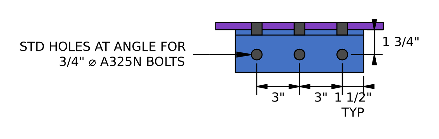
Section A-A at the beam. 角度, bolts and gage are the same as at the girder.
角度, 螺栓, holes and gages at the beam are the same as at the girder, so every check that depends only on them gives the same result:
| Check at the beam | Same as | 容量 | 直流电 |
|---|---|---|---|
| 细部, gusset side (angle horizontal edge governs) | 步 9 | 1.5 在 | 0.750 |
| 螺栓剪, gusset side | 步 10 | 53.677 基普 | 0.685 |
| Bearing on the angle, gusset side | 步 11 | 80.135 基普 | 0.459 |
| 有效强度, gusset side | 步 13 | 53.677 基普 | 0.685 |
| Angle block shear, gusset side | 步 14 | 61.365 基普 | 0.599 |
| Angle shear, gusset side | 步 16 | 62.395 基普 | 0.589 |
| Angle flexure, gusset side | 步 18 | 96.626 基普 | 0.381 |
| 相互作用, gusset side | 步 19 | 1.0 | 0.394 |
| Detailing at the beam | 步 20 | 1.75 在 | 0.857 |
| Bolt group to the beam (ICOR, C= 2.35) | 步 21 | 42.047 基普 | 0.874 |
| Bearing on the angle at the beam | 步 22 | 62.773 基普 | 0.586 |
| Effective strength to the beam | 步 24 | 42.047 基普 | 0.874 |
| Angle block shear, 梁侧 | 步 25 | 62.895 基普 | 0.585 |
| Angle shear, 梁侧 | 步 26 | 62.395 基普 | 0.589 |
| Angle flexure, 梁侧 | 步 27 | 138.04 基普 | 0.266 |
| 相互作用, 梁侧 | 步 28 | 1.0 | 0.323 |
In the gusset-side detailing, two rows change: the gusset end distance is 2.875 在 (直流电 0.348), and the minimum angle length becomes [mathin] h_{2}/2 = 5.875\,in [mathin] (直流电 0.653). Neither governs. The checks that involve the gusset dimensions or the beam web follow.
步 32: Bolt bearing and block shear of the gusset at the beam angle (AISC 360-16 J3.10, J4.3)
The gusset end distance at the beam is 2.875 在, so the end bolt has more material in front of it than at the girder.
[math] l_{c1} = (2.875\,in) – \frac{(0.8125\,in)}{2} = 2.4687\,in [math]
All three bolts still reach the 2.4 db 轴承盖, so the bearing strength is unchanged at 131.63 基普 (直流电 0.279). The block shear areas change with the end distance and the 11.75 in leg length:
[math] A_{gv} = (0.5\,in) \times \left[ (2.875\,in) + ((3) – 1) \times (3\,in) \right] = 4.4375\,in^{2} [math]
[math] A_{nv} = t_{gp} \left[ h_{2} – L_{ev,gp} – (n_{r} – 0.5)\left( d_{h} + 0.0625\,in \right) \right] = (0.5\,in) \times \left[ (11.75\,in) – (2.875\,in) – ((3) – 0.5) \times ((0.8125\,in) + (0.0625\,in)) \right] = 3.3438\,in^{2} [math]
和 [mathin] A_{nt} = 0.53125\,in^{2} [mathin] as at the girder:
[math] \phi R_{n} = (0.75) \times \left( 0.6 \times (65\,ksi) \times (3.3438\,in^{2}) + (1) \times (65\,ksi) \times (0.53125\,in^{2}) \le 0.6 \times (50\,ksi) \times (4.4375\,in^{2}) + (1) \times (65\,ksi) \times (0.53125\,in^{2}) \right) = 123.7\,kip [math]
DCR = 36.77 基普 / 123.7 基普= 0.297 < 1.0, 行
步 33: Gusset in shear along the beam angle (AISC 360-16 J4.2)
The gusset leg along the beam is 11.75 in long, so its shear areas grow with it.
[math] \phi R_{n,sy} = (1) \times 0.6 \times (50\,ksi) \times \left( (11.75\,in) \times (0.5\,in) \right) = 176.25\,kip [math]
[math] A_{nv} = (0.5\,in) \times \left[ (11.75\,in) – (3) \times ((0.8125\,in) + (0.0625\,in)) \right] = 4.5625\,in^{2} \qquad \phi R_{n,sr} = (0.75) \times 0.6 \times (65\,ksi) \times (4.5625\,in^{2}) = 133.45\,kip [math]
DCR = 36.77 基普 / 133.45 基普= 0.276 < 1.0, 行
步 34: 梁腹板上的螺栓轴承 (AISC 360-16 J3.10)
The beam web is slightly thicker than the girder web, 0.355 反对 0.35 在. As in Step 23, every bolt is an inner bolt:
[math] \phi R_{n} = (0.75) \times \min\left(1.2 \times (2.1875\,in),\, 2.4 \times (0.75\,in)\right) \times (0.355\,in) \times (65\,ksi) \times (2.35) = 73.205\,kip [math]
DCR = 36.77 基普 / 73.205 基普= 0.502 < 1.0, 行
Per bolt, the beam web gives 31.151 基普. That is still more than the 17.892 kip bolt shear, so the effective strength of the bolts to the beam stays at 42.047 基普 (直流电 0.874).
步 35: Gusset in bending at the beam (AISC 360-16 F11.1)
This is the same check as Step 29, using the gusset width and leg length at the beam.
[math] M_{T} = V_{r} \left( o_{2} + b_{2} \right) = (36.77\,kip) \times \left( (1\,in) + (6.5\,in) \right) = 22.981\,kip{\cdot}ft [math]
[math] \phi M_{n} = \frac{\phi\, F_{y,gp}\, t_{gp}\, h_{2}^{2}}{4} = \frac{(0.9) \times (50\,ksi) \times (0.5\,in) \times ((11.75\,in))^{2}}{4} = 64.717\,kip{\cdot}ft [math]
DCR = 22.981 基普英尺 / 64.717 基普英尺 = 0.355 < 1.0, 行
步 36: Gusset in buckling at the beam (AISC 360-16 F11.2)
This is the same check as Step 30. The lever arm now runs out to the middle of the girder leg, [mathin] o_{2} + b_{2} + h_{1}/2 [mathin], and the section is the 11.75 in beam leg.
[math] M_{C} = V_{r} \left( o_{2} + b_{2} + \frac{h_{1}}{2} \right) = (36.77\,kip) \times \left( (1\,in) + (6.5\,in) + \frac{(11\,in)}{2} \right) = 39.834\,kip{\cdot}ft \qquad L_{b} = 13\,in [math]
[math] S_{x} = 11.505\,in^{3},\ Z_{x} = 17.258\,in^{3},\ M_{y} = 47.938\,kip{\cdot}ft,\ M_{p} = 71.908\,kip{\cdot}ft [math]
[math] \frac{L_{b}\, h_{2}}{t_{gp}^{2}} = \frac{(13\,in) \times (11.75\,in)}{((0.5\,in))^{2}} = 611 [math]
[math] M_{cr} = \min\left[ (1) \times \left[ 1.52 – \frac{0.274 \times (611) \times (50\,ksi)}{(29000\,ksi)} \right] \times (47.938\,kip{\cdot}ft),\ (71.908\,kip{\cdot}ft) \right] = 59.029\,kip{\cdot}ft [math]
[math] \phi M_{cr} = (0.9) \times (59.029\,kip{\cdot}ft) = 53.126\,kip{\cdot}ft [math]
DCR = 39.834 基普英尺 / 53.126 基普英尺 = 0.750 < 1.0, 行
The beam leg is longer and deeper than the girder leg, so it buckles at a higher moment, and its ratio is lower than the 0.893 at the girder.
检查摘要
| 设计检查 | 需求 | 容量 | 直流电 | 结果 |
|---|---|---|---|---|
| Brace bolts: 细化 | 1.063 在 | 1.500 在 | 0.709 | 通过 |
| Brace bolts: 滑 | 52 基普 | 64.546 基普 | 0.806 | 通过 |
| Gusset bearing at the brace | 52 基普 | 323.58 基普 | 0.161 | 通过 |
| Brace bearing | 52 基普 | 291.99 基普 | 0.178 | 通过 |
| Gusset block shear at the brace | 52 基普 | 260.81 基普 | 0.199 | 通过 |
| Brace block shear | 52 基普 | 238.07 基普 | 0.218 | 通过 |
| Gusset tension (Whitmore) | 52 基普 | 350.81 基普 | 0.148 | 通过 |
| 支撑张力断裂 | 52 基普 | 253.14 基普 | 0.205 | 通过 |
| Girder angle: 细化, gusset side | 1.125 在 | 1.500 在 | 0.750 | 通过 |
| Girder angle: 螺栓剪, gusset side | 36.77 基普 | 53.677 基普 | 0.685 | 通过 |
| Girder angle: bearing on the angle, gusset side | 36.77 基普 | 80.135 基普 | 0.459 | 通过 |
| Girder angle: bearing on the gusset | 36.77 基普 | 131.63 基普 | 0.279 | 通过 |
| Girder angle: effective strength, gusset side | 36.77 基普 | 53.677 基普 | 0.685 | 通过 |
| Girder angle: angle block shear, gusset side | 36.77 基普 | 61.365 基普 | 0.599 | 通过 |
| Girder angle: gusset block shear | 36.77 基普 | 118.22 基普 | 0.311 | 通过 |
| Girder angle: angle shear, gusset side | 36.77 基普 | 62.395 基普 | 0.589 | 通过 |
| Girder angle: gusset shear | 36.77 基普 | 122.48 基普 | 0.300 | 通过 |
| Girder angle: angle flexure, gusset side | 36.77 基普 | 96.626 基普 | 0.381 | 通过 |
| Girder angle: 相互作用, gusset side | 0.394 | 1.000 | 0.394 | 通过 |
| Girder angle: detailing at the girder | 1.500 在 | 1.750 在 | 0.857 | 通过 |
| Girder angle: bolt group to the girder (ICOR) | 36.77 基普 | 42.047 基普 | 0.874 | 通过 |
| Girder angle: bearing on the angle at the girder | 36.77 基普 | 62.773 基普 | 0.586 | 通过 |
| Girder angle: bearing on the girder web | 36.77 基普 | 72.174 基普 | 0.509 | 通过 |
| Girder angle: effective strength to the girder | 36.77 基普 | 42.047 基普 | 0.874 | 通过 |
| Girder angle: angle block shear, girder side | 36.77 基普 | 62.895 基普 | 0.585 | 通过 |
| Girder angle: angle shear, girder side | 36.77 基普 | 62.395 基普 | 0.589 | 通过 |
| Girder angle: angle flexure, girder side | 36.77 基普 | 138.04 基普 | 0.266 | 通过 |
| Girder angle: 相互作用, girder side | 0.323 | 1.000 | 0.323 | 通过 |
| Gusset bending at the girder | 23.747 基普英尺 | 56.719 基普英尺 | 0.419 | 通过 |
| Gusset buckling at the girder | 41.749 基普英尺 | 46.766 基普英尺 | 0.893 | 通过 |
| Beam angle: checks matching the girder angle | 36.77 基普 | see Step 31 | 0.874 最高 | 通过 |
| Beam angle: 细化, gusset side | 1.125 在 | 1.500 在 | 0.750 | 通过 |
| Beam angle: bearing on the gusset | 36.77 基普 | 131.63 基普 | 0.279 | 通过 |
| Beam angle: gusset block shear | 36.77 基普 | 123.7 基普 | 0.297 | 通过 |
| Beam angle: gusset shear | 36.77 基普 | 133.45 基普 | 0.276 | 通过 |
| Beam angle: 梁腹板上的轴承 | 36.77 基普 | 73.205 基普 | 0.502 | 通过 |
| Gusset bending at the beam | 22.981 基普英尺 | 64.717 基普英尺 | 0.355 | 通过 |
| Gusset buckling at the beam | 39.834 基普英尺 | 53.126 基普英尺 | 0.750 | 通过 |
Every check in this horizontal brace connection design passes. Gusset buckling at the girder governs at 0.893: the girder leg of the gusset is the shorter of the two, so it has the smaller section and the longer lever arm to the middle of the other leg. The eccentric bolt groups to the girder and the beam come next at 0.874, followed by slip of the brace bolts at 0.806.
如果检查失败要更改什么
- Gusset buckling or bending: use a thicker gusset, which raises the section and lowers the slenderness parameter at the same time. Lengthening the leg along the member also helps. Reducing the gusset width, and with it the lever arm, works where the brace geometry allows.
- Bolt group to the girder or beam: add a bolt row to the angle, 或使用更大的螺栓. A smaller gage on the member leg reduces the eccentricity but has to stay above the minimum gage.
- Brace bolt slip: use a Class B surface (μ = 0.5 代替 0.3), 添加螺栓行, or use standard holes in the gusset where the erection tolerance allows, which raises φ to 1.00.
- Angle shear, block shear or flexure: use a longer or thicker angle. A longer angle also adds room for another bolt row.
- Bearing on a thin member web: add a bolt row so each bolt carries less, or use a larger bolt diameter.
- Whitmore section or block shear at the brace: lengthen the bolt group to widen the Whitmore section, 或者使用更厚的角撑板.
经常问的问题
How is the brace force shared between the girder and the beam?
The report resolves the 52 kip brace force into two components at the brace angle of 45 度数. The component along the girder goes to the girder angle, and the component along the beam goes to the beam angle, 36.77 kip each. Each single angle then carries its share as shear along its own bolt line. There is no Uniform Force Method distribution as there is in a vertical brace connection.
Why do the brace bolts have only one slip plane?
Both brace angles lie flat on the same face of the gusset, side by side with a 6 inch gage between their bolt lines. Each bolt passes through one angle leg and the gusset, so there is a single faying surface per bolt. When the gusset sits between two angles, as in many vertical braces, each bolt clamps two surfaces and the slip strength doubles.
Why are the brace bolts slip critical but the angle bolts are not?
The gusset has oversized holes at the brace to give the erector room to fit up the bay. AISC 360-16 J3.2 仅允许在滑动关键接头中使用过大的孔. The single angles use short slots on the gusset leg, oriented so the load runs across the slot, and J3.2 allows that in a bearing-type joint. Those bolts are A325N, checked for shear and bearing.
Why is the single angle checked like a coped beam?
The force enters the angle at one bolt line and leaves at the other leg, so the leg between them is a short, deep cantilever. A thin, deep plate in bending can buckle laterally. The AISC Manual’s double-coped beam procedure covers a rectangular section like this, so the report uses it, with the bolt gage as the unbraced length and the angle length as the depth.
Why does gusset buckling govern this connection?
The gusset is a half inch plate that wraps around the column, and the force on each leg acts at a long lever arm to the middle of the other leg. That gives a large in-plane moment on a section with a long free edge. Buckling caps the strength below the plastic moment, and the shorter girder leg ends up at a ratio of 0.893.
Why is the bolt group coefficient 3 on the gusset leg but 2.35 on the member leg?
On the gusset leg the bolts are a single row with a small eccentricity, and the AISC Manual lets you neglect an eccentricity of 3 英寸或更小, so the coefficient is the bolt count. On the member leg the report takes the 1.75 inch gage as the eccentricity and runs the instantaneous center of rotation method, 这给出了 2.35.
对于 AISC ASD 而不是 LRFD 来说,这会如何变化?
极限状态和标称强度相同. With AISC ASD you compare service-level forces against the nominal strength divided by a safety factor. 阻力系数为 0.75 成为安全系数 2.00, 0.90 变成 1.67, 带有超大孔的滑移来自 0.85 至 1.76. The split of the brace force between the girder and the beam is unchanged.
Design a horizontal brace connection for free
此页上的每个数字都来自一个解决方案. Pick the horizontal bracing configuration, enter your members, 支撑, 角撑板, 角度, bolts and forces, and the free calculator runs each of these checks in your browser without anything to install.
SkyCiv Connection Design 模块是本示例背后的连接设计软件. 它为您提供完整的计算报告,其中包含每个方程和您的数字, 就像上面的步骤一样, 加上每个容量和 DCR, 对于AISC 360-16 (LRFD 和 ASD) 并作为 4100:2020.
参考资料
- AISC 360-16, 钢结构建筑规范: B4.3, D3 (表 D3.1 案例 2), F11.1, F11.2 (情商. F11-2), J3.2, J3.3, J3.4 (表J3.4), J3.5 (表 J3.5), J3.6 (情商. J3-1), J3.8 (情商. J3-4, 表J3.1), J3.10 (情商. J3-6a, J3-6c), J4.1 (情商. J4-1, J4-2), J4.2 (情商. J4-3, J4-4), J4.3 (情商. J4-5).
- AISC 钢结构手册, 15第版: 部分 7 (瞬时旋转中心, 情商. 7-1), 部分 9 (图. 9-1 惠特莫尔区, 情商. 9-4, 情商. 9-15), 部分 10 (p. 10-116 eccentricity of a single row, 情商. 10-5), 部分 15 (桌子 15-3).
- 使用 AISC 进行钢连接设计 360-16
- 螺栓 SkyCiv 连接设计

哈罗德穆纳勒姆
产品经理, 连接设计
10+ 从事钢结构连接设计多年
领英

