When learning new software, engineers usually expect to commit weeks to learning and mastering the software before they truly can become efficient in its use. Sometimes, that is a barrier to trying new software, especially when the test project is quite unique with a tight schedule and budget. In Stuart Agar's case, he was able to take SkyCiv into a fun and interesting project with almost zero downtime. This Featured Project article will highlight his unique project and how he used DXF importing, P-delta and dynamic frequency analysis to design the project.
North Yorkshire Farm House Redevelopment, Nork Yorkshire, England, UK
Type: Residential
Engineer: Stuart Agars from Struct-Sure Limited
Struct-Sure Limited is a small structural engineering design company based in the northern England, who provide a wide of structural engineering services in the commercial sector. They also pride themselves on their expertise in the structural engineering and design of high quality, luxury residential and domestic developments using a variety of materials, including engineered timber, structural insulated panel, and Glulam, among others. The engineer, Stuart Agars, Managing Director of Struct-Sure Limited, has more than 30 years of experience in the structural engineering industry and in using a variety of structural engineering software.
Even after 30 years of hand calculations, different types of software, Stuart was able to pick up SkyCiv and soon found it to be his go to tool for this project: “Struct-Sure went to market to look for a new suite of 3D analysis software in 2017 when their current software licence came up for renewal. After some very through product testing and market research we decided to go with SkyCiv."
About the Project
Located in rural North Yorkshire in England, the project was considered a large residential luxury development. It started with the demolition of a traditional 1970's home, followed by a custom design of new, energy efficient, contemporary home equipped with multiple garages, workshops and stables. All of these elements were designed to have the same consistent aesthetic. Its budget sat around £2 million, including land costs. The design and construction team consisted of five separate parties, including Struct-sure, so there many voices needed to heard during the design and construction process. Inside the main building there is a suspended mezzanine floor as well as a steel spiral staircase with glass balustrades.
What makes this project especially unique is the "three-sided glazing". The glass panels shown in the project photos are the largest available glazing panels for fabrication in Europe, and stand at 5.5 meters (18 feet) tall! These panels were the centerpiece of the design, but also caused some interesting design challenges.
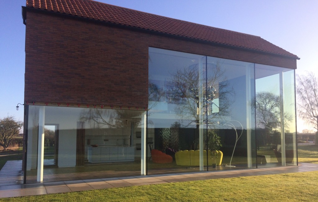
Figure 1: Facade of the structure showing the 5.5m record setting glazing.
The Challenge
The culmination of modern architectural design features, client requests, and the 3-sided glass panels let to some interesting structural challenges, to say the least. All together, these challenges took a rudimentary residential project and turned it on it's head. The main problem that Stuart faced was when he found out that the entire architectural set for the project set was done in 2D, with no 3D model available. With the complexity of the project, designing the structure entirely based on 2D drawings would have meant an insane amount of collaboration and meetings.
In terms of design, the major challenges included:
- Three-Sided Glazing - required glass-to-glass joints on the front, gable & rear elevation. The glazing had to be designed frame-less - the client would not consider seeing glazing frames.
- Visible Bracing not Permitted - the client wanted no obstructions when looking out the 5.5m tall windows. This meant moment steel frames were the only laterally restraining method available.
- No Sway Permitted - the steel moment, or 'sway' frames, were not allowed to sway due to the glazing construction. The tall frame-less glazed panels restricted deflection almost entirely.
- Column Restrictions - Steel columns were to be of "slimline" (minimal) profile, and were located set back from the glazing inside the building envelope. This restricted the sizing of members available.
- Eccentric Exterior Loading - Outer leaf Masonry Panels were hung (with eccentricity) over glazed panels, causing some extreme loading situations on not just the glazing, but the attached superstructure.
- No Visible Gutters or Rain Water Goods - This posed a collaboration challenge between Stuart and the architectural team. Special adjustments to the structure were needed to accommodate room for interior hiding/storage of these features.
- Upper Floor Limitations - The upper floor needed to be of "slimline" profile when viewed from the double height living space below, and no down-stand beams were allowed. The resulting solution was to hand the entire elevated floor diaphragm from the roof structure.
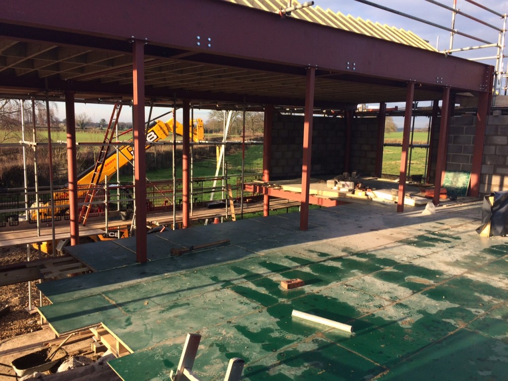
Figure 2: Suspended elevated floor hung from roof steel with steel tubes.
How it was Designed
Stuart used SkyCiv Structural 3D to model and analyze the steel frame of the building. He modeled one direction of the building as a braced structure, including braces only in locations where the glazing was not present. The other direction - consisting mostly of glazing - was designed using a series of moment frames with fully fixed base connections. Both frames were modeled using the various tools available in Structural 3D, while taking advantage of the end fixity presets available. Linear Static Analysis was used for this project initially, while the P-Delta analysis was ran as a back checking method. After the project was designed, SkyCiv released Dynamic Frequency Analysis to the platform; Stuart plans on utilizing this feature in his next design.
The slimline and floating aesthetic of the upper floor meant that no more than 200mm (8 inches) of overall thickness, including finishes, was allowed. The subsequent hanging steel tubes were designed as tension only members using that setting in Structural 3D. One of the more interesting design pieces of this project was the connection between the interior round columns and the steel channels that supported the glazing. What Stuart came up with was a modular connection that was prefabricated before being sent to the site. See Figure 3 for the corner connection detail.
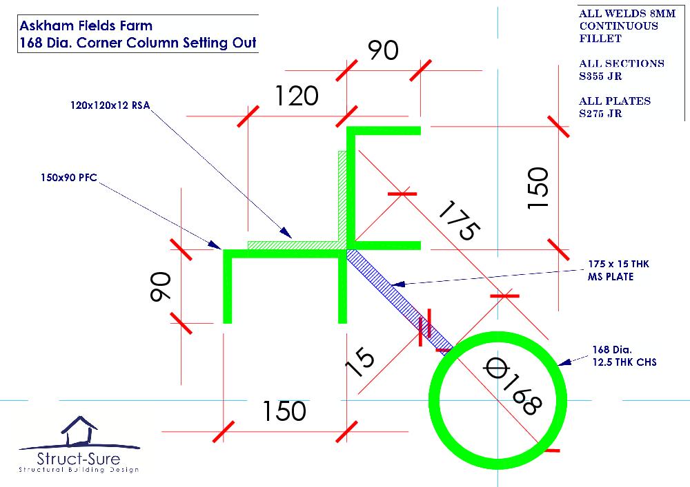
Figure 3: Unique Connection between CHS columns and exterior channel members.
How SkyCiv Helped
Portability, 3D Collaboration, and DXF File Import
To remedy the most blatant issue of not having a 3D model, Stuart modeled the structure in conjunction with the architectural drawings in Structural 3D. This allowed him and the rest of the design team to visualize the structure not just from a structural engineer's perspective, but from a contractor's and architect's perspective. This drastically accelerated the design meetings and subsequently the design process, saving the client time and money on the project. Thanks to SkyCiv being cloud-based, he was able to bring the model directly to the architect and client. He was also able to get a jump start on some of the complex geometry by taking advantage of the DXF import tool available in Structural 3D, saving him even more time in the modeling process.
Here is what Stuart had to say about the 3D model's role in the project:
" It was difficult for the team to start to detail the frame without a 3D model. Using SkyCiv Structural 3D I was able to very quickly produce a preliminary 3D model in SkyCiv and present the rendered model to the team in the very early stages of the project. Without the ability to build the 3D model quickly for the first design team meeting, the project would have stayed in the design phase for a significant time longer than it did, since each member of the team would've had to produce 2D drawings to each other for approval. As a design team were were able to open the model in the meeting, spin it around, and discuss all of the complex areas."
The model also posed some benefits to the steel supplier and erector:
"The steel-work supplier and erector could use the SkyCiv model to "Node Out" his connections and discuss how he would prefer to weld up and bolt the very complex steel connections - this process was the real key to the project."
Not only did modeling the structure save him time during his analysis and design, it aided the entire project team.

Figure 4: The SkyCiv Structural 3D rendering of the project. This accelerated the design process and made collaborating a breeze.
Easy to Learn and Cost Effective
Stuart did not expect to become efficient using the SkyCiv software platform as soon as he did. Engineers have grown accustomed to hard to learn software that requires hours and hours of learning and upstart time. Much of the time there is no trial period and the cost of the software is too high, therefore creating a barrier from some engineers even trying it. This combination of time and monetary commitment leads to engineers getting stuck using software that they have always used, simply because it is not worth trying to learn a new one. Subsequently, this disincentivizes innovation.
"Commercially, SkyCiv makes good business sense for our company. The monthly subscription for SkyCiv attracted me at first, rather than paying a large lump sum upfront. When I tested SkyCiv Structural 3D, I found it very easy to use (and by a long-shot). It was easily the most intuitive package available to learn; it is particularly easy to build the 3D model and define nodes, members, supports, materials, sections, then apply loads & combinations. Also, I followed the SkyCiv YouTube channel if I wasn't sure how to build, manipulate or modify my model."
Want to try SkyCiv? Get started for free today!