Steel Silo Structure using Plates and Shell Elements
Learn how to use SkyCiv Shell Elements to model and analyse a silo structure with hydrostatic loads.
In this walkthrough we’ll look at two ways to model a structure like this. (1) using the Excel Plugin and (2) using the built-in features of SkyCiv Structural 3D. We will mainly focus on (2), using the modeling operations and meshing capabilities of S3D.
[BONUS] Using the SkyCiv Excel Plugin
Excel is an extremely powerful tool as the built-in formulas make complex geometry calculations easy. SkyCiv has a one-click installation available for our Excel plugin. Adding a few parameters, then using the standard calculations (in this case COS, SIN) to build your silo model.
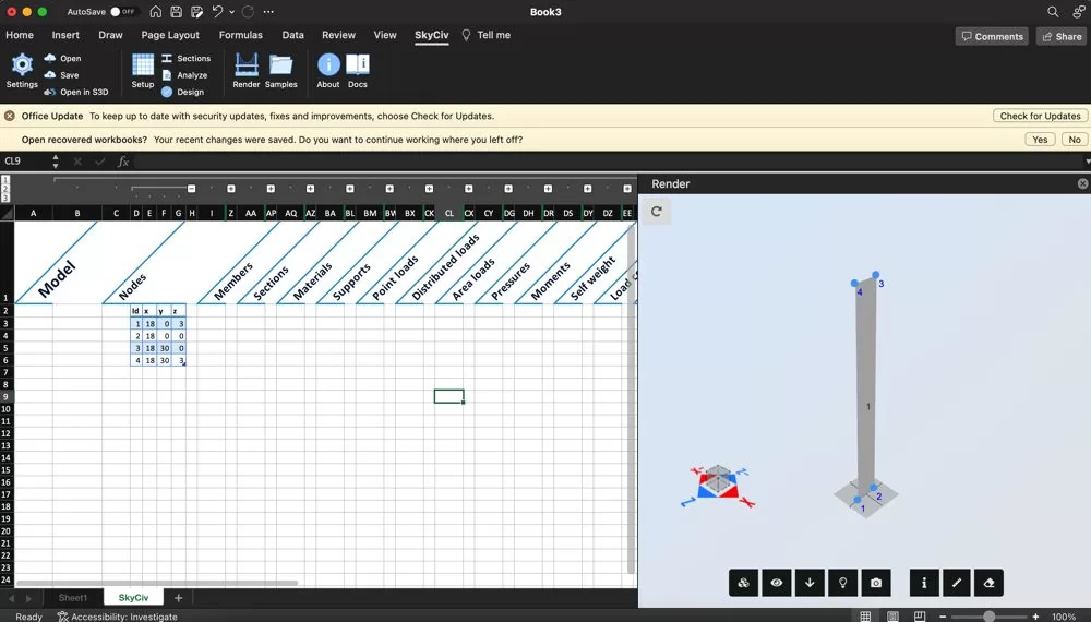
The plugin would be the preferred method if this is a common structure. Spending more time in generating models from a few parameters would save hours in the long run. Saving this template to use time and time again for your silo structures would be a great time saver!
Model a single plate strip
When modelling silos, it’s often easier to start with a single element and then rotate that element to form the basis of your model. We want to create one single strip, that is offest from the centre, then rotate about that centre point to complete the structure. To do this, we’ll do some simple calculations to understand how many segments we will need and the degree between segments:
- Diameter of the structure, in this example, 6ft
- We want to create a ‘circular’ structure broken up into 60 segments
- Therefore, we need 360/60 = 6 degrees between each segment
- The position of each strip can be calculated using COS & SIN the diameter
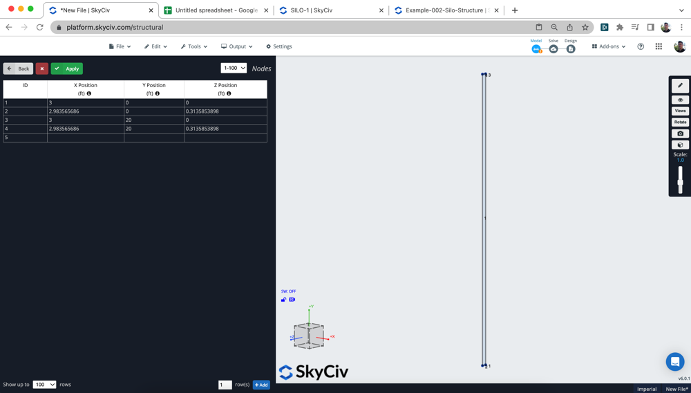
Entering these nodes into the datasheet to form the corner nodes for our first plate. You can add a plate quickly by (a) highlighting all the nodes (2) then right click the GUI and click Add Plate. The software will automatically put your nodes into clockwise direction and add the plate for you! This becomes even more helpful when it comes time to add our more complex top and bottom plates.
Apply your Hydrostatic Pressures
Using linear pressures, we can add hydrostatic pressures to simulate the increasing pressures applied from the water or whatever other liquid is present in your silo. Our plan here is to build a single segment, with a single pressure:
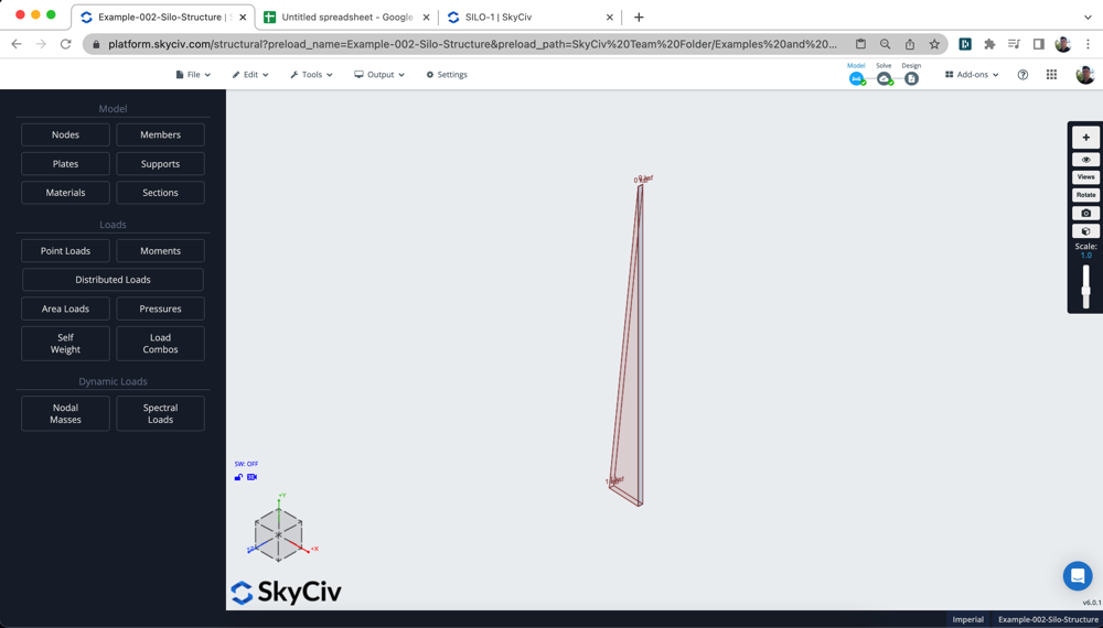
Linear Pressures are added by adding P1, P2, P3 (the three nodes to dictate the pressure direction) and then M1,M2,M3 (the magnitude of the pressures for each of those points). In the above example, you can see we have added 1kip for the first two points, and 0kip for the third point – creating a triangular pressure.
Rotate/Repeat your Strip
Once you’re happy with your single strip, it’s time to rotate/repeat it. Highlight your strip, then click Operations – Rotate, which will show the following input:
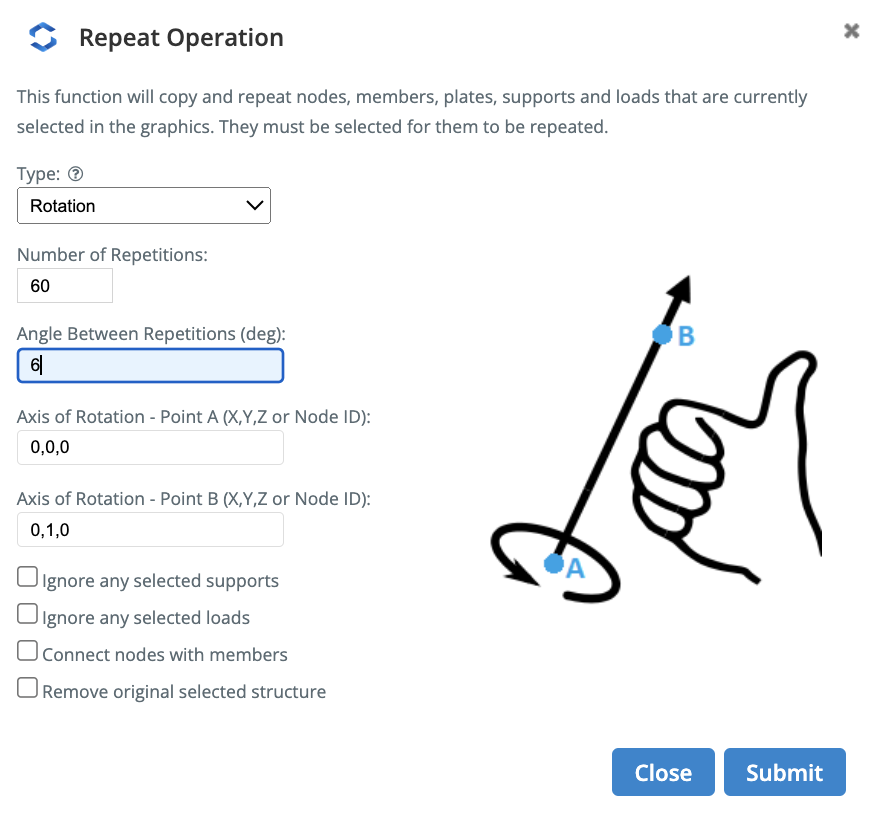
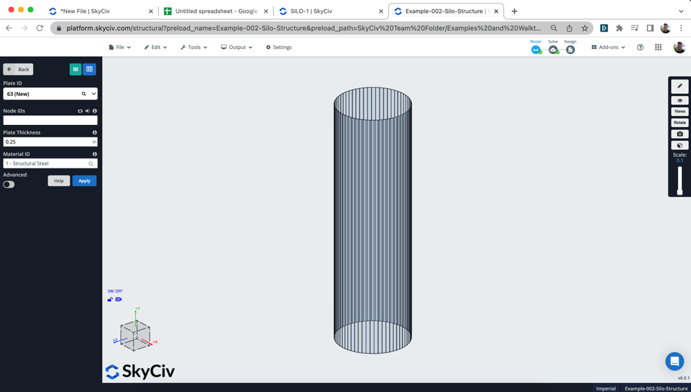
Add the number of repetitions, the angle between repetition and then the axis (in this case we are rotating about the vector 0,1,0 from the global axis). Once submitted, you should see the vertical walls of your silo complete. Note: The repeat will also repeat your hydrostatic pressures, they have just been hidden for simplicity:
Mesh your Plates
To generate a more accurate analysis model, we want to mesh the plates into smaller elements. We support two types of meshing, each with it’s own advantage:
- StructuredQuadrilateral – these are useful for meshing rectangular plates. We will use this for the vertical plates, so we can create nice square isometric meshes since we can control the b and h divisions
- Unstructured Quadrilaterals – these are ideal for complex plate shapes. In this case, the top lid and base of the cylinder.
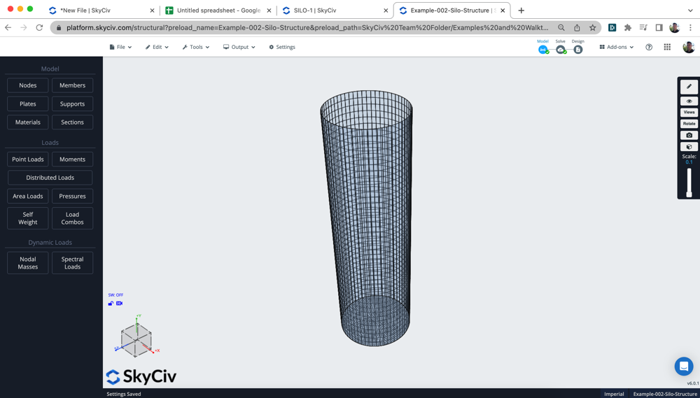
Using a combinations of these we can mesh our silo. Selecting the vertical walls, then right-click Mesh Plate and doing the same for the base plate:
Add Surface Spring Support
We can add a surface spring support to simulate the soil’s spring interaction with the structure. To add this type of support system, simply select the plate and click Add Surface Spring Support under the Supports option. This will open the following input:
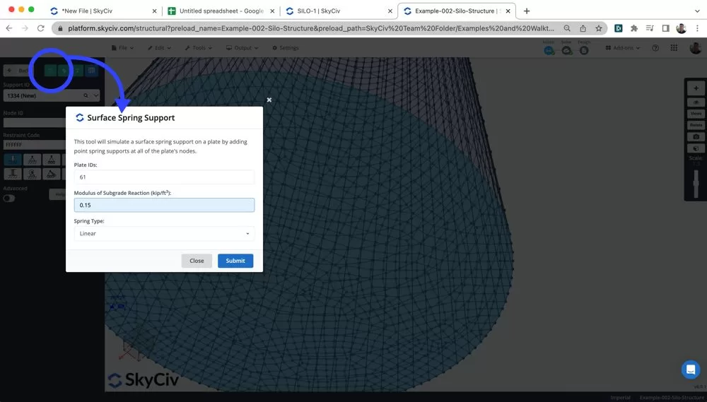
Users can then enter the Modulus of Subgrade Reaction for their soil, which is typically taken form a geotechnical report for your site location. The software will automatically translate this to a spring stiffness constant for the spring support. This type of support is typical when your structure is sitting on soil. However, if your structure is build on some other support system, you would obviously use a different type of support.
Solving & Reviewing
By now, you should by now have the following complete:
- Your geometry of your plates are set, including plate thickness
- Material properties of your plates (in this example we are using the preset Structural Steel) but this material should be reviewed for your particular case
- Plates all meshed
- Pressures Applied, you can also add additional loads for wind, snow etc…
- Boundary Conditions Defined
You’re finally ready to solve! Click Solve in the top right corner to perform the analysis. Depending on the number of meshed elements you have, this might take a minute or so.
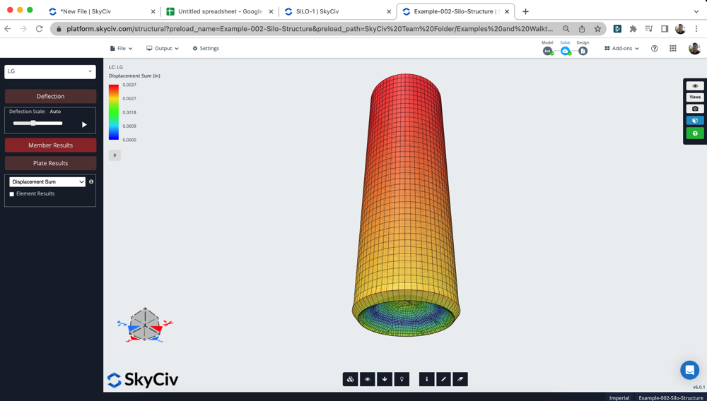
You can now review your analysis results by clicking Plates and turning on a particular result. In this case, we are looking at the Displacement Sum results to review the model is connected and built correctly. By scaling the deflection (S + Scroll) you should be able to review any obvious issues or problems in your model.
FAQ
k = p/s
k = Modulus of Subgrade Reaction
p = Applied Pressure
S = soil displacement
The unit is kip/ft3, as it represents the amount of applied pressure to the soil deformation.
This is completely dependant on the soil profile and should be determined by a geotechnical engineer or appropriate geotechnical report.
However, for example sake a typical Modulus of Subgrade Reaction for compacted sand could be 0.05 – 0.15 MPa/mm
You can also mesh your entire model in one single click. To do this, select all your plates and click AutoMesh. The benefit of doing it this way, is that all your plates will be properly connected and it will automatically connect any internal nodes and members.
This is beneficial for more complex structures and models, however in this case most of the plates and model was symmetrical so we could use the manual meshing process.

