
To design a single plate shear connection (a shear tab) to AISC 360, you check the bolts, the plate and the weld against the beam end reaction. That means bolt shear, bolt bearing and tear-out, block shear, plate shear yielding and rupture, plate flexure, and weld strength, plus the detailing and ductility limits that keep the connection flexible enough to act as a simple support.
This page works through one real example from start to finish: a W18x35 beam framing into the flange of a W14x90 column, with a 50 kip LRFD reaction, three 1 in A490-N bolts and a 1/2 in plate, designed to AISC 360-16 and the AISC Manual 15th Edition. Every equation is written out with its numbers, in the same order as the AISC calc sheet the SkyCiv Connection Design module produces for it.
What is a single plate shear connection?
A single plate shear connection is a steel plate shop-welded to the supporting member and field-bolted to the web of the supported beam. It transfers the beam’s end shear, and it is classified as a simple connection under AISC 360-16 B3.4, so it is detailed to rotate rather than resist moment. It is also called a shear tab or shear plate.
It is the most common shear connection in US steel buildings because it needs one plate, one weld and one line of bolts, and the beam can be swung into place from the side during erection. The alternatives for the same job are the double angle connection, the single angle connection and the shear end plate connection. You can check this one directly in the single plate connection calculator.
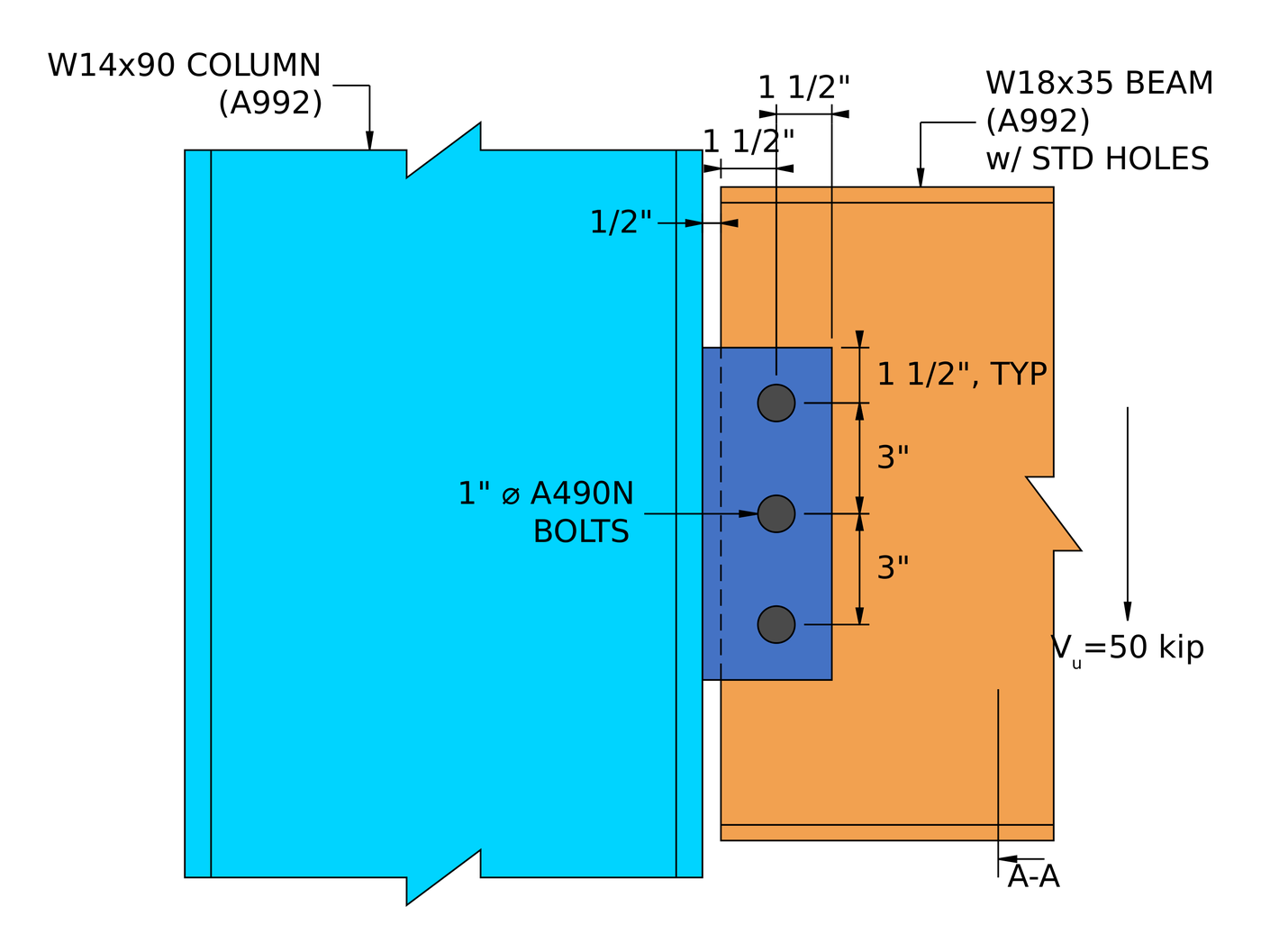
Elevation of the example connection. The plate is welded to the column flange and bolted to the beam web, with the bolt line 2 in from the weld.
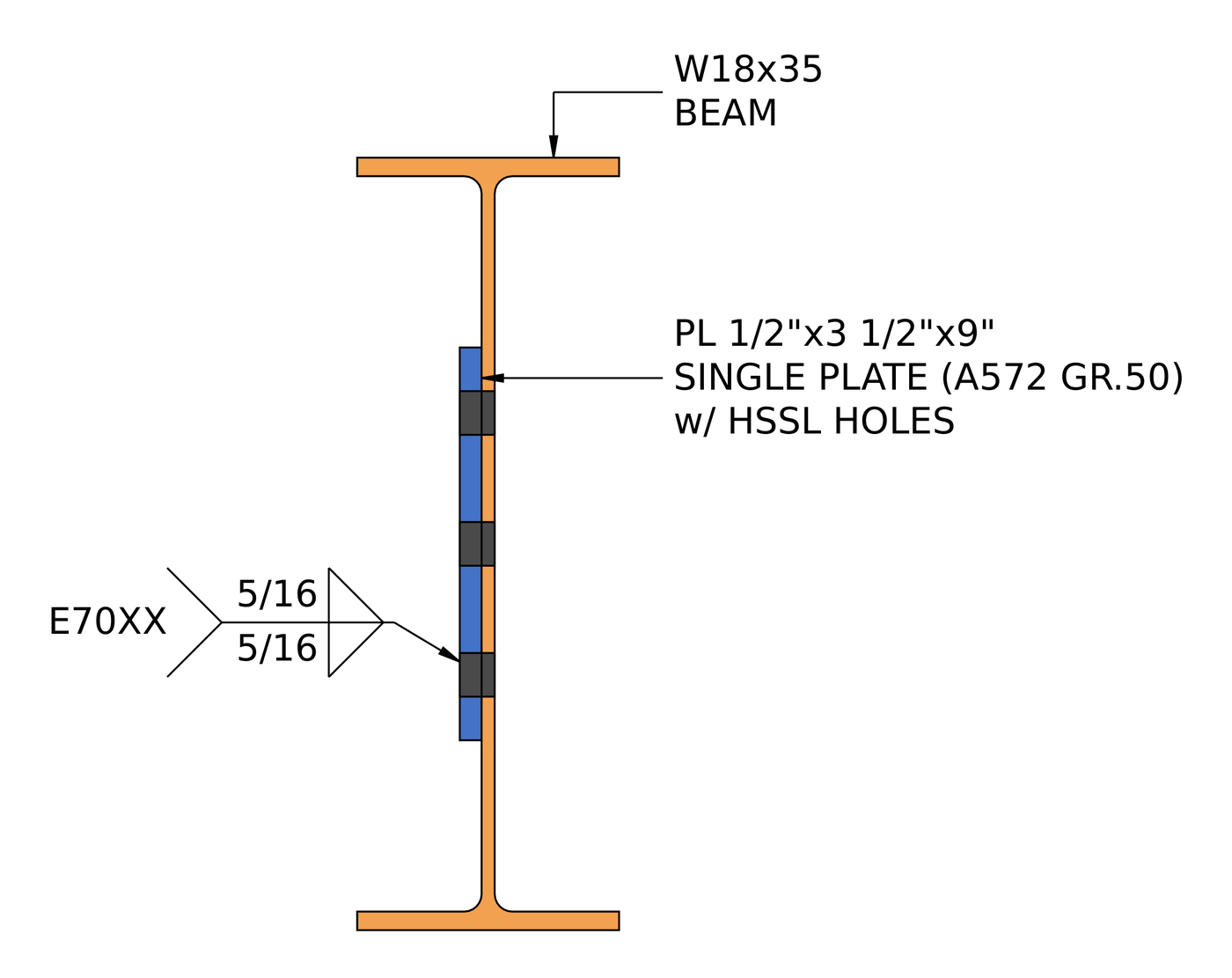
Section A-A. The plate has horizontal short-slotted holes and a 5/16 in fillet weld on both sides.
How do you design a single plate shear connection? The steps at a glance
- Check the detailing limits at the beam: bolt spacing, edge distances, plate depth.
- Find the bolt group shear strength with the instantaneous center of rotation.
- Check plate ductility: the plate must not be stronger than the bolts.
- Check bolt bearing and tear-out on the plate.
- Check bolt bearing and tear-out on the beam web.
- Combine shear, bearing and tear-out per bolt for the effective group strength.
- Check block shear of the plate.
- Check shear yielding and shear rupture of the plate.
- Check plate flexure using the double coped beam procedure.
- Check shear and flexure interaction, for yielding and for rupture.
- Check the detailing limit at the support.
- Size the weld to develop the plate.
- Check the weld strength to the column flange.
Design inputs for this example
The design code is AISC 360-16 LRFD. Section properties are from the AISC Manual.
| Item | Symbol | Value |
|---|---|---|
| Factored vertical shear | [mathin] V_{u} [mathin] | 50 kip |
| Beam | W18x35, A992 | |
| Beam depth | [mathin] d_{bm} [mathin] | 17.7 in |
| Beam web thickness | [mathin] t_{wb} [mathin] | 0.3 in |
| Beam flange width / thickness | [mathin] b_{fb},\ t_{fb} [mathin] | 6 in / 0.425 in |
| Beam yield / tensile stress | [mathin] F_{yb},\ F_{ub} [mathin] | 50 ksi / 65 ksi |
| Column | W14x90, A992 | |
| Column flange thickness | [mathin] t_{fs} [mathin] | 0.71 in |
| Column yield / tensile stress | [mathin] F_{ys},\ F_{us} [mathin] | 50 ksi / 65 ksi |
| Modulus of elasticity | [mathin] E [mathin] | 29000 ksi |
| Item | Symbol | Value |
|---|---|---|
| Plate (single plate) | PL 1/2 x 3 1/2 x 9, A572 Gr. 50 | |
| Plate width / depth / thickness | [mathin] b_{p},\ d_{p},\ t_{p} [mathin] | 3.5 in / 9 in / 0.5 in |
| Plate yield / tensile stress | [mathin] F_{yp},\ F_{up} [mathin] | 50 ksi / 65 ksi |
| Bolts | 1 in A490-N, single shear | |
| Bolt diameter | [mathin] d_{b} [mathin] | 1 in |
| Bolt nominal tensile / shear stress | [mathin] F_{nt},\ F_{nv} [mathin] | 113 ksi / 68 ksi |
| Shear planes | [mathin] N_{s} [mathin] | 1 |
| Holes in plate / beam | Short-slotted horizontal (HSSL) / standard (STD) | |
| Weld | 5/16 in fillet, both sides, E70XX | |
| Weld size / filler strength | [mathin] W,\ F_{EXX} [mathin] | 0.3125 in / 70 ksi |
| Geometry | Symbol | Value |
|---|---|---|
| Bolt rows / row spacing | [mathin] n_{r},\ s_{r} [mathin] | 3 / 3 in |
| Bolt columns / column spacing | [mathin] n_{c},\ s_{c} [mathin] | 1 / 0 in |
| Beam web clearance to column | [mathin] clr [mathin] | 0.5 in |
| Horizontal edge distance on beam web | [mathin] L_{eh,bm} [mathin] | 1.5 in |
| Horizontal edge distance on plate | [mathin] L_{eh,pl} [mathin] | 1.5 in |
| Vertical edge distance on plate | [mathin] L_{ev,pl} [mathin] | 1.5 in |
| Weld line to bolt line | [mathin] a = e [mathin] | 2 in |
Step 1: Detailing limits at the beam side (AISC 360-16 J3.3, J3.4)
Before any strength check, the bolt layout has to be buildable and match the assumptions behind the strength equations. Bolts that are too close tear between the holes, edges that are too close tear out, and a plate that is too short or too deep changes how the connection rotates.
The minimum bolt spacing is [mathin] 2\tfrac{2}{3} d_{b} [mathin] from J3.3. The minimum edge distance for a 1 in bolt is 1 1/4 in from Table J3.4. On the plate, the horizontal edge is measured across the short slot, so the Table J3.5 increment raises it to 1.375 in. The plate depth has to be at least half the beam’s T dimension, so the connection is stiff enough to brace the beam end, and it must also fit inside the beam web.
[math] s_{min} = 2\tfrac{2}{3}\, d_{b} = 2.667 \times (1\,in) = 2.667\,in [math]
| Detailing limit | Limit (in) | Actual (in) | DCR | Result |
|---|---|---|---|---|
| Minimum bolt row spacing | 2.667 | 3.000 | 0.889 | PASS |
| Maximum bolt row spacing | 6.000 | 3.000 | 0.500 | PASS |
| Plate minimum vertical edge distance | 1.250 | 1.500 | 0.833 | PASS |
| Plate minimum horizontal edge distance | 1.375 | 1.500 | 0.917 | PASS |
| Beam minimum horizontal edge distance | 1.250 | 1.500 | 0.833 | PASS |
| Minimum connection depth | 7.750 | 9.000 | 0.861 | PASS |
| Maximum connection depth | 16.000 | 9.000 | 0.563 | PASS |
For a minimum limit the ratio is limit over actual, and for a maximum it is actual over limit. The governing row is the plate horizontal edge distance:
[math] DCR = \frac{1.375\,in}{1.5\,in} = 0.917 [math]
DCR = 0.917 < 1.0, OK
Step 2: Bolt group shear strength by the instantaneous center of rotation (AISC 360-16 J3.6)
The beam reaction acts away from the bolt line, so the bolts carry a small moment as well as the shear. The instantaneous center of rotation (ICOR) method finds the point the bolt group rotates about and turns that into a coefficient C, which is how many bolts’ worth of shear strength the group actually delivers.
Design eccentricity
The bolt line is 2 in from the weld, but the bolt group is designed for an eccentricity of 1 in, because AISC Manual Table 10-9 sets the design eccentricity for a conventional single plate connection, and for this bolt count and hole type it is half the weld-to-bolt distance:
[math] e = \frac{a}{2} = \frac{2\,in}{2} = 1\,in [math]
Strength of one bolt
[math] \phi r_{v} = \phi\, F_{nv}\, \frac{\pi}{4} d_{b}^{2}\, N_{s}\, h_{f} [math]
[math] \phi r_{v} = (0.75) \times (68\,ksi) \times \frac{\pi}{4} (1\,in)^{2} \times (1) \times (1) = 40.055\,kip [math]
Here [mathin] h_{f} = 1 [mathin] because there are no fillers (AISC 360-16 J5.2(a)):
[math] h_{f} = 1 – 0.4 \left( t – 0.25\,in \right) = 1 – 0.4 \left( 0\,in – 0.25\,in \right) \le 1 \;\Rightarrow\; h_{f} = 1 [math]
Locating the instantaneous center
Bolt 1 is at the bottom of the line, with the coordinates below. The IC is found by iteration, using the load-deformation curve of AISC Manual Equation (7-1) on pages 7-6 to 7-8. The bolt group calculation using ICOR walks through that iteration in full.
| Bolt | x (in) | y (in) |
|---|---|---|
| 1 | 0.00 | 0.00 |
| 2 | 0.00 | 3.00 |
| 3 | 0.00 | 6.00 |
The iteration converges with the IC at:
[math] x_{ic} = -5.7728\,in, \qquad y_{ic} = 3\,in [math]
The bolt reactions at that location are:
| Bolt | R (kip) | Rx (kip) | Ry (kip) | Mn (kip-in) |
|---|---|---|---|---|
| 1 | 39.31 | 18.13 | 34.88 | 255.77 |
| 2 | 38.97 | 0.00 | 38.97 | 224.94 |
| 3 | 39.31 | -18.13 | 34.88 | 255.77 |
That gives the two coefficients used in the rest of the design:
[math] C = 2.71 \qquad C’ = 5.889\,in [math]
C = 2.71 for three bolts means the 1 in eccentricity costs the group about 10% of its concentric strength. C’ is the coefficient for moment alone, which the ductility check in Step 3 uses.
Bolt group strength
[math] \phi R_{n} = \phi\, F_{nv}\, \frac{\pi}{4} d_{b}^{2}\, N_{s}\, C\, h_{f} [math]
[math] \phi R_{n} = (0.75) \times (68\,ksi) \times \frac{\pi}{4} (1\,in)^{2} \times (1) \times (2.71) \times (1) [math]
[math] \phi R_{n} = 108.55\,kip [math]
DCR = 50 kip / 108.55 kip = 0.461 < 1.0, OK
Step 3: Plate ductility, maximum plate thickness (AISC Manual Eq. 10-3, 10-4)
A shear tab has to rotate as the beam deflects. If the plate is stronger in bending than the bolts are in shear, the bolts fracture before the plate yields, which is a sudden, brittle failure. Capping the plate thickness makes sure the plate yields first.
First, the moment strength of the bolt group, using C’ from Step 2:
[math] M_{max} = \frac{F_{nv}}{0.90}\, \frac{\pi}{4} d_{b}^{2}\, C’ [math]
[math] M_{max} = \frac{68\,ksi}{0.90} \times \frac{\pi}{4} (1\,in)^{2} \times (5.889\,in) = 29.122\,kip\text{-}ft [math]
Then the thickest plate whose plastic moment does not exceed it:
[math] t_{max} = \frac{6\, M_{max}}{F_{yp}\, d_{p}^{2}} [math]
[math] t_{max} = \frac{6 \times (29.122\,kip\text{-}ft)}{(50\,ksi) \times (9\,in)^{2}} = 0.51772\,in [math]
DCR = 0.5 in / 0.51772 in = 0.966 < 1.0, OK
At 0.966 this is the tightest strength check in the connection. A 5/8 in plate would fail it, even though a thicker plate looks “stronger”.
Step 4: Bolt bearing and tear-out on the single plate (AISC 360-16 J3.10)
Each bolt pushes down on the edge of its hole in the plate. The plate either deforms at the hole (bearing, capped at 2.4 d t Fu) or tears a strip out to the next hole or to the bottom edge (tear-out, 1.2 lc t Fu). The bottom bolt has the shortest clear distance, so it is the weak one.
Clear distance for the edge bolt, with [mathin] d_{h} = 1.125\,in [mathin], the hole dimension across the member length:
[math] l_{c1} = L_{ev,pl} – \frac{d_{h}}{2} = 1.5\,in – \frac{1.125\,in}{2} = 0.9375\,in [math]
Clear distance between the inner bolts:
[math] l_{c2} = s_{r} – d_{h} = 3\,in – 1.125\,in = 1.875\,in [math]
The bearing and tear-out strength of the group, scaled by C / n for the eccentricity:
[math] \phi R_{n} = \phi \left[ \min\left(1.2\, l_{c1},\, 2.4\, d_{b}\right) t_{p} F_{up} + \min\left(1.2\, l_{c2},\, 2.4\, d_{b}\right) t_{p} F_{up} \left( n_{r} – 1 \right) \right] \frac{C}{n_{r}} [math]
[math] \phi R_{n} = (0.75) \left[ \min\left(1.125,\, 2.4\right)(0.5)(65) + \min\left(2.25,\, 2.4\right)(0.5)(65)(3 – 1) \right] \times \frac{2.71}{3} [math]
[math] \phi R_{n} = 123.86\,kip [math]
DCR = 50 kip / 123.86 kip = 0.404 < 1.0, OK
Step 5: Bolt bearing and tear-out on the beam web (AISC 360-16 J3.10)
The same check applies to the beam web. The beam is not coped and its bottom flange is far below the bolts, so there is no edge to tear out to, and every bolt bears like an inner bolt.
[math] l_{c2} = s_{r} – d_{h} = 3\,in – 1.125\,in = 1.875\,in [math]
[math] \phi R_{n} = \phi\, \min\left(1.2\, l_{c2},\, 2.4\, d_{b}\right) t_{wb} F_{ub}\, C [math]
[math] \phi R_{n} = (0.75) \times \min\left(1.2 \times 1.875\,in,\, 2.4 \times 1\,in\right) \times (0.3\,in) \times (65\,ksi) \times (2.71) [math]
[math] \phi R_{n} = 89.176\,kip [math]
DCR = 50 kip / 89.176 kip = 0.561 < 1.0, OK
The beam web and the plate have the same tensile strength (65 ksi), but the 0.3 in web is thinner than the 1/2 in plate, so the web has the lower capacity of the two.
Step 6: Effective strength of the bolt group (AISC 360-16 J3.6 Commentary)
Bolt shear, bearing and tear-out are not really separate checks. Each bolt delivers the least of its shear strength and its bearing or tear-out strength in each ply it passes through, and the group strength is the sum of those per-bolt values.
The per-bolt bearing and tear-out strengths, for the plate edge bolt, a plate inner bolt and the beam web:
[math] \phi r_{n1e} = \phi\, \min\left(1.2\, l_{c1},\, 2.4\, d_{b}\right) t_{p} F_{up} = (0.75) \times \min\left(1.125\,in,\, 2.4\,in\right) \times (0.5\,in) \times (65\,ksi) = 27.422\,kip [math]
[math] \phi r_{n1i} = \phi\, \min\left(1.2\, l_{c2},\, 2.4\, d_{b}\right) t_{p} F_{up} = (0.75) \times \min\left(2.25\,in,\, 2.4\,in\right) \times (0.5\,in) \times (65\,ksi) = 54.844\,kip [math]
[math] \phi r_{n2} = \phi\, \min\left(1.2\, l_{c2},\, 2.4\, d_{b}\right) t_{wb} F_{ub} = (0.75) \times \min\left(2.25\,in,\, 2.4\,in\right) \times (0.3\,in) \times (65\,ksi) = 32.906\,kip [math]
Bolts are numbered from the top of the line here, so bolt 3 is the edge bolt on the plate:
| Bolt | Bolt shear (kip) | Bearing / tear-out, plate (kip) | Bearing / tear-out, beam web (kip) | Effective strength (kip) |
|---|---|---|---|---|
| 1 | 40.06 | 54.84 | 32.91 | 32.91 |
| 2 | 40.06 | 54.84 | 32.91 | 32.91 |
| 3 | 40.06 | 27.42 | 32.91 | 27.42 |
[math] \sum \phi r_{eff} = n_{1}\, \phi r_{eff,1} + n_{2}\, \phi r_{eff,2} = (2) \times (32.906\,kip) + (1) \times (27.422\,kip) = 93.234\,kip [math]
[math] \phi R_{n,eff} = \frac{C}{n_{r}} \sum \phi r_{eff} = \frac{2.71}{3} \times (93.234\,kip) = 84.222\,kip [math]
DCR = 50 kip / 84.222 kip = 0.594 < 1.0, OK
None of the three bolts is limited by AISC bolt shear. Bearing in the beam web and tear-out at the bottom of the plate govern, which is typical when the bolts are high-strength and the plies are thin. You can run the same connection in the free connection design calculator and change the bolt grade or the plate edge distance to see which bolt moves.
Step 7: Block shear of the single plate (AISC 360-16 J4.3)
A block of the plate can tear out along the bolt line: shear down the line of holes plus tension across the short leg to the plate’s free edge. With one bolt column this is an L-shaped block.
The net tension area uses the hole dimension along the member length, [mathin] d_{h} = 1.3125\,in [mathin], because the slots run horizontally. Each hole adds 1/16 in for damage during punching (B4.3):
[math] A_{nt} = t_{p} \left[ (n_{c}-1)\, s_{c} + L_{eh,pl} – (n_{c} – 0.5)\left( d_{h} + 0.0625\,in \right) \right] [math]
[math] A_{nt} = (0.5\,in) \times \left[ (0)(0\,in) + 1.5\,in – (0.5)(1.3125\,in + 0.0625\,in) \right] = 0.40625\,in^{2} [math]
Gross and net shear areas, with [mathin] d_{h} = 1.125\,in [mathin] across the member length:
[math] A_{gv} = t_{p} \left[ L_{ev,pl} + (n_{r}-1)\, s_{r} \right] = (0.5\,in) \times \left[ 1.5\,in + (2)(3\,in) \right] = 3.75\,in^{2} [math]
[math] A_{nv} = t_{p} \left[ d_{p} – L_{ev,pl} – (n_{r} – 0.5)\left( d_{h} + 0.0625\,in \right) \right] = (0.5\,in) \times \left[ 9\,in – 1.5\,in – (2.5)(1.1875\,in) \right] = 2.2656\,in^{2} [math]
Block shear strength, with [mathin] U_{bs} = 1 [mathin] for uniform tension:
[math] \phi R_{n} = \phi \left( 0.6\, F_{up} A_{nv} + U_{bs} F_{up} A_{nt} \right) \le \phi \left( 0.6\, F_{yp} A_{gv} + U_{bs} F_{up} A_{nt} \right) [math]
[math] \phi R_{n} = (0.75) \left( 0.6 \times 65 \times 2.2656 + 1 \times 65 \times 0.40625 \right) \le (0.75) \left( 0.6 \times 50 \times 3.75 + 1 \times 65 \times 0.40625 \right) [math]
[math] \phi R_{n} = 86.074\,kip [math]
DCR = 50 kip / 86.074 kip = 0.581 < 1.0, OK
Step 8: Shear yielding and shear rupture of the single plate (AISC 360-16 J4.2)
The full reaction passes through the plate as vertical shear. The gross section must not yield, and the net section through the bolt holes must not rupture.
Shear yielding (Eq. J4-3)
[math] A_{gv} = d_{p}\, t_{p} = (9\,in) \times (0.5\,in) = 4.5\,in^{2} [math]
[math] \phi R_{n,sy} = \phi\, 0.6\, F_{yp} A_{gv} = (1.00) \times 0.6 \times (50\,ksi) \times (4.5\,in^{2}) = 135\,kip [math]
Shear rupture (Eq. J4-4)
[math] A_{nv} = t_{p} \left[ d_{p} – n_{r}\left( d_{h} + 0.0625\,in \right) \right] = (0.5\,in) \times \left[ 9\,in – 3 \times (1.1875\,in) \right] = 2.7188\,in^{2} [math]
[math] \phi R_{n,sr} = \phi\, 0.6\, F_{up} A_{nv} = (0.75) \times 0.6 \times (65\,ksi) \times (2.7188\,in^{2}) = 79.523\,kip [math]
[math] \phi R_{n} = \min\left( 135\,kip,\, 79.523\,kip \right) = 79.523\,kip [math]
DCR = 50 kip / 79.523 kip = 0.629 < 1.0, OK
Step 9: Plate flexure using the double coped beam procedure (AISC 360-16 F11.2)
The reaction acts 2 in from the weld, so the plate is a short cantilever in bending. A deep, thin plate can buckle sideways before it yields. The AISC Manual handles this with the procedure for a coped beam coped at both flanges, treating the plate like a beam web with the flanges cut away. The unbraced length is the weld-to-bolt distance, [mathin] L_{b} = 2\,in [mathin].
Flexural yielding and lateral-torsional buckling
First, confirm the plate is in the range where Eq. F11-2 applies:
[math] \frac{L_{b} d}{t^{2}} = \frac{(2\,in)(9\,in)}{(0.5\,in)^{2}} = 72 [math]
[math] \frac{0.08 E}{F_{y}} = \frac{0.08 \times 29000\,ksi}{50\,ksi} = 46.4 \lt 72 \le \frac{1.9 E}{F_{y}} = \frac{1.9 \times 29000\,ksi}{50\,ksi} = 1102 [math]
Section moduli of the plate:
[math] Z = \frac{t_{p} d_{p}^{2}}{4} = \frac{(0.5\,in)(9\,in)^{2}}{4} = 10.125\,in^{3} \qquad S = \frac{t_{p} d_{p}^{2}}{6} = \frac{(0.5\,in)(9\,in)^{2}}{6} = 6.75\,in^{3} [math]
Lateral-torsional buckling modification factor, AISC Manual Eq. (9-15), with no cope ([mathin] d_{ct} = 0 [mathin]):
[math] C_{b} = \left[ 3 + \ln\left( \frac{L_{b}}{d_{p}} \right) \right] \left( 1 – \frac{d_{ct}}{d_{p}} \right) \ge 1.84 [math]
[math] C_{b} = \left[ 3 + \ln\left( \frac{2\,in}{9\,in} \right) \right] \times \left( 1 – \frac{0\,in}{9\,in} \right) \ge 1.84 \;\Rightarrow\; C_{b} = 1.84 [math]
[math] \phi M_{n} = \phi\, C_{b} \left[ 1.52 – 0.274 \left( \frac{L_{b} d}{t^{2}} \right) \left( \frac{F_{yp}}{E} \right) \right] F_{yp} S \le \phi\, F_{yp} Z [math]
[math] \phi M_{n} = (0.9)(1.84) \left[ 1.52 – 0.274 \times (72) \times \frac{50\,ksi}{29000\,ksi} \right] (50\,ksi)(6.75\,in^{3}) \le (0.9)(50\,ksi)(10.125\,in^{3}) [math]
[math] \phi M_{n} = 37.969\,kip\text{-}ft \;(455.6\,kip\text{-}in) [math]
The plastic moment cap governs, so the plate is not prone to buckling at this depth and thickness. As an equivalent shear at the bolt line:
[math] \phi V_{n,y} = \frac{\phi M_{n}}{L_{b}} = \frac{455.6\,kip\text{-}in}{2\,in} = 227.81\,kip [math]
Flexural rupture on the net section
The net plastic section modulus through the holes, from AISC Manual Part 15 Table 15-3:
[math] Z_{net} = \frac{t_{p} d_{p}^{2}}{4} – t_{p}\left( d_{h} + 0.0625\,in \right) s_{r} \left\lfloor \frac{n_{r}^{2}}{4} \right\rfloor – \left[ n_{r}\ \text{odd} \right] \frac{t_{p}\left( d_{h} + 0.0625\,in \right)^{2}}{4} [math]
[math] Z_{net} = \frac{(0.5)(9)^{2}}{4} – (0.5)(1.1875)(3) \left\lfloor \frac{9}{4} \right\rfloor – (1) \frac{(0.5)(1.1875)^{2}}{4} = 6.3862\,in^{3} [math]
[math] \phi M_{n} = \phi\, F_{up} Z_{net} = (0.75) \times (65\,ksi) \times (6.3862\,in^{3}) = 25.944\,kip\text{-}ft \;(311.3\,kip\text{-}in) [math]
[math] \phi V_{n,r} = \frac{\phi M_{n}}{L_{b}} = \frac{311.3\,kip\text{-}in}{2\,in} = 155.66\,kip [math]
[math] \phi V_{n} = \min\left( 227.81\,kip,\, 155.66\,kip \right) = 155.66\,kip [math]
DCR = 50 kip / 155.66 kip = 0.321 < 1.0, OK
Step 10: Shear and flexure interaction of the single plate (AISC Manual Part 10)
The plate carries shear and bending at the same section at the same time, so the two have to be checked together. The Manual uses a circular interaction, done once with the yielding strengths and once with the rupture strengths.
Yielding
[math] \left( \frac{V_{u}}{\phi V_{n,y}} \right)^{2} + \left( \frac{V_{u}}{\phi R_{n,sy}} \right)^{2} = \left( \frac{50\,kip}{227.81\,kip} \right)^{2} + \left( \frac{50\,kip}{135\,kip} \right)^{2} = 0.185 [math]
DCR = 0.185 < 1.0, OK
Rupture
[math] \left( \frac{V_{u}}{\phi V_{n,r}} \right)^{2} + \left( \frac{V_{u}}{\phi R_{n,sr}} \right)^{2} = \left( \frac{50\,kip}{155.66\,kip} \right)^{2} + \left( \frac{50\,kip}{79.523\,kip} \right)^{2} = 0.498 [math]
DCR = 0.498 < 1.0, OK
Step 11: Detailing limit at the support side
The fillet weld sits in the gap between the column flange and the end of the beam, so the weld cannot be larger than the beam clearance or the beam will not fit.
[math] DCR = \frac{W}{clr} = \frac{0.3125\,in}{0.5\,in} = 0.626 [math]
DCR = 0.626 < 1.0, OK
Step 12: Weld required to develop the single plate (AISC Manual Part 10)
The ductility check in Step 3 makes the plate yield first. That only works if the weld does not fail before the plate does. Two fillet welds, each at least 5/8 of the plate thickness, develop the plate’s strength.
[math] W_{min} = \frac{5}{8}\, t_{p} = \frac{5}{8} \times (0.5\,in) = 0.3125\,in [math]
DCR = 0.3125 in / 0.3125 in = 1.000, OK
A ratio of exactly 1.000 is normal here. The 5/16 in weld was picked from this rule, not from the load.
Step 13: Fillet weld capacity to the column flange (AISC 360-16 J2.4)
Last, the welds have to carry the reaction itself. Their strength depends on size, length and load direction. The base metal on either side of the weld, here the plate and the column flange, can also limit how much of the weld size counts.
Base metal limit on weld size (AISC Manual Eq. 9-2)
The largest weld size, in sixteenths of an inch, that the thinner connected part can support. The plate is welded both sides, so half its thickness is available to each weld:
[math] D_{max} = \frac{ \min\left( \frac{t_{p}}{2} F_{up},\; t_{fs} F_{us} \right) }{3.09\,kip/in \times \left( F_{EXX} / 70\,ksi \right)} = \frac{ \min\left( (0.25\,in)(65\,ksi),\; (0.71\,in)(65\,ksi) \right) }{(3.09\,kip/in)(1)} = 5.2589 [math]
So up to 5.26/16 in of weld size counts. The 5/16 in weld is below that, so the full size is used.
Effective length
Two lines of weld, each reduced by 2W at the ends:
[math] L_{w} = 2 \left( d_{p} – 2W \right) = 2 \times \left[ 9\,in – 2 \times (0.3125\,in) \right] = 16.75\,in [math]
Weld strength
The load runs parallel to the welds, so [mathin] \theta = 0 [mathin] and there is no directional increase:
[math] \phi R_{n} = \phi\, 0.6\, F_{EXX} \frac{\sqrt{2}}{2} \min\left( W,\, \frac{D_{max}}{16} \right) \left[ 1 + 0.5 \sin^{1.5}\theta \right] L_{w} [math]
[math] \phi R_{n} = (0.75) \times 0.6 \times (70\,ksi) \times \frac{\sqrt{2}}{2} \times (0.3125\,in) \times \left[ 1 + 0.5 \sin^{1.5}(0) \right] \times (16.75\,in) [math]
[math] \phi R_{n} = 116.59\,kip [math]
DCR = 50 kip / 116.59 kip = 0.429 < 1.0, OK
Summary of design checks
| Design check | Demand | Capacity | DCR | Result |
|---|---|---|---|---|
| Detailing limits at beam side | 1.375 in | 1.500 in | 0.917 | PASS |
| Bolt group shear | 50.000 kip | 108.550 kip | 0.461 | PASS |
| Ductility (maximum plate thickness) | 0.500 in | 0.518 in | 0.966 | PASS |
| Bolt bearing and tear-out, single plate | 50.000 kip | 123.855 kip | 0.404 | PASS |
| Bolt bearing and tear-out, beam web | 50.000 kip | 89.176 kip | 0.561 | PASS |
| Effective strength of bolt group | 50.000 kip | 84.222 kip | 0.594 | PASS |
| Block shear of single plate | 50.000 kip | 86.074 kip | 0.581 | PASS |
| Shear yielding and rupture of single plate | 50.000 kip | 79.523 kip | 0.629 | PASS |
| Plate flexure (double coped procedure) | 50.000 kip | 155.664 kip | 0.321 | PASS |
| Shear and flexure interaction, yielding | 0.185 | 1.000 | 0.185 | PASS |
| Shear and flexure interaction, rupture | 0.498 | 1.000 | 0.498 | PASS |
| Detailing limits at support side | 0.313 in | 0.500 in | 0.626 | PASS |
| Weld to develop single plate | 0.313 in | 0.313 in | 1.000 | PASS |
| Weld to support flange | 50.000 kip | 116.590 kip | 0.429 | PASS |
The connection passes every check. Two ratios sit near 1.0, and neither one measures load against capacity. The weld-to-develop check is exactly 1.000 because the weld was sized from the 5/8 t rule, and the ductility check is 0.966 because a 1/2 in plate is just under the thickest plate that still yields before the bolts break. Of the checks that compare load with capacity, shear rupture of the plate (0.629) is the highest, closely followed by the effective bolt group strength (0.594), which is set by bearing in the 0.3 in beam web and tear-out at the bottom of the plate.
What to change if a check fails
- Bolt group shear or effective strength: add a bolt row, which raises C, or use a larger bolt. Moving the bolt line closer to the weld reduces e and raises C.
- Ductility (t_max): use a thinner plate, or a lower-strength plate grade. A thicker plate makes this check worse.
- Tear-out on the plate: increase the vertical edge distance below the bottom bolt.
- Bearing on the beam web: this depends on the web thickness and grade, so add a bolt row or pick a heavier beam.
- Block shear, shear rupture or flexural rupture: make the plate deeper with another bolt row, or make it thicker if the ductility check has room.
- Weld to develop the plate: increase the weld to 5/8 of the plate thickness, provided it still fits within the beam clearance.
Frequently asked questions
Why is the bolt group designed for a 1 in eccentricity when the bolts are 2 in from the weld?
AISC Manual Table 10-9 sets the design eccentricity for a conventional single plate connection based on the number of bolts and the hole type. For this three-bolt connection it is half the distance from the weld line to the bolt line, so 2 in becomes 1 in. The weld is then designed for the reaction alone. This calibration comes from tests on real shear tabs, which rotate and shed most of the end moment.
What is the difference between the conventional and extended single plate configurations?
The conventional configuration covers a single vertical row of 2 to 12 bolts with the bolt line no more than 3 1/2 in from the weld, plus the edge distance and thickness limits in Part 10 of the AISC Manual. Within those limits, the simplified Table 10-9 approach in this example applies. Anything outside them, such as a longer plate reaching past a column flange to a deeper bolt line, is the extended configuration and needs a fuller analysis including plate buckling.
Why does the plate use short-slotted holes?
Horizontal short slots in the plate let the beam end rotate and give the erector some fit-up tolerance, both of which suit a simple connection. Because the slots run perpendicular to the vertical load, the bearing and tear-out checks use the hole dimension across the slot. The horizontal edge distance on the plate picks up a small increment from Table J3.5, which is why its limit is 1.375 in rather than 1.25 in.
Why is the fillet weld sized at 5/8 of the plate thickness?
The design relies on the plate yielding before anything brittle happens. Two fillet welds, each 5/8 of the plate thickness, are strong enough to develop the plate, so the weld cannot become the weak link even if the plate yields. For a 1/2 in plate that gives a 5/16 in weld, which is why that check lands at exactly 1.0.
Which check usually governs a shear tab?
For a typical shear tab with high-strength bolts, bearing or tear-out on the thinner ply and the ductility limit on plate thickness tend to govern rather than bolt shear. In this example the highest load ratio is plate shear rupture at 0.629, with the effective bolt group strength next at 0.594, controlled by bearing in the beam web. The ductility check sits at 0.966.
Does this example follow the AISC 15th edition or the AISC 16th edition Manual?
It follows AISC 360-16 and the AISC Manual 15th Edition, which is written around that Specification. The AISC 16th Edition Manual pairs with the later 360-22 Specification. The limit states for a single plate shear connection are the same in both, but clause and page references move, so check them against the edition your project uses.
How would this change for AISC ASD instead of LRFD?
The limit states and nominal strengths are identical. With AISC ASD you compare the service-level reaction against the nominal strength divided by a safety factor instead of multiplying by a resistance factor. A resistance factor of 0.75 becomes a safety factor of 2.00, and shear yielding’s 1.00 becomes 1.50. The load combinations change too, so the demand is lower.
Is the column checked in this design?
The column flange enters through the weld base metal check in Step 13, where its thickness and tensile strength limit the usable weld size. In this example the plate, not the 0.71 in column flange, controls that limit. Column web and flange local limit states are not part of this single plate check.
Design a single plate shear connection for free
Every number on this page comes from one solve. Pick the single plate configuration, enter your beam, support, bolts and reaction, and see each of these checks in your browser. There is nothing to install.
The SkyCiv Connection Design module is the connection design software behind this example. It gives you the full calculation report with every equation and your numbers in it, like the steps above, plus every capacity and DCR, for AISC 360-16 (LRFD and ASD) and AS 4100:2020. The bolt calculator and weld calculator cover the bolt group and weld checks on their own.
References
- AISC 360-16, Specification for Structural Steel Buildings: B3.4, B4.3, F11.2 (Eq. F11-2), J2.4 (Eq. J2-4), J3.3, J3.4 (Table J3.4), J3.5 (Table J3.5), J3.6 (Eq. J3-1) and Commentary, J3.10 (Eq. J3-6a, J3-6c), J4.2 (Eq. J4-3, J4-4), J4.3 (Eq. J4-5), J5.2(a).
- AISC Steel Construction Manual, 15th Edition: Part 7, pages 7-6 to 7-8 (Eq. 7-1); Part 9, Eq. 9-2, 9-4 and 9-15; Part 10, Eq. 10-3 and 10-4, Table 10-9 and page 10-87; Part 15, Table 15-3.
- Bolt group calculation using ICOR
- Design of steel connections using AISC 360-16
- Bolts and welds in SkyCiv Connection Design

Harold Munalem
Product Manager, Connection Design
10+ years in steel connection design
LinkedIn
