
Vertical brace connection design to AISC 360 starts with the Uniform Force Method, which splits each brace force between the gusset-to-beam interface, the gusset-to-column interface and the beam-to-column connection. Then each interface gets its own checks: the brace bolts and the gusset at the brace, the weld and the beam web where the gusset meets the beam, the bolted single plate where the gusset meets the column, and the single plate that carries the beam’s shear and axial force into the column flange.
This page works one real example from start to finish. A W18x50 beam frames into the flange of a W14x90 column, with a gusset above and below the beam. Each gusset takes a 2L5x5x1/2 brace at 45° that carries 62 kip in tension or compression (LRFD). The beam also carries 38 kip of shear and a 132 kip transfer force. All bolts are 1 in A490 slip-critical. The design is to AISC 360-16, the AISC Manual 15th Edition and AISC Design Guide 29. Every equation is written out with its numbers, in the same order as the calc sheet that the SkyCiv Connection Design module produces for this connection.
What is a vertical brace connection?
A vertical brace connection joins a diagonal brace to the corner where a beam meets a column, through a gusset plate attached to both. In a braced frame these connections carry the lateral load down the building. Here there are two corners at the same beam-to-column joint: one gusset sits on top of the beam with a brace rising away from the column, and a second gusset hangs below the beam with a brace running down. Each brace is a pair of 5x5x1/2 angles back to back, one on each face of its gusset.
Each gusset is shop welded to the beam flange and bolted to the column flange through a 3/8 in single plate. The beam is bolted to the column through a 1/2 in single plate welded to the column flange. Because the gusset touches two members, the brace force does not have one obvious path, and the Uniform Force Method decides how much goes where. You can check this example directly in the vertical bracing connection calculator. The beam-to-column part is a single plate connection carrying both shear and axial force. The brace-to-gusset checks are the same ones used in the chevron brace connection calculator and the knee brace connection calculator.
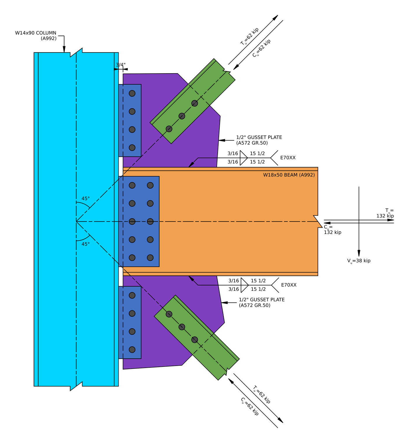
Elevation of the example connection. Both gussets are 15 1/2 in square, and each brace line runs through the work point where the beam and column centrelines meet.
Vertical brace connection design: the steps at a glance
- Distribute the brace force with the Uniform Force Method.
- Check the detailing limits at the brace bolts.
- Check the slip resistance of the brace bolts.
- Check bolt bearing and tear-out on the gusset.
- Check bolt bearing and tear-out on the brace angles.
- Check block shear of the gusset at the brace.
- Check block shear of the brace angles.
- Check the gusset in tension on its Whitmore section.
- Check the brace in tension rupture with shear lag.
- Check the gusset in compression buckling.
- Check the minimum fillet weld size at the beam.
- Check the gusset-to-beam weld.
- Check the gusset in shear yielding along the beam.
- Check the gusset in tension yielding along the beam.
- Check the beam web under the gusset.
- Check the detailing limits of the gusset-to-column single plate.
- Check the gusset-to-column bolt group.
- Check that the gusset single plate is thin enough to be ductile.
- Check bolt bearing on the gusset single plate.
- Check bolt bearing on the gusset at the column.
- Check block shear of the gusset single plate.
- Check block shear of the gusset at the column.
- Check the gusset single plate in shear.
- Check the gusset single plate in flexure.
- Check the gusset single plate in tension, with interaction.
- Check the gusset single plate in compression, with interaction.
- Check the weld size at the gusset single plate.
- Check the gusset single plate weld to the column.
- Check the column web under the gusset force.
- Check the detailing limits of the beam single plate.
- Check the beam-to-column bolt group.
- Check that the beam single plate is thin enough to be ductile.
- Check bolt bearing on the beam single plate.
- Check bolt bearing on the beam web.
- Check block shear of the beam single plate.
- Check block shear of the beam web under axial load.
- Check the beam single plate in shear.
- Check the beam single plate in flexure.
- Check the beam single plate in tension, with interaction.
- Check the beam single plate in compression, with interaction.
- Check the beam in tension rupture.
- Check the weld size at the beam single plate.
- Check the beam single plate weld to the column.
- Check the column web under the beam axial force.
Design inputs for this example
The design code is AISC 360-16 LRFD. Section properties are from the AISC Manual. The upper and lower brace connections are identical and mirror each other about the beam, and the report’s results for the two match exactly, so Steps 2 to 29 are worked once and apply to both.
| Item | Symbol | Value |
|---|---|---|
| Brace force, tension or compression (each brace) | [mathin] P [mathin] | 62 kip |
| Beam shear | [mathin] V_{u} [mathin] | 38 kip |
| Beam transfer force, tension or compression | [mathin] T_{u},\ C_{u} [mathin] | 132 kip |
| Column | W14x90, A992 | |
| Column depth / web thickness | [mathin] d_{c},\ t_{w,c} [mathin] | 14 in / 0.44 in |
| Column flange width / thickness | [mathin] b_{f,c},\ t_{f,c} [mathin] | 14.5 in / 0.71 in |
| Column kdes | [mathin] k_{des,c} [mathin] | 1.31 in |
| Beam | W18x50, A992 | |
| Beam depth / web thickness | [mathin] d_{bm},\ t_{w,bm} [mathin] | 18 in / 0.355 in |
| Beam flange width / thickness | [mathin] b_{f,bm},\ t_{f,bm} [mathin] | 7.5 in / 0.57 in |
| Beam area / kdes | [mathin] A_{bm},\ k_{des,bm} [mathin] | 14.7 in² / 0.972 in |
| Beam setback from the column face | [mathin] clr [mathin] | 0.75 in |
| Column and beam yield / tensile stress | [mathin] F_{y},\ F_{u} [mathin] | 50 ksi / 65 ksi |
| Braces (each) | 2L5x5x1/2, A36 | |
| Brace area (both angles) | [mathin] A_{br} [mathin] | 9.58 in² |
| Angle leg thickness / centroid | [mathin] t_{l,br},\ \bar{y} [mathin] | 0.5 in / 1.42 in |
| Brace angle from the support | [mathin] \theta [mathin] | 45° |
| Brace unbraced length on the gusset | [mathin] L_{b} [mathin] | 9 in |
| Brace yield / tensile stress | [mathin] F_{y,br},\ F_{u,br} [mathin] | 36 ksi / 58 ksi |
| Modulus of elasticity | [mathin] E [mathin] | 29000 ksi |
| Item | Symbol | Value |
|---|---|---|
| Gusset plates | 1/2 in, A572 Grade 50, 15.5 in x 15.5 in | |
| Gusset thickness | [mathin] t_{gp} [mathin] | 0.5 in |
| Gusset yield / tensile stress | [mathin] F_{y,gp},\ F_{u,gp} [mathin] | 50 ksi / 65 ksi |
| Bolts (all) | 1 in A490-SC, Class A surface | |
| Brace bolts: rows / spacing / lines | [mathin] n_{r},\ s_{r},\ n_{c} [mathin] | 3 / 3 in / 1 |
| Brace bolts: gage on the angle leg / end distance | [mathin] g_{a},\ L_{ev} [mathin] | 3 in / 1.5 in |
| Holes in brace / gusset | Standard (STD) / oversized (OVS) | |
| Gusset-to-beam weld | [mathin] W,\ F_{EXX} [mathin] | 3/16 in fillet both sides, E70XX, 15.5 in long |
| Gusset single plate | PL 3/8 x 3 3/4 x 12, A36 | |
| Gusset single plate bolts: rows / spacing / lines | [mathin] n_{r},\ s_{r},\ n_{c} [mathin] | 4 / 3 in / 1 |
| Holes in gusset / gusset single plate | STD / horizontal short slots (HSSL) | |
| Gusset single plate weld to column | [mathin] W [mathin] | 1/4 in fillet both sides, E70XX |
| Beam single plate | PL 1/2 x 6 3/4 x 15, A572 Grade 50 | |
| Beam single plate bolts: rows / spacing | [mathin] n_{r},\ s_{r} [mathin] | 5 / 3 in |
| Beam single plate bolts: lines / spacing | [mathin] n_{c},\ s_{c} [mathin] | 2 / 3 in |
| Horizontal edge distance, all plates | [mathin] L_{eh} [mathin] | 1.5 in |
| Holes in beam web / beam single plate | STD / HSSL | |
| Beam single plate weld to column | [mathin] W [mathin] | 5/16 in fillet both sides, E70XX |
The A36 grade on the 3/8 in gusset single plate and the angles is normal for those parts. All three interfaces use slip-critical bolts, which is required here because every interface has oversized or slotted holes (AISC 360-16 J3.2).
Step 1: Distribute the brace force with the Uniform Force Method (AISC Manual Part 13)
The Uniform Force Method picks gusset dimensions so that the forces at the gusset-to-beam and gusset-to-column interfaces carry no moment, then splits the brace force between them. Whatever horizontal force the gusset puts into the column has to come back out of the beam, so it also changes the axial force in the beam-to-column connection.
Where [mathin] e_{b} = d_{bm}/2 = 9\,in [mathin], [mathin] e_{c} = d_{c}/2 = 7\,in [mathin], [mathin] \tan\theta = 1 [mathin] and [mathin] \beta = 7.75\,in [mathin], half the gusset height on the column. The ideal centroid of the gusset-to-beam force follows from the UFM constraint:
[math] \alpha = e_{b} \tan\theta – e_{c} + \beta \tan\theta = (9\,in) \times (1) – (7\,in) + (7.75\,in) \times (1) = 9.75\,in [math]
The actual centroid of the gusset-to-beam weld is [mathin] \bar{\alpha} = 15.5/2 + 0.75 = 8.5\,in [mathin] from the column face: half the gusset length plus the setback. The distance that sets the force split is:
[math] r = \sqrt{\left( \alpha + e_{c} \right)^{2} + \left( \beta + e_{b} \right)^{2}} = \sqrt{\left( (9.75\,in) + (7\,in) \right)^{2} + \left( (7.75\,in) + (9\,in) \right)^{2}} = 23.688\,in [math]
The interface forces, with [mathin] P = 62\,kip [mathin]:
[math] H_{c} = \frac{e_{c}\, P}{r} = \frac{(7\,in) \times (62\,kip)}{(23.688\,in)} = 18.321\,kip [math]
[math] H_{b} = \frac{\alpha\, P}{r} = \frac{(9.75\,in) \times (62\,kip)}{(23.688\,in)} = 25.519\,kip [math]
The vertical force at the beam would be [mathin] e_{b} P / r = 23.556\,kip [mathin]. This report uses Special Case 2 of the method (AISC Manual Part 13, Design Guide 29 Example 5.3) and moves all of it to the gusset-to-column interface as [mathin] \Delta V_{b} = 23.556\,kip [mathin]. That way the beam-to-column connection does not have to carry the brace’s vertical force, at the cost of a moment on the gusset-to-beam interface:
[math] V_{c} = \frac{\beta\, P}{r} + \Delta V_{b} = \frac{(7.75\,in) \times (62\,kip)}{(23.688\,in)} + (23.556\,kip) = 43.841\,kip [math]
[math] V_{b} = \frac{e_{b}\, P}{r} – \Delta V_{b} = \frac{(9\,in) \times (62\,kip)}{(23.688\,in)} – (23.556\,kip) = 0\,kip [math]
[math] M_{b} = V_{b} \left| \alpha – \bar{\alpha} \right| + \Delta V_{b} \left| \alpha \right| = (0\,kip) \times \left| (9.75\,in) – (8.5\,in) \right| + (23.556\,kip) \times \left| (9.75\,in) \right| = 19.139\,kip{\cdot}ft [math]
The beam-to-column connection then carries the beam’s own forces plus the horizontal force each gusset sends straight to the column, which the beam has to bring back:
[math] C_{total} = T_{total} = C_{u} + \max\left( H_{c,upper},\, H_{c,lower} \right) = (132\,kip) + (18.321\,kip) = 150.32\,kip [math]
[math] V_{total} = V_{u} + V_{b,upper} + V_{b,lower} = (38\,kip) + (0\,kip) + (0\,kip) = 38\,kip [math]
Because the brace is at 45° and [mathin] e_{b} > e_{c} [mathin], the beam interface takes the larger share of the horizontal force, 25.519 kip of the 43.84 kip brace component.
Step 2: Detailing limits at the brace bolts (AISC 360-16 J3.3, J3.4, J3.5)
The bolt layout has to be buildable and match the assumptions behind the strength equations. Bolts that are too close tear between the holes, and edges that are too close tear out.
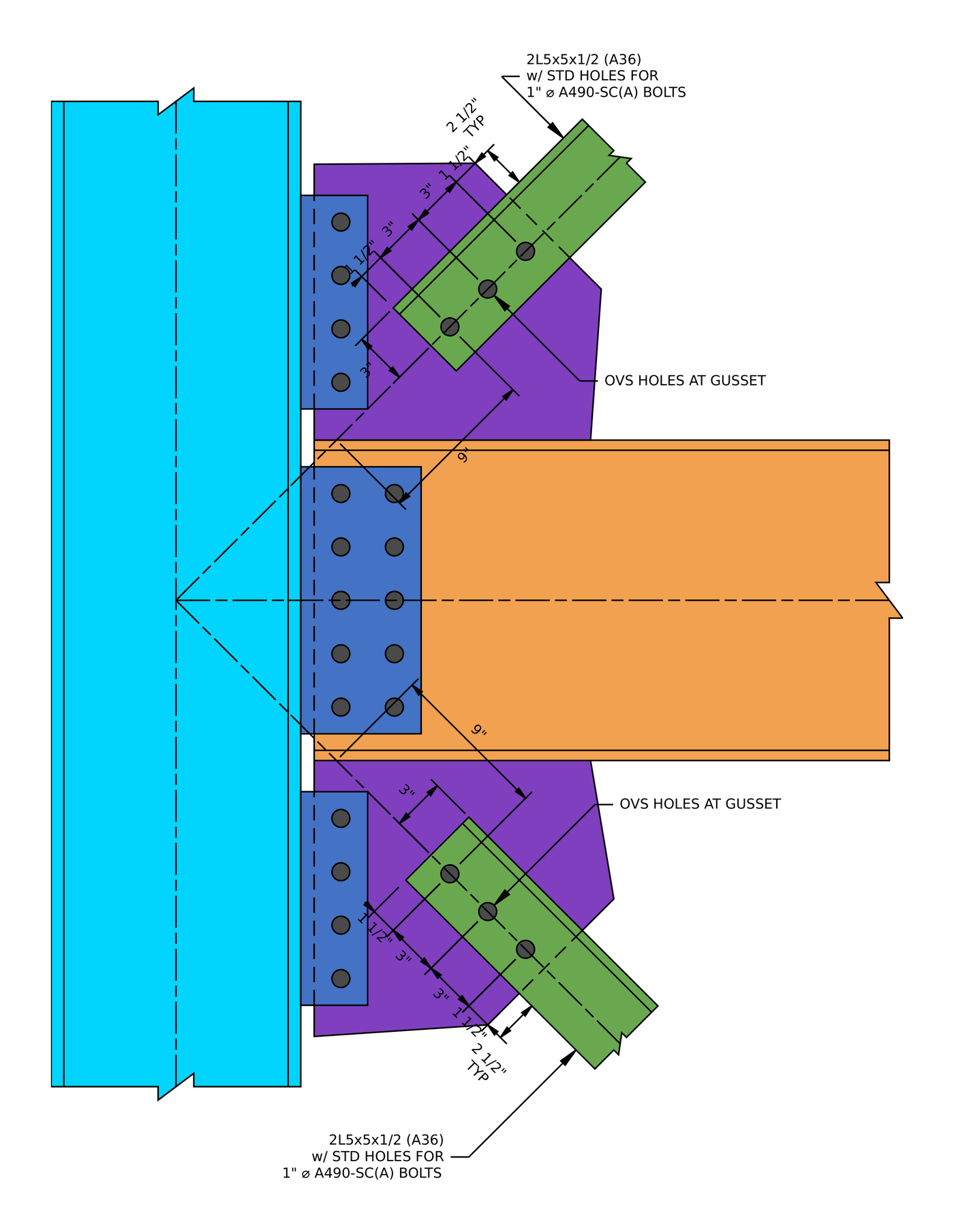
Brace connection detail. Three bolts per brace at 3 in, oversized holes in the gusset and standard holes in the angles.
For a 1 in bolt the minimum spacing is [mathin] 2\tfrac{2}{3} d_{b} = 2.667\,in [mathin] (J3.3) and the minimum edge distance is 1.25 in (Table J3.4). The gusset has oversized holes, so the Table J3.5 increment of 1/8 in raises its minimum end distance to 1.375 in.
| Detailing limit | Limit (in) | Actual (in) | DCR | Result |
|---|---|---|---|---|
| Minimum bolt gage | 2.000 | 3.000 | 0.667 | PASS |
| Minimum bolt row spacing | 2.667 | 3.000 | 0.889 | PASS |
| Maximum bolt row spacing | 6.000 | 3.000 | 0.500 | PASS |
| Gusset minimum vertical edge distance (OVS) | 1.375 | 1.500 | 0.917 | PASS |
| Brace minimum vertical edge distance | 1.250 | 1.500 | 0.833 | PASS |
| Brace minimum horizontal edge distance | 1.250 | 2.000 | 0.625 | PASS |
The horizontal edge distance on the angle is the 5 in leg less the 3 in gage, 2 in. The governing row is the gusset end distance with its oversized hole increment:
[math] DCR = \frac{d}{c} = \frac{(1.375)}{(1.5)} = 0.91667 [math]
DCR = 0.917 < 1.0, OK
Step 3: Slip resistance of the brace bolts (AISC 360-16 J3.8)
The gusset has oversized holes, which AISC 360-16 J3.2 allows only in slip-critical joints. The bolts are pretensioned, and friction between the angles and the gusset carries the brace force. The check is that the joint does not slip under the factored load.
Where [mathin] \phi = 0.85 [mathin] for oversized holes, [mathin] \mu = 0.3 [mathin] for a Class A surface, [mathin] D_{u} = 1.13 [mathin], [mathin] h_{f} = 1 [mathin] because there are no fillers, [mathin] T_{b} = 64\,kip [mathin] for a 1 in A490 bolt (Table J3.1), [mathin] N_{s} = 2 [mathin] slip planes because the gusset sits between the two angles, [mathin] n_{r} = 3 [mathin] and [mathin] n_{c} = 1 [mathin]:
[math] \phi R_{n} = \phi\, \mu\, D_{u}\, h_{f}\, T_{b}\, N_{s}\, n_{r}\, n_{c} [math]
[math] \phi R_{n} = (0.85) \times (0.3) \times (1.13) \times (1) \times (64\,kip) \times (2) \times (3) \times (1) [math]
[math] \phi R_{n} = 110.65\,kip [math]
DCR = 62 kip / 110.65 kip = 0.560 < 1.0, OK
The double angle doubles the slip strength for free: each bolt clamps two faying surfaces.
Step 4: Bolt bearing and tear-out on the gusset (AISC 360-16 J3.10)
Slip-critical bolts still have to be checked for bearing, because if the joint slips the bolts bear on the sides of their holes. The bolt nearest the gusset’s edge has the least material in front of it.
The gusset hole is oversized, [mathin] d_{h} = 1.25\,in [mathin]. Clear distances for the end bolt and between bolts:
[math] l_{c1} = L_{ev} – \frac{d_{h}}{2} = (1.5\,in) – \frac{(1.25\,in)}{2} = 0.875\,in [math]
[math] l_{c2} = s_{r} – d_{h} = (3\,in) – (1.25\,in) = 1.75\,in [math]
Where [mathin] t_{gp} = 0.5\,in [mathin], [mathin] F_{u,gp} = 65\,ksi [mathin], [mathin] n_{r} = 3 [mathin], [mathin] n_{c} = 1 [mathin], [mathin] d_{b} = 1\,in [mathin] and [mathin] \phi = 0.75 [mathin]:
[math] \phi R_{n} = \phi \left[ \min\left(1.2\, l_{c1},\, 2.4\, d_{b}\right) t_{gp} F_{u,gp}\, n_{c} + \min\left(1.2\, l_{c2},\, 2.4\, d_{b}\right) t_{gp} F_{u,gp}\, n_{c} \left( n_{r} – 1 \right) \right] [math]
[math] \phi R_{n} = (0.75) \times \left[ \min\left(1.2 \times (0.875\,in),\, 2.4 \times (1\,in)\right) \times (0.5\,in) \times (65\,ksi) \times (1) + \min\left(1.2 \times (1.75\,in),\, 2.4 \times (1\,in)\right) \times (0.5\,in) \times (65\,ksi) \times (1) \times ((3) – 1) \right] [math]
[math] \phi R_{n} = 127.97\,kip [math]
DCR = 62 kip / 127.97 kip = 0.484 < 1.0, OK
Tear-out governs every bolt, because the oversized hole cuts into the clear distance.
Step 5: Bolt bearing and tear-out on the brace (AISC 360-16 J3.10)
The same check applies to the angles. Both angle legs bear on the bolts, so the bearing thickness is twice the leg, [mathin] 2 t_{l,br} = 1\,in [mathin].
The angles have standard holes, [mathin] d_{h} = 1.125\,in [mathin]:
[math] l_{c1} = (1.5\,in) – \frac{(1.125\,in)}{2} = 0.9375\,in \qquad l_{c2} = (3\,in) – (1.125\,in) = 1.875\,in [math]
With [mathin] F_{u,br} = 58\,ksi [mathin]:
[math] \phi R_{n} = \phi \left[ \min\left(1.2\, l_{c1},\, 2.4\, d_{b}\right) 2 t_{l,br} F_{u,br}\, n_{c} + \min\left(1.2\, l_{c2},\, 2.4\, d_{b}\right) 2 t_{l,br} F_{u,br}\, n_{c} \left( n_{r} – 1 \right) \right] [math]
[math] \phi R_{n} = (0.75) \times \left[ \min\left(1.2 \times (0.9375\,in),\, 2.4 \times (1\,in)\right) \times (1\,in) \times (58\,ksi) \times (1) + \min\left(1.2 \times (1.875\,in),\, 2.4 \times (1\,in)\right) \times (1\,in) \times (58\,ksi) \times (1) \times ((3) – 1) \right] [math]
[math] \phi R_{n} = 244.69\,kip [math]
DCR = 62 kip / 244.69 kip = 0.253 < 1.0, OK
Step 6: Block shear of the gusset at the brace (AISC 360-16 J4.3)
A block of the gusset can tear out around the bolts: shear along the bolt line and tension across to the gusset’s edge. With one bolt line, this is an L-shaped block.
Where [mathin] L_{eh,gp} = 2\,in [mathin] is the edge distance on the gusset beside the bolt line, [mathin] L_{br,gp} = 9\,in [mathin] is the length of brace on the gusset, and each hole adds 1/16 in for damage (B4.3):
[math] A_{nt} = t_{gp} \left[ (n_{c}-1)\, s_{c} + L_{eh,gp} – (n_{c} – 0.5) \left( d_{h} + 0.0625\,in \right) \right] = (0.5\,in) \times \left[ 0 + (2\,in) – ((1) – 0.5) \times ((1.25\,in) + (0.0625\,in)) \right] = 0.67188\,in^{2} [math]
[math] A_{gv} = t_{gp} \left[ L_{ev} + (n_{r}-1)\, s_{r} \right] = (0.5\,in) \times \left[ (1.5\,in) + ((3)-1) \times (3\,in) \right] = 3.75\,in^{2} [math]
[math] A_{nv} = t_{gp} \left[ L_{br,gp} – L_{ev} – (n_{r} – 0.5)\left( d_{h} + 0.0625\,in \right) \right] = (0.5\,in) \times \left[ (9\,in) – (1.5\,in) – ((3) – 0.5) \times ((1.25\,in) + (0.0625\,in)) \right] = 2.1094\,in^{2} [math]
With [mathin] U_{bs} = 1 [mathin] and [mathin] \phi = 0.75 [mathin]:
[math] \phi R_{n} = \phi \left( 0.6\, F_{u} A_{nv} + U_{bs} F_{u} A_{nt} \le 0.6\, F_{y} A_{gv} + U_{bs} F_{u} A_{nt} \right) [math]
[math] \phi R_{n} = (0.75) \times \left( 0.6 \times (65\,ksi) \times (2.1094\,in^{2}) + (1) \times (65\,ksi) \times (0.67188\,in^{2}) \le 0.6 \times (50\,ksi) \times (3.75\,in^{2}) + (1) \times (65\,ksi) \times (0.67188\,in^{2}) \right) = 94.453\,kip [math]
DCR = 62 kip / 94.453 kip = 0.656 < 1.0, OK
This is the highest strength check on the brace side. Shear rupture on the net section governs over shear yielding.
Step 7: Block shear of the brace (AISC 360-16 J4.3)
The same tear-out can happen in the angle legs. Both angles act together, so the thickness is [mathin] 2 t_{l,br} = 1\,in [mathin], with standard holes [mathin] d_{h} = 1.125\,in [mathin] and the 2 in leg edge [mathin] L_{eh,br} [mathin]:
[math] A_{nt} = (1\,in) \times \left[ 0 + (2\,in) – 0.5 \times ((1.125\,in) + (0.0625\,in)) \right] = 1.4063\,in^{2} [math]
[math] A_{gv} = (1\,in) \times \left[ (1.5\,in) + 2 \times (3\,in) \right] = 7.5\,in^{2} [math]
[math] A_{nv} = (1\,in) \times \left[ (9\,in) – (1.5\,in) – 2.5 \times ((1.125\,in) + (0.0625\,in)) \right] = 4.5313\,in^{2} [math]
[math] \phi R_{n} = (0.75) \times \left( 0.6 \times (58\,ksi) \times (4.5313\,in^{2}) + (1) \times (58\,ksi) \times (1.4063\,in^{2}) \le 0.6 \times (36\,ksi) \times (7.5\,in^{2}) + (1) \times (58\,ksi) \times (1.4063\,in^{2}) \right) = 179.44\,kip [math]
DCR = 62 kip / 179.44 kip = 0.346 < 1.0, OK
Step 8: Gusset in tension on the Whitmore section (AISC 360-16 J4.1)
The brace force spreads into the gusset at about 30° on each side of the bolt line. The Whitmore section is the width of that spread at the last bolt, and the gusset has to yield and rupture on it no earlier than the brace force.
With [mathin] L_{br} = (n_{r}-1) s_{r} = 6\,in [mathin] and [mathin] W_{br} = 0 [mathin] for a single bolt line (AISC Manual Fig. 9-1):
[math] W = 2\, L_{br} \tan 30^{\circ} + W_{br} = 2 \times (6\,in) \times \tan 30^{\circ} + 0 = 6.9282\,in [math]
[math] \phi R_{n,ty} = \phi\, F_{y,gp}\, t_{gp}\, W = (0.9) \times (50\,ksi) \times (0.5\,in) \times (6.9282\,in) = 155.88\,kip [math]
[math] \phi R_{n,tr} = \phi\, F_{u,gp}\, t_{gp} \left[ W – n_{c}\left( d_{h} + 0.0625\,in \right) \right] = (0.75) \times (65\,ksi) \times (0.5\,in) \times \left[ (6.9282\,in) – (1) \times ((1.25\,in) + (0.0625\,in)) \right] = 136.88\,kip [math]
DCR = 62 kip / 136.88 kip = 0.453 < 1.0, OK
Step 9: Brace in tension rupture with shear lag (AISC 360-16 D3, J4.1)
Only one leg of each angle is bolted, so the stress in the outstanding legs has to lag in through the connected legs. The shear lag factor U reduces the net area to account for this.
With [mathin] \bar{y} = 1.42\,in [mathin] and connection length [mathin] (n_{r}-1) s_{r} = 6\,in [mathin] (Table D3.1, Case 2):
[math] U = 1 – \frac{\bar{y}}{(n_{r}-1)\, s_{r}} = 1 – \frac{(1.42\,in)}{((3)-1) \times (3\,in)} = 0.76343 [math]
[math] \phi R_{n} = \phi\, F_{u,br}\, U \left[ A_{br} – n_{c} \left( d_{h} + 0.0625\,in \right) 2 t_{l,br} \right] = (0.75) \times (58\,ksi) \times (0.76343) \times \left[ (9.58\,in^{2}) – (1) \times ((1.125\,in) + (0.0625\,in)) \times (1\,in) \right] = 278.71\,kip [math]
DCR = 62 kip / 278.71 kip = 0.222 < 1.0, OK
Step 10: Gusset in compression buckling (AISC 360-16 J4.4, E3)
When the brace pushes, the Whitmore strip of gusset between the last bolt and the gusset’s supported edges acts as a short column.
With [mathin] K = 1.2 [mathin], [mathin] L = 9\,in [mathin] and [mathin] r = t_{gp}/\sqrt{12} [mathin], [mathin] KL/r = 74.825 [mathin], which is above 25, so Chapter E applies. It is also below [mathin] 4.71\sqrt{E/F_{y}} = 113.43 [mathin], so Eq. E3-2 applies:
[math] F_{e} = \frac{\pi^{2} E}{\left( KL/r \right)^{2}} = \frac{\pi^{2} \times (29000\,ksi)}{(74.825)^{2}} = 51.122\,ksi [math]
[math] F_{cr} = 0.658^{\frac{F_{y}}{F_{e}}} F_{y} = 0.658^{\frac{(50\,ksi)}{(51.122\,ksi)}} \times (50\,ksi) = 33.204\,ksi [math]
[math] \phi R_{n} = \phi\, F_{cr}\, t_{gp}\, W = (0.9) \times (33.204\,ksi) \times (0.5\,in) \times (6.9282\,in) = 103.52\,kip [math]
DCR = 62 kip / 103.52 kip = 0.599 < 1.0, OK
Buckling cuts the gusset’s compression strength to about two thirds of its yield strength in tension. A 9 in unbraced length is about the most a 1/2 in gusset can take at this load.
Step 11: Minimum fillet weld size at the beam (AISC 360-16 J2.2b)
A fillet weld that is too small for the parts it joins can crack as it cools. Table J2.4 sets the minimum by the thinner part, here the 1/2 in gusset, so the minimum is 3/16 in.
[math] DCR = \frac{d}{c} = \frac{(0.188)}{(0.188)} = 1 [math]
DCR = 1.000, OK
A ratio of 1.000 here means the 3/16 in weld is exactly the smallest size allowed. Its strength is checked next.
Step 12: Gusset-to-beam weld (AISC 360-16 J2.4, AISC Design Guide 29)
The weld carries the horizontal force [mathin] H_{b} [mathin] along its length, plus the moment [mathin] M_{b} [mathin] from Step 1 as a varying normal force. The check uses the peak force per inch at the most loaded end.
Base metal limit on weld size (AISC Manual Eq. 9-2)
The weld cannot be stronger than the metal it is fused to. The gusset is welded on both faces, so it gets half its thickness per weld:
[math] D_{max} = \frac{t_{f,bm} F_{u,bm} \le 0.5\, t_{gp} F_{u,gp}}{3.09\,kip/in \times 1} = \frac{(0.57\,in) \times (65\,ksi) \le (0.25\,in) \times (65\,ksi)}{(3.09\,kip/in) \times (1)} = 5.2589 [math]
Effective weld length
[math] L_{w} = 2 \left[ L_{gp} – 2 W \right] = 2 \times \left[ (15.5\,in) – 2 \times (0.1875\,in) \right] = 30.25\,in [math]
Forces on the weld
The moment becomes a normal force using the plastic section of two weld lines, [mathin] L_{w}^{2}/8 [mathin]. With [mathin] V_{b} = 0 [mathin]:
[math] V_{b,total} = \frac{8\, M_{b}}{L_{w}} + V_{b} = \frac{8 \times (19.139\,kip{\cdot}ft)}{(30.25\,in)} + (0\,kip) = 60.74\,kip [math]
[math] R = \sqrt{V_{b,total}^{2} + H_{b}^{2}} = \sqrt{(60.74\,kip)^{2} + (25.519\,kip)^{2}} = 65.883\,kip \qquad \theta = \tan^{-1}\left| \frac{60.74}{25.519} \right| = 67.211^{\circ} [math]
At the other end of the weld the normal force is [mathin] |V_{b} – 8 M_{b}/L_{w}| = 60.74\,kip [mathin], so [mathin] R_{min} = 65.883\,kip [mathin] too. AISC Manual Part 13 applies a 1.25 weld ductility factor to the average of the two ends:
[math] R_{w} = \max\left( R,\, 1.25\, \frac{R + R_{min}}{2} \right) = \max\left( (65.883\,kip),\, 1.25 \times \frac{(65.883\,kip) + (65.883\,kip)}{2} \right) = 82.354\,kip [math]
Because [mathin] V_{b} = 0 [mathin], the moment loads both ends equally (one in tension, one in compression), and [mathin] R_{w} [mathin] is simply [mathin] 1.25 R [mathin].
Weld strength (Eq. J2-4)
[math] \phi R_{n} = \phi\, 0.6\, F_{EXX} \frac{\sqrt{2}}{2} \left( W \le \frac{D_{max}}{16} \right) \left[ 1 + 0.5 \left( \sin\theta \right)^{1.5} \right] L_{w} [math]
[math] \phi R_{n} = (0.75) \times 0.6 \times (70\,ksi) \times \frac{\sqrt{2}}{2} \times \left( (0.1875\,in) \le \frac{(5.2589)}{(16)} \right) \times \left[ 1 + 0.5 \times (\sin(67.211^{\circ}))^{1.5} \right] \times (30.25\,in) = 182.25\,kip [math]
DCR = 82.354 kip / 182.25 kip = 0.452 < 1.0, OK
Nearly all of the weld force comes from the Special Case 2 moment. Without it, the weld would only see the 25.519 kip horizontal force.
Step 13: Gusset in shear yielding along the beam (AISC 360-16 J4.2)
The horizontal force [mathin] H_{b} [mathin] shears the gusset along its welded edge. With [mathin] A_{gv} = 15.5 \times 0.5 = 7.75\,in^{2} [mathin] and [mathin] \phi = 1 [mathin] (Design Guide 29 Example 5.3):
[math] \phi R_{n} = \phi\, 0.6\, F_{y,gp} A_{gv} = (1) \times 0.6 \times (50\,ksi) \times (7.75\,in^{2}) = 232.5\,kip [math]
DCR = 25.519 kip / 232.5 kip = 0.110 < 1.0, OK
Step 14: Gusset in tension yielding along the beam (AISC 360-16 J4.1)
The moment puts one end of the gusset’s welded edge in tension. Following Design Guide 29 Example 5.3, the normal force and the moment are added as stresses on the edge and turned back into an equivalent force over the full 15.5 in length:
[math] N_{e} = \left| V_{b} \right| + \frac{4 \left| M_{b} \right|}{L_{gp}} = (0\,kip) + \frac{4 \times (19.139\,kip{\cdot}ft)}{(15.5\,in)} = 59.27\,kip [math]
[math] \phi R_{n} = \phi\, F_{y,gp}\, t_{gp}\, L_{gp} = (0.9) \times (50\,ksi) \times (0.5\,in) \times (15.5\,in) = 348.75\,kip [math]
DCR = 59.27 kip / 348.75 kip = 0.170 < 1.0, OK
Step 15: Beam web under the gusset (AISC 360-16 J10.3, J10.2)
The compression half of the gusset moment pushes on the beam flange next to the column, so the beam web there can cripple or yield locally. The gusset sits at the end of the beam, so the near-end forms of the equations apply.
The report applies half the peak normal force, [mathin] 60.74/2 = 30.37\,kip [mathin], over half the gusset length, [mathin] l_{b} = 7.75\,in [mathin]. That models the compression side of the moment couple. With [mathin] \phi = 0.75 [mathin], [mathin] l_{b}/d = 0.43 > 0.2 [mathin] and [mathin] Q_{f} = 1 [mathin]:
[math] \phi R_{n,wlc} = \phi\, 0.4\, t_{w}^{2} \left[ 1 + \left( \frac{4 l_{b}}{d} – 0.2 \right) \left( \frac{t_{w}}{t_{f}} \right)^{1.5} \right] \sqrt{\frac{E\, F_{y}\, t_{f}}{t_{w}}}\, Q_{f} [math]
[math] \phi R_{n,wlc} = (0.75) \times 0.4 \times (0.355\,in)^{2} \times \left[ 1 + \left( \frac{4 \times (7.75\,in)}{(18\,in)} – 0.2 \right) \times \left( \frac{(0.355\,in)}{(0.57\,in)} \right)^{1.5} \right] \times \sqrt{\frac{(29000\,ksi) \times (50\,ksi) \times (0.57\,in)}{(0.355\,in)}} \times (1) = 100.85\,kip [math]
Web local yielding near the member end (Eq. J10-3), with [mathin] \phi = 1 [mathin]:
[math] \phi R_{n,wly} = \phi\, F_{y}\, t_{w} \left( 2.5\, k_{des} + l_{b} \right) = (1) \times (50\,ksi) \times (0.355\,in) \times \left( 2.5 \times (0.972\,in) + (7.75\,in) \right) = 180.69\,kip [math]
DCR = 30.37 kip / 100.85 kip = 0.301 < 1.0, OK
The report labels the crippling equation J10-4, but the numbers it substitutes are the near-end form with 0.4 and (4lb/d − 0.2), which is Eq. J10-5b. That is the right form for a force this close to the beam end.
Step 16: Detailing limits of the gusset single plate (AISC 360-16 J3.3, J3.4, J3.5)
The gusset bolts to a 3/8 in plate welded to the column flange. The plate has horizontal short slots, which add 1/8 in to the minimum edge distance across the slot (Table J3.5).
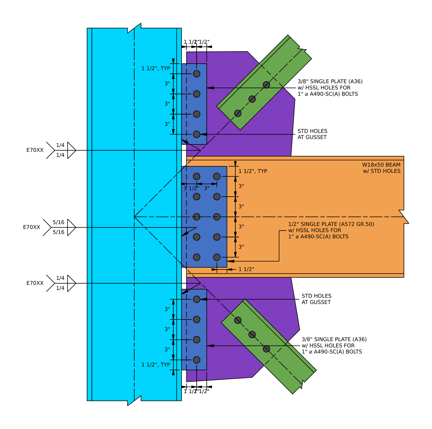
Single plate detail. The gusset plates take four bolts in one line, and the beam plate takes two lines of five. All three plates have horizontal short slots.
| Detailing limit | Limit (in) | Actual (in) | DCR | Result |
|---|---|---|---|---|
| Minimum bolt row spacing | 2.667 | 3.000 | 0.889 | PASS |
| Maximum bolt row spacing | 6.000 | 3.000 | 0.500 | PASS |
| Plate minimum vertical edge distance | 1.250 | 1.500 | 0.833 | PASS |
| Plate minimum horizontal edge distance (HSSL) | 1.375 | 1.500 | 0.917 | PASS |
| Gusset minimum horizontal edge distance | 1.250 | 1.500 | 0.833 | PASS |
| Minimum plate depth | 7.750 | 12.000 | 0.646 | PASS |
The minimum plate depth is half the 15.5 in gusset edge on the column, so the plate supports at least half the gusset.
DCR = 1.375 / 1.5 = 0.917 < 1.0, OK
Step 17: Gusset-to-column bolt group (AISC 360-16 J3.8, AISC Manual Part 7)
The four bolts carry [mathin] V_{c} [mathin] and [mathin] H_{c} [mathin] together, at an eccentricity from the weld line. The instantaneous center of rotation method gives the coefficient C: the number of bolts the eccentric group is worth.
The resultant and its angle from vertical:
[math] R = \sqrt{V_{c}^{2} + H_{c}^{2}} = \sqrt{(43.841\,kip)^{2} + (18.321\,kip)^{2}} = 47.515\,kip \qquad \theta = \tan^{-1}\left( \frac{18.321}{43.841} \right) = 22.681^{\circ} [math]
The eccentricity is the distance from the weld to the bolt line, [mathin] e = 2.25\,in [mathin]. For bolts at (0, 0), (0, 3), (0, 6) and (0, 9), the iteration puts the instantaneous center at [mathin] x_{ic} = -4.0517\,in [mathin], [mathin] y_{ic} = 6.7655\,in [mathin], which gives [mathin] C = 3.14 [mathin] and the moment coefficient [mathin] C’ = 11.256\,in [mathin]. Each bolt is slip-critical, with [mathin] N_{s} = 1 [mathin]:
[math] \phi R_{n} = \phi\, \mu\, D_{u}\, h_{f}\, T_{b}\, N_{s}\, C = (0.85) \times (0.3) \times (1.13) \times (1) \times (64\,kip) \times (1) \times (3.14) = 57.907\,kip [math]
DCR = 47.515 kip / 57.907 kip = 0.821 < 1.0, OK
The slots are horizontal and the resultant leans 22.7° toward them, so the report keeps φ = 0.85 for slotted holes. Bolt slip is the highest check on the gusset side.
Step 18: Ductility of the gusset single plate (AISC Manual Part 10)
A single plate has to yield in flexure before the bolts shear off, so the plate cannot be too thick. AISC Manual Part 10 (Eq. 10-3 and 10-4) gives the maximum thickness from the moment the bolt group can carry.
With [mathin] F_{nv} = 68\,ksi [mathin], [mathin] d_{b} = 1\,in [mathin], [mathin] C’ = 11.256\,in [mathin], [mathin] F_{y} = 36\,ksi [mathin] and [mathin] h = 12\,in [mathin]:
[math] M_{max} = \frac{F_{nv}}{0.90} \frac{\pi d_{b}^{2}}{4} C’ = \frac{(68\,ksi)}{0.90} \times \frac{\pi \times (1\,in)^{2}}{4} \times (11.256\,in) = 55.664\,kip{\cdot}ft [math]
[math] t_{max} = \frac{6\, M_{max}}{F_{y}\, h^{2}} = \frac{6 \times (55.664\,kip{\cdot}ft)}{(36\,ksi) \times (12\,in)^{2}} = 0.77311\,in [math]
DCR = 0.375 in / 0.77311 in = 0.485 < 1.0, OK
Step 19: Bolt bearing on the gusset single plate (AISC 360-16 J3.10)
The plate is checked for bearing and tear-out in each direction of load separately, then for both together. Each strength is the average per bolt multiplied by C, so it matches the bolt group’s capacity.
Vertical (shear) direction
The vertical hole size is the standard 1.125 in, so [mathin] l_{c1} = 0.9375\,in [mathin] and [mathin] l_{c2} = 1.875\,in [mathin]. With [mathin] t = 0.375\,in [mathin], [mathin] F_{u} = 58\,ksi [mathin] and [mathin] n_{r} = 4 [mathin]:
[math] \phi R_{n,v} = \phi \left[ \min\left(1.2\, l_{c1},\, 2.4\, d_{b}\right) t F_{u} + \min\left(1.2\, l_{c2},\, 2.4\, d_{b}\right) t F_{u} \left( n_{r} – 1 \right) \right] \frac{C}{n_{r}} [math]
[math] \phi R_{n,v} = (0.75) \times \left[ \min\left(1.125,\, 2.4\right) \times (0.375\,in) \times (58\,ksi) + \min\left(2.25,\, 2.4\right) \times (0.375\,in) \times (58\,ksi) \times ((4) – 1) \right] \times \frac{(3.14)}{(4)} = 100.84\,kip [math]
DCR = 43.841 kip / 100.84 kip = 0.435 < 1.0, OK
Horizontal (axial) direction
Across the slot the hole is 1.3125 in long, so [mathin] l_{c1} = 1.5 – 1.3125/2 = 0.84375\,in [mathin]. There is one bolt line, so the inner-bolt term is multiplied by [mathin] (n_{c} – 1) = 0 [mathin] and its negative [mathin] l_{c2} = -1.3125\,in [mathin] has no effect:
[math] \phi R_{n,a} = \phi \left[ \min\left(1.2\, l_{c1},\, 2.4\, d_{b}\right) t F_{u} + \min\left(1.2\, l_{c2},\, 2.4\, d_{b}\right) t F_{u} \left( n_{c} – 1 \right) \right] \frac{C}{n_{c}} [math]
[math] \phi R_{n,a} = (0.75) \times \left[ \min\left(1.0125,\, 2.4\right) \times (0.375\,in) \times (58\,ksi) + 0 \right] \times \frac{(3.14)}{(1)} = 51.862\,kip [math]
DCR = 18.321 kip / 51.862 kip = 0.353 < 1.0, OK
Interaction
[math] \left( \frac{V_{c}}{\phi R_{n,v}} \right)^{2} + \left( \frac{H_{c}}{\phi R_{n,a}} \right)^{2} = \left( \frac{(43.841\,kip)}{(100.84\,kip)} \right)^{2} + \left( \frac{(18.321\,kip)}{(51.862\,kip)} \right)^{2} = 0.31381 [math]
DCR = 0.314 < 1.0, OK
Step 20: Bolt bearing on the gusset at the column (AISC 360-16 J3.10)
The same three checks apply to the 1/2 in gusset, which has standard holes.
Vertical (shear) direction
The 12 in plate is centred on the 15.5 in gusset edge, so the gusset’s end distance is [mathin] L_{ev} = (15.5 – 12)/2 + 1.5 = 3.25\,in [mathin] and [mathin] l_{c1} = 2.6875\,in [mathin]. With [mathin] t = 0.5\,in [mathin] and [mathin] F_{u} = 65\,ksi [mathin]:
[math] \phi R_{n,v} = (0.75) \times \left[ \min\left(3.225,\, 2.4\right) \times (0.5\,in) \times (65\,ksi) + \min\left(2.25,\, 2.4\right) \times (0.5\,in) \times (65\,ksi) \times ((4) – 1) \right] \times \frac{(3.14)}{(4)} = 175.08\,kip [math]
DCR = 43.841 kip / 175.08 kip = 0.250 < 1.0, OK
Horizontal (axial) direction
With the 1.5 in edge and the standard hole, [mathin] l_{c1} = 0.9375\,in [mathin]:
[math] \phi R_{n,a} = (0.75) \times \left[ \min\left(1.125,\, 2.4\right) \times (0.5\,in) \times (65\,ksi) + 0 \right] \times \frac{(3.14)}{(1)} = 86.105\,kip [math]
DCR = 18.321 kip / 86.105 kip = 0.213 < 1.0, OK
Interaction
[math] \left( \frac{(43.841\,kip)}{(175.08\,kip)} \right)^{2} + \left( \frac{(18.321\,kip)}{(86.105\,kip)} \right)^{2} = 0.10798 [math]
DCR = 0.108 < 1.0, OK
Step 21: Block shear of the gusset single plate (AISC 360-16 J4.3)
A block can tear out of the plate under the vertical force, under the horizontal force, or under both. The vertical case is an L-shaped block down the bolt line. The horizontal case has two shapes, L and U, and the weaker governs.
Vertical (shear) direction
The tension leg crosses half a slotted hole, [mathin] d_{h} = 1.3125\,in [mathin]:
[math] A_{nt} = (0.375\,in) \times \left[ (1.5\,in) – 0.5 \times ((1.3125\,in) + (0.0625\,in)) \right] = 0.30469\,in^{2} [math]
[math] A_{gv} = (0.375\,in) \times \left[ (1.5\,in) + 3 \times (3\,in) \right] = 3.9375\,in^{2} [math]
[math] A_{nv} = t \left[ h_{sp} – L_{ev} – (n_{r} – 0.5)\left( d_{h} + 0.0625\,in \right) \right] = (0.375\,in) \times \left[ (12\,in) – (1.5\,in) – 3.5 \times ((1.125\,in) + (0.0625\,in)) \right] = 2.3789\,in^{2} [math]
[math] \phi R_{n} = (0.75) \times \left( 0.6 \times (58\,ksi) \times (2.3789\,in^{2}) + (1) \times (58\,ksi) \times (0.30469\,in^{2}) \le 0.6 \times (36\,ksi) \times (3.9375\,in^{2}) + (1) \times (58\,ksi) \times (0.30469\,in^{2}) \right) = 75.343\,kip [math]
DCR = 43.841 kip / 75.343 kip = 0.582 < 1.0, OK
Horizontal (axial) direction
The L pattern tears in tension along the bolt line and shears across the top. The shear leg runs from the bolt to the unbraced end of the plate, [mathin] b_{sp} – L_{b,sp} = 3.75 – 2.25 = 1.5\,in [mathin]:
[math] A_{nt} = (0.375\,in) \times \left[ 3 \times (3\,in) + (1.5\,in) – 3.5 \times (1.1875\,in) \right] = 2.3789\,in^{2} \quad A_{gv} = 0.5625\,in^{2} \quad A_{nv} = 0.30469\,in^{2} [math]
[math] \phi R_{n,L} = (0.75) \times \left( 0.6 \times (58\,ksi) \times (0.30469\,in^{2}) + (1) \times (58\,ksi) \times (2.3789\,in^{2}) \le 0.6 \times (36\,ksi) \times (0.5625\,in^{2}) + (1) \times (58\,ksi) \times (2.3789\,in^{2}) \right) = 111.43\,kip [math]
The U pattern tears in tension between the outer bolts and shears out at the top and bottom:
[math] A_{nt} = (0.375\,in) \times \left[ 3 \times (3\,in) – 3 \times (1.1875\,in) \right] = 2.0391\,in^{2} \quad A_{gv} = 2 \times (0.375\,in) \times (1.5\,in) = 1.125\,in^{2} \quad A_{nv} = 0.60938\,in^{2} [math]
[math] \phi R_{n,U} = (0.75) \times \left( 0.6 \times (58\,ksi) \times (0.60938\,in^{2}) + (1) \times (58\,ksi) \times (2.0391\,in^{2}) \le 0.6 \times (36\,ksi) \times (1.125\,in^{2}) + (1) \times (58\,ksi) \times (2.0391\,in^{2}) \right) = 104.6\,kip [math]
DCR = 18.321 kip / 104.6 kip = 0.175 < 1.0, OK
Interaction
[math] \left( \frac{(43.841\,kip)}{(75.343\,kip)} \right)^{2} + \left( \frac{(18.321\,kip)}{(104.6\,kip)} \right)^{2} = 0.36926 [math]
DCR = 0.369 < 1.0, OK
Step 22: Block shear of the gusset at the column (AISC 360-16 J4.3)
The same patterns apply to the gusset, with its 3.25 in end distance.
Vertical (shear) direction
[math] A_{nt} = (0.5\,in) \times \left[ (1.5\,in) – 0.5 \times ((1.3125\,in) + (0.0625\,in)) \right] = 0.40625\,in^{2} [math]
[math] A_{gv} = (0.5\,in) \times \left[ (3.25\,in) + 3 \times (3\,in) \right] = 6.125\,in^{2} \qquad A_{nv} = (0.5\,in) \times \left[ (15.5\,in) – (3.25\,in) – 3.5 \times (1.1875\,in) \right] = 4.0469\,in^{2} [math]
[math] \phi R_{n} = (0.75) \times \left( 0.6 \times (65\,ksi) \times (4.0469\,in^{2}) + (1) \times (65\,ksi) \times (0.40625\,in^{2}) \le 0.6 \times (50\,ksi) \times (6.125\,in^{2}) + (1) \times (65\,ksi) \times (0.40625\,in^{2}) \right) = 138.18\,kip [math]
DCR = 43.841 kip / 138.18 kip = 0.317 < 1.0, OK
The tension area uses the plate’s 1.3125 in slot length rather than the gusset’s 1.125 in standard hole. That removes a little more area than the gusset actually loses, so the result is slightly conservative.
Horizontal (axial) direction
[math] L:\ A_{nt} = 4.0469\,in^{2},\ A_{gv} = 0.75\,in^{2},\ A_{nv} = 0.40625\,in^{2} \Rightarrow \phi R_{n,L} = 209.17\,kip [math]
[math] U:\ A_{nt} = (0.5\,in) \times \left[ 9\,in – 3 \times (1.1875\,in) \right] = 2.7188\,in^{2},\ A_{gv} = 1.5\,in^{2},\ A_{nv} = 0.8125\,in^{2} \Rightarrow \phi R_{n,U} = 156.3\,kip [math]
DCR = 18.321 kip / 156.3 kip = 0.117 < 1.0, OK
Interaction
[math] \left( \frac{(43.841\,kip)}{(138.18\,kip)} \right)^{2} + \left( \frac{(18.321\,kip)}{(156.3\,kip)} \right)^{2} = 0.11441 [math]
DCR = 0.114 < 1.0, OK
Step 23: Gusset single plate in shear (AISC 360-16 J4.2)
The plate carries [mathin] V_{c} [mathin] as shear over its 12 in depth. It is checked for yielding on the gross section and rupture through the bolt holes.
[math] \phi R_{n,sy} = \phi\, 0.6\, F_{y} A_{gv} = (1) \times 0.6 \times (36\,ksi) \times (4.5\,in^{2}) = 97.2\,kip [math]
[math] A_{nv} = t \left[ h_{sp} – n_{r} \left( d_{h} + 0.0625\,in \right) \right] = (0.375\,in) \times \left[ (12\,in) – (4) \times (1.1875\,in) \right] = 2.7188\,in^{2} [math]
[math] \phi R_{n,sr} = \phi\, 0.6\, F_{u} A_{nv} = (0.75) \times 0.6 \times (58\,ksi) \times (2.7188\,in^{2}) = 70.959\,kip [math]
DCR = 43.841 kip / 70.959 kip = 0.618 < 1.0, OK
Step 24: Gusset single plate in flexure (AISC Manual Part 9, AISC 360-16 F11)
The vertical force acts at the bolt line, 2.25 in from the weld, so the plate bends. The report treats the plate like a double coped beam: a rectangular section that can buckle laterally over its unbraced length [mathin] L_{b,sp} = 2.25\,in [mathin].
The slenderness ratio [mathin] L_{b} d / t^{2} = 2.25 \times 12 / 0.375^{2} = 192 [mathin] falls between [mathin] 0.08E/F_{y} = 64.444 [mathin] and [mathin] 1.9E/F_{y} = 1530.6 [mathin], so Eq. F11-2 applies. With [mathin] Z = 13.5\,in^{3} [mathin], [mathin] S = 9\,in^{3} [mathin] and the cope depth taken as zero (AISC Manual Eq. 9-15):
[math] C_{b} = \left[ 3 + \ln\left( \frac{L_{b,sp}}{h_{sp}} \right) \right] \left( 1 – \frac{d_{c,sp}}{h_{sp}} \right) \ge 1.84 = \left[ 3 + \ln\left( \frac{(2.25\,in)}{(12\,in)} \right) \right] \times (1 – 0) \ge 1.84 = 1.84 [math]
[math] \phi M_{n} = \phi \left[ C_{b} \left[ 1.52 – 0.274 \left( \frac{L_{b} d}{t^{2}} \right) \left( \frac{F_{y}}{E} \right) \right] F_{y} S \le F_{y} Z \right] = (0.9) \times \left[ (1.84) \times \left[ 1.52 – 0.274 \times (192) \times \frac{(36\,ksi)}{(29000\,ksi)} \right] \times (36\,ksi) \times (9\,in^{3}) \le (36\,ksi) \times (13.5\,in^{3}) \right] = 36.45\,kip{\cdot}ft [math]
[math] \phi V_{n,y} = \frac{\phi M_{n}}{L_{b,sp}} = \frac{(36.45\,kip{\cdot}ft)}{(2.25\,in)} = 194.4\,kip [math]
Flexural rupture uses the net plastic modulus through the holes (AISC Manual Table 15-3):
[math] Z_{net} = \frac{t\, h^{2}}{4} – t \left( d_{h} + 0.0625\,in \right) s_{r} \left\lfloor \frac{n_{r}^{2}}{4} \right\rfloor – \left[ n_{r}\ \text{odd} \right] \frac{t \left( d_{h} + 0.0625\,in \right)^{2}}{4} = 8.1563\,in^{3} [math]
[math] \phi M_{n} = \phi\, F_{u}\, Z_{net} = (0.75) \times (58\,ksi) \times (8.1563\,in^{3}) = 29.566\,kip{\cdot}ft \qquad \phi V_{n,r} = \frac{(29.566\,kip{\cdot}ft)}{(2.25\,in)} = 157.69\,kip [math]
DCR = 43.841 kip / 157.69 kip = 0.278 < 1.0, OK
The plate is short and deep, so lateral-torsional buckling does not reduce it. The F11-2 value is capped at the plastic moment [mathin] F_{y} Z [mathin].
Step 25: Gusset single plate in tension, with interaction (AISC 360-16 J4.1, H1)
When the brace pulls, [mathin] H_{c} [mathin] puts the plate in tension.
[math] \phi R_{n,ty} = (0.9) \times (36\,ksi) \times (0.375\,in) \times (12\,in) = 145.8\,kip [math]
[math] \phi R_{n,tr} = (0.75) \times (58\,ksi) \times (0.375\,in) \times \left[ (12\,in) – (4) \times (1.1875\,in) \right] = 118.27\,kip [math]
DCR = 18.321 kip / 118.27 kip = 0.155 < 1.0, OK
The plate carries tension, bending and shear at the same time. Since the axial ratio is below 0.2, the report uses the AISC H1-1b form for axial plus flexure, then adds the squared shear ratio:
[math] \left( \frac{H_{c}}{2\, \phi R_{n}} + \frac{V_{c}}{\phi V_{n}} \right)^{2} + \left( \frac{V_{c}}{\phi R_{n,v}} \right)^{2} = \left( \frac{(18.321\,kip)}{2 \times (118.27\,kip)} + \frac{(43.841\,kip)}{(194.4\,kip)} \right)^{2} + \left( \frac{(43.841\,kip)}{(70.959\,kip)} \right)^{2} = 0.47351 [math]
DCR = 0.474 < 1.0, OK
The flexure term uses the 194.4 kip from flexural yielding, not the 157.69 kip from rupture that governed Step 24.
Step 26: Gusset single plate in compression, with interaction (AISC 360-16 J4.4, H1)
When the brace pushes, the plate is in compression. With [mathin] K = 1.2 [mathin] and [mathin] L = 2.25\,in [mathin], [mathin] KL/r = 24.942 \le 25 [mathin], so it does not buckle and Eq. J4-6 applies:
[math] \phi R_{n} = \phi\, F_{y}\, t\, h_{sp} = (0.9) \times (36\,ksi) \times (0.375\,in) \times (12\,in) = 145.8\,kip [math]
DCR = 18.321 kip / 145.8 kip = 0.126 < 1.0, OK
[math] \left( \frac{(18.321\,kip)}{2 \times (145.8\,kip)} + \frac{(43.841\,kip)}{(194.4\,kip)} \right)^{2} + \left( \frac{(43.841\,kip)}{(70.959\,kip)} \right)^{2} = 0.46486 [math]
DCR = 0.465 < 1.0, OK
Step 27: Weld size at the gusset single plate (AISC Manual Part 10)
Two checks on weld size. The weld has to fit in the 0.75 in setback, and it has to be strong enough to develop the plate, so that the plate yields before the weld breaks. AISC Manual page 10-87 sets the second at 5/8 of the plate thickness:
[math] DCR_{clr} = \frac{(0.25)}{(0.75)} = 0.333 \qquad W_{duc} = \frac{5}{8}\, t_{sp} = \frac{5}{8} \times (0.375\,in) = 0.23438\,in [math]
DCR = 0.23438 in / 0.25 in = 0.938 < 1.0, OK
Step 28: Gusset single plate weld to the column (AISC 360-16 J2.4)
The plate is welded to the column flange on both faces. The weld carries the same resultant as the bolts, 47.515 kip at 22.681° from its axis.
[math] D_{max} = \frac{\frac{t_{sp}}{2} F_{u,sp} \le t_{f,c} F_{u,c}}{3.09\,kip/in} = \frac{(0.1875\,in) \times (58\,ksi) \le (0.71\,in) \times (65\,ksi)}{(3.09\,kip/in) \times (1)} = 3.5194 [math]
[math] L_{w} = 2 \left[ h_{sp} – 2W \right] = 2 \times \left[ (12\,in) – 2 \times (0.25\,in) \right] = 23\,in [math]
[math] \phi R_{n} = (0.75) \times 0.6 \times (70\,ksi) \times \frac{\sqrt{2}}{2} \times \left( (0.25\,in) \le \frac{(3.5194)}{(16)} \right) \times \left[ 1 + 0.5 \times (\sin(22.681^{\circ}))^{1.5} \right] \times (23\,in) = 126.18\,kip [math]
DCR = 47.515 kip / 126.18 kip = 0.377 < 1.0, OK
The 3/8 in A36 plate limits the weld here: [mathin] 3.5194/16 = 0.22\,in [mathin], so only 0.22 in of the 1/4 in weld counts. A bigger weld would add nothing without a thicker plate.
Step 29: Column web under the gusset force (AISC 360-16 J10.3, J10.2)
[mathin] H_{c} [mathin] pushes or pulls on the column flange over the 12 in plate. With [mathin] l_{b} = 12\,in [mathin]:
[math] \phi R_{n,wlc} = (0.75) \times 0.8 \times (0.44\,in)^{2} \times \left[ 1 + 3 \times \left( \frac{(12\,in)}{(14\,in)} \right) \times \left( \frac{(0.44\,in)}{(0.71\,in)} \right)^{1.5} \right] \times \sqrt{\frac{(29000\,ksi) \times (50\,ksi) \times (0.71\,in)}{(0.44\,in)}} \times (1) = 400.58\,kip [math]
[math] \phi R_{n,wly} = (1) \times (50\,ksi) \times (0.44\,in) \times \left( 5 \times (1.31\,in) + (12\,in) \right) = 408.1\,kip [math]
DCR = 18.321 kip / 400.58 kip = 0.046 < 1.0, OK
Step 30: Detailing limits of the beam single plate (AISC 360-16 J3.3, J3.4, J3.5)
The beam connection is a 1/2 in single plate with two bolt lines of five, welded to the column flange. The plate has horizontal short slots, and the beam web has standard holes. Its layout is in the single plate detail under Step 16.
| Detailing limit | Limit (in) | Actual (in) | DCR | Result |
|---|---|---|---|---|
| Minimum bolt row spacing | 2.667 | 3.000 | 0.889 | PASS |
| Maximum bolt row spacing | 6.000 | 3.000 | 0.500 | PASS |
| Minimum bolt column spacing | 2.667 | 3.000 | 0.889 | PASS |
| Maximum bolt column spacing | 6.000 | 3.000 | 0.500 | PASS |
| Plate minimum vertical edge distance | 1.250 | 1.500 | 0.833 | PASS |
| Plate minimum horizontal edge distance (HSSL) | 1.375 | 1.500 | 0.917 | PASS |
| Beam web minimum horizontal edge distance | 1.250 | 1.500 | 0.833 | PASS |
| Minimum plate depth | 7.750 | 15.000 | 0.517 | PASS |
| Maximum plate depth | 16.000 | 15.000 | 0.938 | PASS |
The plate depth limits keep the plate between the beam fillets. The maximum is about the beam depth less [mathin] 2 k_{des} [mathin], and the minimum is half the web’s T dimension (AISC Manual Part 10).
DCR = 15 / 16 = 0.938 < 1.0, OK
Step 31: Beam-to-column bolt group (AISC 360-16 J3.8, AISC Manual Part 7)
The ten bolts carry the beam shear and the 150.32 kip axial force together, at an eccentricity from the weld. This is the most heavily loaded part of the connection.
[math] R = \sqrt{V_{total}^{2} + T_{total}^{2}} = \sqrt{(38\,kip)^{2} + (150.32\,kip)^{2}} = 155.05\,kip \qquad \theta = \tan^{-1}\left( \frac{150.32}{38} \right) = 75.813^{\circ} [math]
The eccentricity is [mathin] e = 3.75\,in [mathin], from the weld to the centroid of the two bolt lines. With bolts at x = 0 and 3 in and y = 0, 3, 6, 9 and 12 in, the instantaneous center is at [mathin] x_{ic} = -0.42058\,in [mathin], [mathin] y_{ic} = 14.882\,in [mathin], giving [mathin] C = 8.63 [mathin] and [mathin] C’ = 38.669\,in [mathin]:
[math] \phi R_{n} = \phi\, \mu\, D_{u}\, h_{f}\, T_{b}\, N_{s}\, C = (0.85) \times (0.3) \times (1.13) \times (1) \times (64\,kip) \times (1) \times (8.63) = 159.15\,kip [math]
DCR = 155.05 kip / 159.15 kip = 0.974 < 1.0, OK
This is the governing check of the whole connection. The load is mostly axial, at 75.8° from vertical, so it runs along the horizontal slots, and that is why φ = 0.85 applies here. The resultant is far from the bolt group’s centroid line, but because it is nearly axial the eccentricity costs little: C = 8.63 out of 10 bolts.
Step 32: Ductility of the beam single plate (AISC Manual Part 10)
With [mathin] C’ = 38.669\,in [mathin], [mathin] F_{y} = 50\,ksi [mathin] and [mathin] h = 15\,in [mathin]:
[math] M_{max} = \frac{(68\,ksi)}{0.90} \times \frac{\pi \times (1\,in)^{2}}{4} \times (38.669\,in) = 191.22\,kip{\cdot}ft \qquad t_{max} = \frac{6 \times (191.22\,kip{\cdot}ft)}{(50\,ksi) \times (15\,in)^{2}} = 1.2238\,in [math]
DCR = 0.5 in / 1.2238 in = 0.409 < 1.0, OK
Step 33: Bolt bearing on the beam single plate (AISC 360-16 J3.10)
Vertical (shear) direction
With standard vertical hole size, [mathin] l_{c1} = 0.9375\,in [mathin], [mathin] l_{c2} = 1.875\,in [mathin], [mathin] t = 0.5\,in [mathin], [mathin] F_{u} = 65\,ksi [mathin] and [mathin] n_{r} = 5 [mathin]:
[math] \phi R_{n,v} = (0.75) \times \left[ \min\left(1.125,\, 2.4\right) \times (0.5\,in) \times (65\,ksi) + \min\left(2.25,\, 2.4\right) \times (0.5\,in) \times (65\,ksi) \times ((5) – 1) \right] \times \frac{(8.63)}{(5)} = 425.97\,kip [math]
DCR = 38 kip / 425.97 kip = 0.089 < 1.0, OK
Horizontal (axial) direction
Across the slots, [mathin] l_{c1} = 1.5 – 1.3125/2 = 0.84375\,in [mathin] and [mathin] l_{c2} = 3 – 1.3125 = 1.6875\,in [mathin], with [mathin] n_{c} = 2 [mathin]:
[math] \phi R_{n,a} = (0.75) \times \left[ \min\left(1.0125,\, 2.4\right) \times (0.5\,in) \times (65\,ksi) + \min\left(2.025,\, 2.4\right) \times (0.5\,in) \times (65\,ksi) \times ((2) – 1) \right] \times \frac{(8.63)}{(2)} = 319.48\,kip [math]
DCR = 150.32 kip / 319.48 kip = 0.471 < 1.0, OK
Interaction
[math] \left( \frac{(38\,kip)}{(425.97\,kip)} \right)^{2} + \left( \frac{(150.32\,kip)}{(319.48\,kip)} \right)^{2} = 0.22935 [math]
DCR = 0.229 < 1.0, OK
Step 34: Bolt bearing on the beam web (AISC 360-16 J3.10)
Vertical (shear) direction
The web continues above and below the bolts, so no bolt has an edge in front of it vertically. Every bolt uses the clear distance between holes, [mathin] l_{c2} = 1.875\,in [mathin]:
[math] \phi R_{n,v} = \phi \min\left(1.2\, l_{c2},\, 2.4\, d_{b}\right) t_{w} F_{u}\, C = (0.75) \times \min\left(2.25,\, 2.4\right) \times (0.355\,in) \times (65\,ksi) \times (8.63) = 336.04\,kip [math]
DCR = 38 kip / 336.04 kip = 0.113 < 1.0, OK
Horizontal (axial) direction
When the beam is in tension the bolts bear toward the beam’s end, 1.5 in away, so [mathin] l_{c1} = 0.9375\,in [mathin]:
[math] \phi R_{n,a} = (0.75) \times \left[ \min\left(1.125,\, 2.4\right) \times (0.355\,in) \times (65\,ksi) + \min\left(2.25,\, 2.4\right) \times (0.355\,in) \times (65\,ksi) \times ((2) – 1) \right] \times \frac{(8.63)}{(2)} = 252.03\,kip [math]
DCR = 150.32 kip / 252.03 kip = 0.596 < 1.0, OK
Interaction
[math] \left( \frac{(38\,kip)}{(336.04\,kip)} \right)^{2} + \left( \frac{(150.32\,kip)}{(252.03\,kip)} \right)^{2} = 0.36852 [math]
DCR = 0.369 < 1.0, OK
Step 35: Block shear of the beam single plate (AISC 360-16 J4.3)
Vertical (shear) direction
An L-shaped block down the outer bolt line, with tension across both bolt lines through the slots:
[math] A_{nt} = t \left[ (n_{c}-1)\, s_{c} + L_{eh} – (n_{c} – 0.5) \left( d_{h} + 0.0625\,in \right) \right] = (0.5\,in) \times \left[ (3\,in) + (1.5\,in) – 1.5 \times ((1.3125\,in) + (0.0625\,in)) \right] = 1.2188\,in^{2} [math]
[math] A_{gv} = (0.5\,in) \times \left[ (1.5\,in) + 4 \times (3\,in) \right] = 6.75\,in^{2} \qquad A_{nv} = (0.5\,in) \times \left[ (15\,in) – (1.5\,in) – 4.5 \times (1.1875\,in) \right] = 4.0781\,in^{2} [math]
The report uses [mathin] U_{bs} = 0.5 [mathin] here. With two bolt lines, the line nearer the edge takes more of the tension than the other, so the stress on the tension plane is not uniform. The AISC 360-16 Commentary to J4.3 gives 0.5 for that case.
[math] \phi R_{n} = (0.75) \times \left( 0.6 \times (65\,ksi) \times (4.0781\,in^{2}) + (0.5) \times (65\,ksi) \times (1.2188\,in^{2}) \le 0.6 \times (50\,ksi) \times (6.75\,in^{2}) + (0.5) \times (65\,ksi) \times (1.2188\,in^{2}) \right) = 148.99\,kip [math]
DCR = 38 kip / 148.99 kip = 0.255 < 1.0, OK
Horizontal (axial) direction
The L pattern tears in tension along the outer line of five bolts and shears across to the plate’s end. The shear length is the plate width less its unbraced length, [mathin] 6.75 – 2.25 = 4.5\,in [mathin]:
[math] A_{nt} = (0.5\,in) \times \left[ 4 \times (3\,in) + (1.5\,in) – 4.5 \times (1.1875\,in) \right] = 4.0781\,in^{2} \quad A_{gv} = (0.5\,in) \times \left[ (1.5\,in) + (3\,in) \right] = 2.25\,in^{2} [math]
[math] A_{nv} = (0.5\,in) \times \left[ (6.75\,in) – (2.25\,in) – 1.5 \times ((1.3125\,in) + (0.0625\,in)) \right] = 1.2188\,in^{2} [math]
[math] \phi R_{n,L} = (0.75) \times \left( 0.6 \times (65\,ksi) \times (1.2188\,in^{2}) + (1) \times (65\,ksi) \times (4.0781\,in^{2}) \le 0.6 \times (50\,ksi) \times (2.25\,in^{2}) + (1) \times (65\,ksi) \times (4.0781\,in^{2}) \right) = 234.46\,kip [math]
The U pattern tears between the outer rows and shears out at top and bottom:
[math] A_{nt} = (0.5\,in) \times \left[ 4 \times (3\,in) – 4 \times (1.1875\,in) \right] = 3.625\,in^{2} \quad A_{gv} = 2 \times (0.5\,in) \times \left[ (1.5\,in) + (3\,in) \right] = 4.5\,in^{2} \quad A_{nv} = 2.4375\,in^{2} [math]
[math] \phi R_{n,U} = (0.75) \times \left( 0.6 \times (65\,ksi) \times (2.4375\,in^{2}) + (1) \times (65\,ksi) \times (3.625\,in^{2}) \le 0.6 \times (50\,ksi) \times (4.5\,in^{2}) + (1) \times (65\,ksi) \times (3.625\,in^{2}) \right) = 248.02\,kip [math]
DCR = 150.32 kip / 234.46 kip = 0.641 < 1.0, OK
Interaction
[math] \left( \frac{(38\,kip)}{(148.99\,kip)} \right)^{2} + \left( \frac{(150.32\,kip)}{(234.46\,kip)} \right)^{2} = 0.47612 [math]
DCR = 0.476 < 1.0, OK
Step 36: Block shear of the beam web under axial load (AISC 360-16 J4.3)
When the beam is pulled away from the column, a block of the web can tear out around the bolts: tension between the top and bottom rows, and shear along the top and bottom rows to the end of the beam. This is a C (or U) pattern.
[math] A_{nt} = t_{w} \left[ (n_{r}-1)\, s_{r} – (n_{r} – 1) \left( d_{h} + 0.0625\,in \right) \right] = (0.355\,in) \times \left[ 4 \times (3\,in) – 4 \times ((1.125\,in) + (0.0625\,in)) \right] = 2.5737\,in^{2} [math]
[math] A_{gv} = 2\, t_{w} \left[ L_{eh} + (n_{c}-1)\, s_{c} \right] = 2 \times (0.355\,in) \times \left[ (1.5\,in) + (3\,in) \right] = 3.195\,in^{2} [math]
[math] A_{nv} = 2\, t_{w} \left[ (n_{c}-1)\, s_{c} + L_{eh} – (n_{c} – 0.5) \left( d_{h} + 0.0625\,in \right) \right] = 2 \times (0.355\,in) \times \left[ (3\,in) + (1.5\,in) – 1.5 \times (1.1875\,in) \right] = 1.9303\,in^{2} [math]
[math] \phi R_{n} = (0.75) \times \left( 0.6 \times (65\,ksi) \times (1.9303\,in^{2}) + (1) \times (65\,ksi) \times (2.5737\,in^{2}) \le 0.6 \times (50\,ksi) \times (3.195\,in^{2}) + (1) \times (65\,ksi) \times (2.5737\,in^{2}) \right) = 181.93\,kip [math]
DCR = 150.32 kip / 181.93 kip = 0.826 < 1.0, OK
This is the second-highest check in the connection. The thin 0.355 in web, not the 1/2 in plate, is the weak part in axial block shear.
Step 37: Beam single plate in shear (AISC 360-16 J4.2)
[math] \phi R_{n,sy} = (1) \times 0.6 \times (50\,ksi) \times (15\,in \times 0.5\,in) = 225\,kip [math]
[math] \phi R_{n,sr} = (0.75) \times 0.6 \times (65\,ksi) \times (0.5\,in) \times \left[ (15\,in) – (5) \times (1.1875\,in) \right] = 132.54\,kip [math]
DCR = 38 kip / 132.54 kip = 0.287 < 1.0, OK
Step 38: Beam single plate in flexure (AISC Manual Part 9, AISC 360-16 F11)
As in Step 24, with [mathin] L_{b,sp} = 2.25\,in [mathin], [mathin] h = 15\,in [mathin] and [mathin] t = 0.5\,in [mathin]. Here [mathin] L_{b} d / t^{2} = 135 [mathin], between 46.4 and 1102, so F11-2 applies with [mathin] Z = 28.125\,in^{3} [mathin], [mathin] S = 18.75\,in^{3} [mathin] and [mathin] C_{b} = 1.84 [mathin]:
[math] \phi M_{n} = (0.9) \times \left[ (1.84) \times \left[ 1.52 – 0.274 \times (135) \times \frac{(50\,ksi)}{(29000\,ksi)} \right] \times (50\,ksi) \times (18.75\,in^{3}) \le (50\,ksi) \times (28.125\,in^{3}) \right] = 105.47\,kip{\cdot}ft \qquad \phi V_{n,y} = \frac{(105.47\,kip{\cdot}ft)}{(2.25\,in)} = 562.5\,kip [math]
[math] Z_{net} = \frac{(0.5\,in) \times (15\,in)^{2}}{4} – (0.5\,in) \times (1.1875\,in) \times (3\,in) \times \left\lfloor \frac{5^{2}}{4} \right\rfloor – \frac{(0.5\,in) \times (1.1875\,in)^{2}}{4} = 17.261\,in^{3} [math]
[math] \phi M_{n} = (0.75) \times (65\,ksi) \times (17.261\,in^{3}) = 70.124\,kip{\cdot}ft \qquad \phi V_{n,r} = \frac{(70.124\,kip{\cdot}ft)}{(2.25\,in)} = 373.99\,kip [math]
DCR = 38 kip / 373.99 kip = 0.102 < 1.0, OK
Step 39: Beam single plate in tension, with interaction (AISC 360-16 J4.1, H1)
[math] \phi R_{n,ty} = (0.9) \times (50\,ksi) \times (0.5\,in) \times (15\,in) = 337.5\,kip [math]
[math] \phi R_{n,tr} = (0.75) \times (65\,ksi) \times (0.5\,in) \times \left[ (15\,in) – (5) \times (1.1875\,in) \right] = 220.9\,kip [math]
DCR = 150.32 kip / 220.9 kip = 0.681 < 1.0, OK
The axial ratio is 0.68, above 0.2, so the interaction switches to the H1-1a form with 8/9 on the flexure term:
[math] \left( \frac{T_{total}}{\phi R_{n}} + \frac{8\, V_{total}}{9\, \phi V_{n}} \right)^{2} + \left( \frac{V_{total}}{\phi R_{n,v}} \right)^{2} = \left( \frac{(150.32\,kip)}{(220.9\,kip)} + \frac{8 \times (38\,kip)}{9 \times (562.5\,kip)} \right)^{2} + \left( \frac{(38\,kip)}{(132.54\,kip)} \right)^{2} = 0.63062 [math]
DCR = 0.631 < 1.0, OK
As on the gusset side, the flexure term uses the yield-based 562.5 kip rather than the 373.99 kip from rupture.
Step 40: Beam single plate in compression, with interaction (AISC 360-16 J4.4, H1)
With [mathin] K = 1.2 [mathin] and [mathin] L = 2.25\,in [mathin], [mathin] KL/r = 18.706 \le 25 [mathin], so Eq. J4-6 applies:
[math] \phi R_{n} = (0.9) \times (50\,ksi) \times (0.5\,in) \times (15\,in) = 337.5\,kip [math]
DCR = 150.32 kip / 337.5 kip = 0.445 < 1.0, OK
[math] \left( \frac{(150.32\,kip)}{(337.5\,kip)} + \frac{8 \times (38\,kip)}{9 \times (562.5\,kip)} \right)^{2} + \left( \frac{(38\,kip)}{(132.54\,kip)} \right)^{2} = 0.33768 [math]
DCR = 0.338 < 1.0, OK
Step 41: Beam in tension rupture (AISC 360-16 D3, J4.1)
When the beam is pulled, only its web is bolted, so the flanges have to shed their share of the force into the web. Treating the half section either side of the web as a channel (Table D3.1, Case 2), [mathin] \bar{x} = 1.1395\,in [mathin] over a connection length of 3 in gives [mathin] U = 0.62033 [mathin]:
[math] \phi R_{n} = \phi\, F_{u}\, U \left[ A_{bm} – n_{r} \left( d_{h} + 0.0625\,in \right) t_{w} \right] = (0.75) \times (65\,ksi) \times (0.62033) \times \left[ (14.7\,in^{2}) – (5) \times (1.1875\,in) \times (0.355\,in) \right] = 380.8\,kip [math]
DCR = 150.32 kip / 380.8 kip = 0.395 < 1.0, OK
Step 42: Weld size at the beam single plate (AISC Manual Part 10)
[math] DCR_{clr} = \frac{(0.3125)}{(0.75)} = 0.417 \qquad W_{duc} = \frac{5}{8} \times (0.5\,in) = 0.3125\,in [math]
DCR = 0.3125 in / 0.3125 in = 1.000, OK
The 5/16 in weld is exactly the size needed to develop the 1/2 in plate. Any smaller and the weld could fail before the plate yields.
Step 43: Beam single plate weld to the column (AISC 360-16 J2.4)
[math] D_{max} = \frac{(0.25\,in) \times (65\,ksi) \le (0.71\,in) \times (65\,ksi)}{(3.09\,kip/in) \times (1)} = 5.2589 \qquad L_{w} = 2 \times \left[ (15\,in) – 2 \times (0.3125\,in) \right] = 28.75\,in [math]
[math] \phi R_{n} = (0.75) \times 0.6 \times (70\,ksi) \times \frac{\sqrt{2}}{2} \times \left( (0.3125\,in) \le \frac{(5.2589)}{(16)} \right) \times \left[ 1 + 0.5 \times (\sin(75.813^{\circ}))^{1.5} \right] \times (28.75\,in) = 295.63\,kip [math]
DCR = 155.05 kip / 295.63 kip = 0.524 < 1.0, OK
The load is nearly perpendicular to the weld, so the directional factor adds about 48% to the weld strength.
Step 44: Column web under the beam axial force (AISC 360-16 J10.3, J10.2)
The 150.32 kip axial force acts on the column flange over the 15 in plate, with [mathin] l_{b} = 15\,in [mathin]:
[math] \phi R_{n,wlc} = (0.75) \times 0.8 \times (0.44\,in)^{2} \times \left[ 1 + 3 \times \left( \frac{(15\,in)}{(14\,in)} \right) \times \left( \frac{(0.44\,in)}{(0.71\,in)} \right)^{1.5} \right] \times \sqrt{\frac{(29000\,ksi) \times (50\,ksi) \times (0.71\,in)}{(0.44\,in)}} \times (1) = 456.31\,kip [math]
[math] \phi R_{n,wly} = (1) \times (50\,ksi) \times (0.44\,in) \times \left( 5 \times (1.31\,in) + (15\,in) \right) = 474.1\,kip [math]
DCR = 150.32 kip / 456.31 kip = 0.329 < 1.0, OK
Summary of checks
The brace-side and gusset results are the same for the upper and lower braces.
| Design check | Demand | Capacity | DCR | Result |
|---|---|---|---|---|
| Brace bolts: detailing | 1.375 in | 1.500 in | 0.917 | PASS |
| Brace bolts: slip | 62 kip | 110.65 kip | 0.560 | PASS |
| Gusset bearing at the brace | 62 kip | 127.97 kip | 0.484 | PASS |
| Brace bearing | 62 kip | 244.69 kip | 0.253 | PASS |
| Gusset block shear at the brace | 62 kip | 94.453 kip | 0.656 | PASS |
| Brace block shear | 62 kip | 179.44 kip | 0.346 | PASS |
| Gusset tension (Whitmore) | 62 kip | 136.88 kip | 0.453 | PASS |
| Brace tension rupture | 62 kip | 278.71 kip | 0.222 | PASS |
| Gusset compression | 62 kip | 103.52 kip | 0.599 | PASS |
| Minimum weld at the beam | 0.188 in | 0.188 in | 1.000 | PASS |
| Gusset-to-beam weld | 82.354 kip | 182.25 kip | 0.452 | PASS |
| Gusset shear yield at the beam | 25.519 kip | 232.5 kip | 0.110 | PASS |
| Gusset tension yield at the beam | 59.27 kip | 348.75 kip | 0.170 | PASS |
| Beam web under the gusset | 30.37 kip | 100.85 kip | 0.301 | PASS |
| Gusset single plate: detailing | 1.375 in | 1.500 in | 0.917 | PASS |
| Gusset-to-column bolt group | 47.515 kip | 57.907 kip | 0.821 | PASS |
| Gusset single plate ductility | 0.375 in | 0.773 in | 0.485 | PASS |
| Gusset single plate bearing (shear / axial / interaction) | 0.435 / 0.353 / 0.314 | PASS | ||
| Gusset bearing at the column (shear / axial / interaction) | 0.250 / 0.213 / 0.108 | PASS | ||
| Gusset single plate block shear (shear / axial / interaction) | 0.582 / 0.175 / 0.369 | PASS | ||
| Gusset block shear at the column (shear / axial / interaction) | 0.317 / 0.117 / 0.114 | PASS | ||
| Gusset single plate shear | 43.841 kip | 70.959 kip | 0.618 | PASS |
| Gusset single plate flexure | 43.841 kip | 157.69 kip | 0.278 | PASS |
| Gusset single plate tension / interaction | 18.321 kip | 118.27 kip | 0.155 / 0.474 | PASS |
| Gusset single plate compression / interaction | 18.321 kip | 145.8 kip | 0.126 / 0.465 | PASS |
| Gusset single plate weld clearance / develops plate | 0.333 / 0.938 | PASS | ||
| Gusset single plate weld to column | 47.515 kip | 126.18 kip | 0.377 | PASS |
| Column web under the gusset | 18.321 kip | 400.58 kip | 0.046 | PASS |
| Beam single plate: detailing | 15 in | 16 in | 0.938 | PASS |
| Beam-to-column bolt group | 155.05 kip | 159.15 kip | 0.974 | PASS |
| Beam single plate ductility | 0.5 in | 1.224 in | 0.409 | PASS |
| Beam single plate bearing (shear / axial / interaction) | 0.089 / 0.471 / 0.229 | PASS | ||
| Beam web bearing (shear / axial / interaction) | 0.113 / 0.596 / 0.369 | PASS | ||
| Beam single plate block shear (shear / axial / interaction) | 0.255 / 0.641 / 0.476 | PASS | ||
| Beam web block shear, axial | 150.32 kip | 181.93 kip | 0.826 | PASS |
| Beam single plate shear | 38 kip | 132.54 kip | 0.287 | PASS |
| Beam single plate flexure | 38 kip | 373.99 kip | 0.102 | PASS |
| Beam single plate tension / interaction | 150.32 kip | 220.9 kip | 0.681 / 0.631 | PASS |
| Beam single plate compression / interaction | 150.32 kip | 337.5 kip | 0.445 / 0.338 | PASS |
| Beam tension rupture | 150.32 kip | 380.8 kip | 0.395 | PASS |
| Beam single plate weld clearance / develops plate | 0.417 / 1.000 | PASS | ||
| Beam single plate weld to column | 155.05 kip | 295.63 kip | 0.524 | PASS |
| Column web under the beam axial force | 150.32 kip | 456.31 kip | 0.329 | PASS |
The connection passes every check of this vertical brace connection design. The beam-to-column bolt group governs at 0.974, because the 132 kip transfer force plus the 18.321 kip that each gusset sends to the column all pass through those ten bolts. The beam web in axial block shear is next at 0.826. On the brace side, the gusset single plate bolts are highest at 0.821. The two ratios of 1.000 are size rules: the gusset weld is exactly the Table J2.4 minimum, and the beam plate weld is exactly 5/8 of the plate thickness.
What to change if a check fails
- Beam-to-column bolt group: add a bolt row, use a Class B surface (μ = 0.5 instead of 0.3), or use standard holes in the plate where the erection tolerance allows, which raises φ to 1.00.
- Beam web block shear: add bolt rows to lengthen the tension plane, or increase the edge distance at the beam end. A web doubler is the last resort.
- Gusset-to-column bolts: add a bolt row or lengthen the gusset on the column, which increases β and also lowers the share of force that goes to the column.
- Gusset-to-beam weld: lengthen the gusset along the beam, or use the general UFM case so that the beam-to-column connection carries Vb and the gusset weld loses most of its moment.
- Gusset buckling: use a thicker gusset or move the brace closer to the work point to shorten the 9 in unbraced length.
- Block shear and bearing at the brace: add a bolt row, increase the end distance, or use standard holes in the gusset.
- Single plate checks: a thicker plate helps bearing, block shear, shear and tension, but it has to stay under the ductility limit and the weld has to grow to 5/8 of its thickness.
- Column web: add a pair of stiffeners opposite the beam single plate.
Frequently asked questions
What is the Uniform Force Method?
The Uniform Force Method (AISC Manual Part 13) splits a brace force between the gusset-to-beam and gusset-to-column interfaces so that neither interface carries a moment. It does this by choosing the gusset’s centroids α and β to satisfy α − β tan θ = eb tan θ − ec. The beam-to-column connection then carries whatever horizontal force goes to the column, plus any vertical force at the beam interface.
Why is the vertical force at the beam interface zero?
The report uses Special Case 2 of the Uniform Force Method. It moves the whole vertical force the beam interface would get, 23.556 kip, to the gusset-to-column interface. That keeps the brace’s vertical force out of the beam-to-column connection. The cost is a moment on the gusset-to-beam interface of 23.556 kip × 9.75 in = 19.139 kip-ft, which the weld and the gusset edge are checked for in Steps 12 to 15.
Why does the beam-to-column connection carry 150.32 kip?
The beam has its own 132 kip transfer force. On top of that, each gusset sends Hc = 18.321 kip of horizontal force directly into the column, and the beam has to deliver it back through the beam-to-column connection. The two gussets are on opposite sides of the beam with the same force, so the report adds the larger one, 18.321 kip, giving 150.32 kip.
Why are all the bolts slip-critical?
The gusset has oversized holes at the brace, and both single plates have horizontal short slots. Those holes give the erector room to fit up a braced bay, but AISC 360-16 J3.2 allows them only in slip-critical joints, or for slots, only when the load is perpendicular to the slot. Brace forces also reverse, so a joint that does not slip back and forth performs better.
Why does the beam single plate use Ubs = 0.5 in block shear?
With two bolt lines, the line nearer the edge carries more of the load, so the tension stress on the block is not uniform. The AISC 360-16 Commentary to J4.3 recommends Ubs = 0.5 for that case, which is what the report uses for the vertical block. In the axial direction the tension plane runs along a full bolt line, the stress is uniform, and Ubs = 1.
Why do the two single plates use different interaction equations?
Both follow AISC 360-16 H1. When the axial ratio is below 0.2, Eq. H1-1b halves the axial term. When it is 0.2 or more, Eq. H1-1a takes the axial term in full and multiplies the flexure term by 8/9. The gusset single plate has an axial ratio of 0.155, so it uses H1-1b. The beam single plate has 0.68, so it uses H1-1a. In both cases the squared shear ratio is added.
How would this change for AISC ASD instead of LRFD?
The limit states and nominal strengths are the same. With AISC ASD you compare service-level forces against the nominal strength divided by a safety factor. A resistance factor of 0.75 becomes a safety factor of 2.00, 0.90 becomes 1.67, and slip with oversized or slotted holes goes from 0.85 to 1.76. The Uniform Force Method distribution is identical, scaled to the ASD brace force.
Design a vertical brace connection for free
Every number on this page comes from one solve. Pick the vertical bracing configuration, enter your column, beam, braces, gussets, bolts, welds and forces, and see each of these checks in your browser. There is nothing to install.
The SkyCiv Connection Design module is the connection design software behind this example. It gives you the full calculation report with every equation and your numbers in it, like the steps above, plus every capacity and DCR, for AISC 360-16 (LRFD and ASD) and AS 4100:2020. The bolt calculator and weld calculator cover the bolt group and weld checks on their own.
References
- AISC 360-16, Specification for Structural Steel Buildings: B4.3, D3 (Table D3.1 Case 2), E3 (Eq. E3-2, E3-4), F11.2 (Eq. F11-2), H1 (Eq. H1-1a, H1-1b), J2.2b (Table J2.4), J2.4 (Eq. J2-4), J3.2, J3.3, J3.4 (Table J3.4), J3.5 (Table J3.5), J3.8 (Eq. J3-4, Table J3.1), J3.10 (Eq. J3-6a, J3-6c), J4.1 (Eq. J4-1, J4-2), J4.2 (Eq. J4-3, J4-4), J4.3 (Eq. J4-5), J4.4 (Eq. J4-6), J10.2 (Eq. J10-2, J10-3), J10.3 (Eq. J10-4, J10-5b).
- AISC Steel Construction Manual, 15th Edition: Part 7 (instantaneous center of rotation), Part 9 (Fig. 9-1 Whitmore section, Eq. 9-2, Eq. 9-4, Eq. 9-15), Part 10 (single plate ductility Eq. 10-3 and 10-4, weld to develop the plate p. 10-87), Part 13 (Uniform Force Method, Special Case 2, weld ductility factor), Part 15 (Table 15-3).
- AISC Design Guide 29, Vertical Bracing Connections: Example 5.3.
- Design of steel connections using AISC 360-16
- Bolts and welds in SkyCiv Connection Design

Harold Munalem
Product Manager, Connection Design
10+ years in steel connection design
LinkedIn

