
Beam splice connection design to AISC 360 comes down to splitting the moment, shear and axial load between the flange plates and the web plates, then checking every bolt group, plate and beam section that load passes through, on both sides of the joint. The flange plates carry the moment as a tension and compression couple plus their share of the axial load. The web plates carry the shear and the rest of the axial load.
This page works through one real bolted beam splice from start to finish: a W27x84 spliced to a W27x94, with a 400 kip-ft moment, a 250 kip shear and 300 kip of axial tension or compression, designed to AISC 360-16 LRFD and the AISC Manual 15th Edition. Each flange has a 3/4 in flange plate with 1 in A490 slip-critical bolts, and the web has a pair of 1/2 in web plates with ten 1 in A490 slip-critical bolts on each side of the splice. Every equation is written out with its numbers, in the same order as the AISC calc sheet the SkyCiv Connection Design module produces for it.
What is a beam splice connection?
A beam splice joins two beam segments end to end so the member behaves as if it were continuous. In a bolted beam splice, splice plates lap across the joint on the flanges and the web and are bolted to both beams. It is used when a beam is too long to ship or erect in one piece, or when the section changes along the span, as it does here from a W27x84 to a W27x94.
The splice in this example is a full moment splice: a moment connection between two beams rather than between a beam and a column. The flange plates work exactly like the plates of a flange plate moment connection, except that they are bolted to a beam flange at both ends instead of being welded to a column. The web plates sit on both faces of the web, so the web bolts are in double shear. You can check this configuration directly in the beam splice connection calculator. The bolted splice connection calculator and the moment connections page cover the related types.
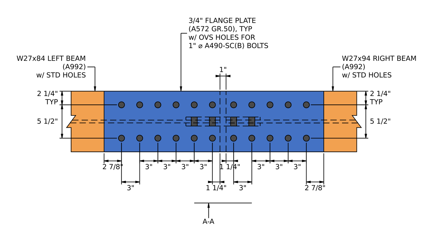
Plan of the flange splice. The 3/4 in flange plate has two bolt lines at a 5 1/2 in gage, six bolt columns on the W27x84 side and five on the W27x94 side, all at 3 in spacing. The beam ends are 1 in apart.
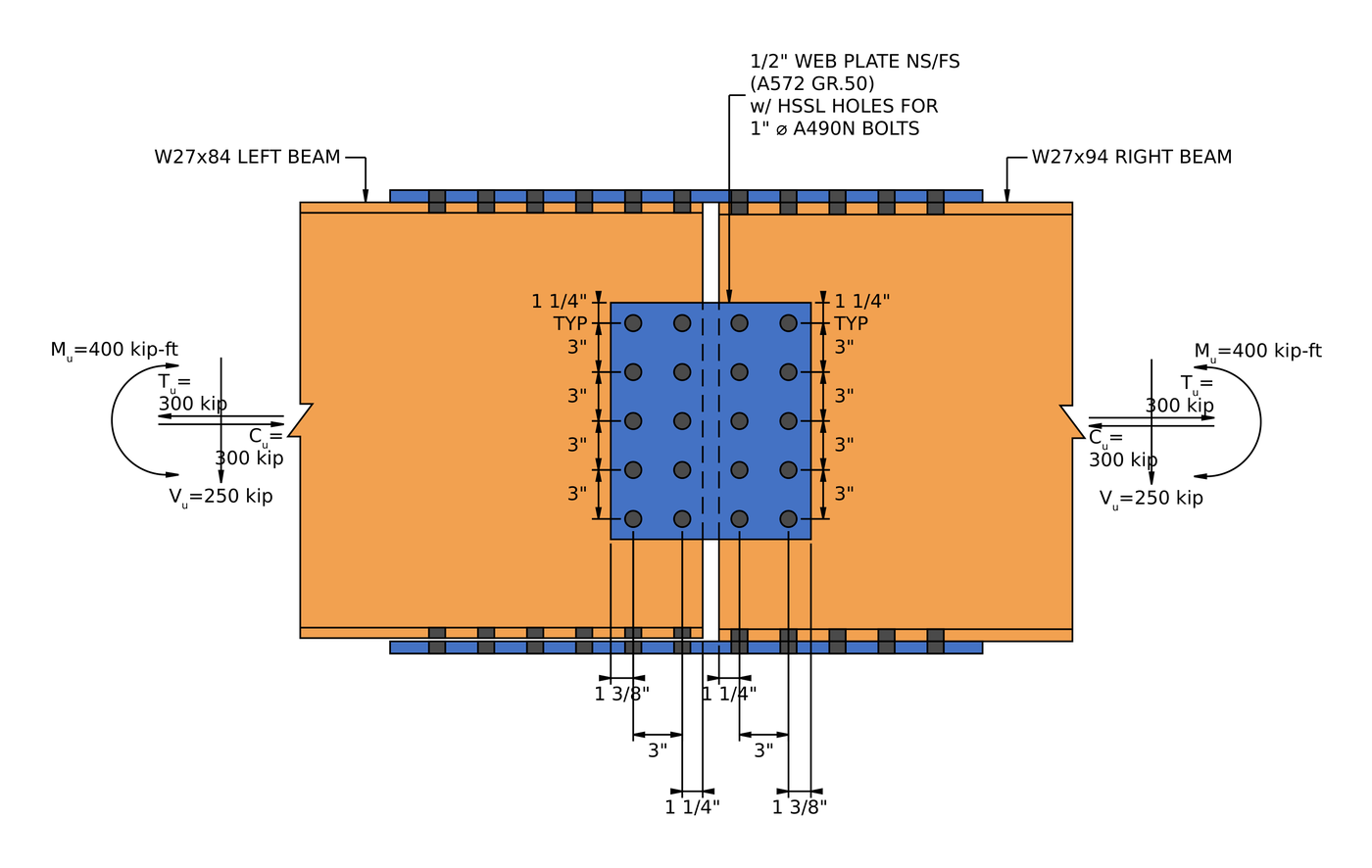
Section A-A. The web plates are 14 1/2 in deep, with five rows of two bolts on each side of the joint at 3 in spacing. The loads are shown at the splice.
Beam splice connection design: the steps at a glance
The loads are split between the flanges and the web first. Then the flange plate splice is checked on both sides of the joint, and then the web plate splice.
- Check the detailing limits for the flange plate bolts.
- Find the flange force and check slip of the slip-critical flange bolts.
- Check bolt bearing and tear-out on the flange plate.
- Check bolt bearing and tear-out on the beam flange.
- Check block shear of the flange plate for three tear-out patterns.
- Check block shear of the beam flange.
- Check tension yielding and rupture of the flange plate.
- Check tension rupture of the beam, with shear lag.
- Check flexural rupture of the beam at the flange bolt holes.
- Check the flange plate in compression.
- Repeat the flange checks for the second beam.
- Check the detailing limits for the web plate bolts.
- Check slip of the web bolt group under the resultant of shear and axial load.
- Check bolt bearing on the web plates for shear, axial load and their interaction.
- Check bolt bearing on the beam web for shear, axial load and their interaction.
- Check block shear of the web plates for shear, axial load and their interaction.
- Check block shear of the beam web for axial load.
- Check shear yielding and shear rupture of the web plates.
- Check tension yielding and rupture of the web plates.
- Check tension rupture of the beam web, with shear lag.
- Check the web plates in compression.
- Repeat the web checks for the second beam.
Design inputs for this example
The design code is AISC 360-16 LRFD. Section properties are from the AISC Manual. The left beam is the W27x84 and the right beam is the W27x94.
| Load | Symbol | Value |
|---|---|---|
| Factored vertical shear | [mathin] V_{u} [mathin] | 250 kip |
| Factored axial tension | [mathin] T_{u} [mathin] | 300 kip |
| Factored axial compression | [mathin] C_{u} [mathin] | 300 kip |
| Factored strong-axis moment | [mathin] M_{u} [mathin] | 400 kip-ft |
| Beam property | Symbol | Left beam | Right beam |
|---|---|---|---|
| Section | W27x84, A992 | W27x94, A992 | |
| Depth | [mathin] d [mathin] | 26.7 in | 26.9 in |
| Web thickness | [mathin] t_{w} [mathin] | 0.46 in | 0.49 in |
| Flange width | [mathin] b_{f} [mathin] | 10 in | 10 in |
| Flange thickness | [mathin] t_{f} [mathin] | 0.64 in | 0.745 in |
| Area | [mathin] A [mathin] | 24.7 in² | 27.6 in² |
| Elastic section modulus | [mathin] S_{x} [mathin] | 213.65 in³ | 242.89 in³ |
| Yield / tensile stress | [mathin] F_{y},\ F_{u} [mathin] | 50 ksi / 65 ksi | 50 ksi / 65 ksi |
| Clearance between beam ends | [mathin] c_{lr} [mathin] | 1 in |
| Flange plate splice | Symbol | Left side | Right side |
|---|---|---|---|
| Flange plate width / thickness | [mathin] b_{fp},\ t_{fp} [mathin] | 10 in / 0.75 in, A572 Gr. 50 | |
| Plate yield / tensile stress | [mathin] F_{yp},\ F_{up} [mathin] | 50 ksi / 65 ksi | |
| Bolts | 1 in A490-SC, Class B, one slip plane | ||
| Bolt nominal tensile / shear stress | [mathin] F_{nt},\ F_{nv} [mathin] | 113 ksi / 68 ksi | |
| Holes in plate / beam flange | Oversized (OVS) / standard (STD) | ||
| Bolt rows / gage | [mathin] n_{r},\ g_{a} [mathin] | 2 / 5.5 in | 2 / 5.5 in |
| Bolt columns / column spacing | [mathin] n_{c},\ s_{c} [mathin] | 6 / 3 in | 5 / 3 in |
| Vertical edge distance on plate / beam flange | [mathin] L_{ev,fp},\ L_{ev,c} [mathin] | 2.25 in / 2.25 in | 2.25 in / 2.25 in |
| Horizontal edge distance on plate / beam flange | [mathin] L_{eh,fp},\ L_{eh,c} [mathin] | 2.875 in / 1.25 in | 2.875 in / 1.25 in |
| Web plate splice (same on both sides) | Symbol | Value |
|---|---|---|
| Web plates | Two plates, one each face of the web, A572 Gr. 50 | |
| Plate depth / thickness of one plate | [mathin] d_{wp},\ t_{wp} [mathin] | 14.5 in / 0.5 in |
| Plate length from the beam end bolts to the splice side | [mathin] L_{wp} [mathin] | 5.625 in |
| Plate yield / tensile stress | [mathin] F_{yp},\ F_{up} [mathin] | 50 ksi / 65 ksi |
| Bolts | 1 in A490-SC, Class A, two slip planes | |
| Holes in plate / beam web | Short-slotted horizontal (HSSL) / standard (STD) | |
| Bolt rows / row spacing | [mathin] n_{r},\ s_{r} [mathin] | 5 / 3 in |
| Bolt columns / column spacing | [mathin] n_{c},\ s_{c} [mathin] | 2 / 3 in |
| Vertical edge distance on plate | [mathin] L_{ev,wp} [mathin] | 1.25 in |
| Horizontal edge distance on plate / beam web | [mathin] L_{eh,wp},\ L_{eh,c} [mathin] | 1.375 in / 1.25 in |
How the beam splice shares the load between flanges and web
Before any check, the splice has to decide which plates carry which load. The report proportions the axial load to the web by the web area over the total gross area of the beam, and gives the rest of the axial load and all of the moment to the flanges. The web also carries all of the shear.
The axial force on the web is:
[math] C_{web} = T_{web} = 135.34\,kip [math]
The flange force is half of the remaining axial load plus the moment divided by the distance between the flange centroids. [mathin] C_{bp} [mathin] is any compression carried by direct bearing between the beam ends. The beams are 1 in apart, so nothing bears and it is zero:
[math] C_{flange} = \frac{C_{u} – C_{bp} – C_{web}}{2} + \frac{M_{u}}{d_{c} – t_{fc}} [math]
[math] C_{flange} = \frac{(300\,kip) – (0\,kip) – (135.34\,kip)}{2} + \frac{(400\,kip\text{-}ft)}{(26.7\,in) – (0.64\,in)} = 266.52\,kip [math]
Tension and compression are both 300 kip, so [mathin] T_{flange} [mathin] is the same, and the design flange force is:
[math] P_{flange} = \max\left( C_{flange},\, T_{flange} \right) = 266.52\,kip [math]
The report uses the W27x84’s depth and flange thickness for the moment arm on both sides. It is the shallower of the two beams, so its lever arm is shorter and the flange force is larger, which is conservative for the W27x94 side.
The web bolts see the shear and the web axial load together. Their resultant is:
[math] R_{u} = \sqrt{V_{u}^{2} + P_{web}^{2}} = \sqrt{(250\,kip)^{2} + (135.34\,kip)^{2}} = 284.28\,kip [math]
Part 1: the flange plate splice
Steps 1 to 10 check the flange plate and the W27x84 flange on the left side for the 266.52 kip flange force. Step 11 repeats them for the W27x94 on the right.
Step 1: Detailing limits for the flange plate bolts (AISC 360-16 J3.3, J3.4, J3.5)
Before any strength check, the bolt layout has to be buildable and match the assumptions behind the strength equations. Bolts that are too close tear between the holes, and edges that are too close tear out.
The minimum bolt spacing is [mathin] 2\tfrac{2}{3} d_{b} [mathin] from J3.3, and the maximum here is 6 in. The minimum edge distance for a 1 in bolt is 1 1/4 in from Table J3.4, which is the limit on the beam flange, where the holes are standard. The flange plate has oversized holes, so Table J3.5 adds 1/8 in and its edge distance limits are 1.375 in. The gage has its own minimum, so that the two bolt lines fit across the flange with room to install the bolts.
| Detailing limit | Limit (in) | Actual (in) | DCR | Result |
|---|---|---|---|---|
| Minimum bolt gage | 4.875 | 5.500 | 0.886 | PASS |
| Minimum bolt column spacing | 2.667 | 3.000 | 0.889 | PASS |
| Maximum bolt column spacing | 6.000 | 3.000 | 0.500 | PASS |
| Plate minimum vertical edge distance | 1.375 | 2.250 | 0.611 | PASS |
| Plate minimum horizontal edge distance | 1.375 | 2.875 | 0.478 | PASS |
| Beam flange minimum vertical edge distance | 1.250 | 2.250 | 0.556 | PASS |
| Beam flange minimum horizontal edge distance | 1.250 | 1.250 | 1.000 | PASS |
For a minimum limit the ratio is limit over actual, and for a maximum it is actual over limit. The governing row is the horizontal edge distance on the beam flange, from the end of the beam to the first bolt column:
[math] DCR = \frac{1.25\,in}{1.25\,in} = 1 [math]
DCR = 1.000 ≤ 1.0, OK
A ratio of 1.0 means the edge distance is at the code minimum, which is common in detailing. A short beam end distance also keeps the unbraced length of the flange plate short in Step 10.
Step 2: Slip critical bolt strength at the flange (AISC 360-16 J3.8)
The flange plate bolts have to carry the flange force without slipping. These bolts are slip-critical because the flange plate has oversized holes, which AISC 360-16 J3.2 allows only in slip-critical connections.
Where [mathin] \phi = 0.85 [mathin] is the resistance factor for oversized holes, [mathin] \mu = 0.5 [mathin] is the mean slip coefficient for Class B faying surfaces, [mathin] D_{u} = 1.13 [mathin] relates the mean installed pretension to the specified minimum, [mathin] h_{f} = 0.85 [mathin] is the filler factor, [mathin] T_{b} = 64\,kip [mathin] is the minimum pretension of a 1 in A490 bolt from Table J3.1, and there is [mathin] N_{s} = 1 [mathin] slip plane:
[math] \phi R_{n} = \phi\, \mu\, D_{u}\, h_{f}\, T_{b}\, N_{s}\, n_{r}\, n_{c} [math]
[math] \phi R_{n} = (0.85) \times (0.5) \times (1.13) \times (0.85) \times (64\,kip) \times (1) \times (2) \times (6) [math]
[math] \phi R_{n} = 313.51\,kip [math]
DCR = 266.52 kip / 313.51 kip = 0.850 < 1.0, OK
J3.8 sets the filler factor at 1.0 when there is no filler or one filler between the plies, and 0.85 for two or more. The W27x84 is 0.2 in shallower than the W27x94, so its flanges sit inside the plane of the flange plates and need packing. The report designs that side for the 0.85 factor.
Step 3: Bolt bearing and tear-out on the flange plate (AISC 360-16 J3.10)
Slip-critical bolts must also work as bearing bolts, in case the joint does slip. Each bolt pushes on the edge of its hole in the plate. The plate either deforms at the hole (bolt bearing, capped at 2.4 d t Fu) or tears a strip out to the next hole or to the end of the plate (tear-out, 1.2 lc t Fu).
The clear distance for the end bolts, with [mathin] d_{h} = 1.25\,in [mathin] for the oversized holes, is:
[math] l_{c1} = L_{eh,fp} – \frac{d_{h}}{2} = (2.875\,in) – \frac{(1.25\,in)}{2} = 2.25\,in [math]
Between the other bolts:
[math] l_{c2} = s_{c} – d_{h} = (3\,in) – (1.25\,in) = 1.75\,in [math]
The end bolt in each of the two lines uses [mathin] l_{c1} [mathin], and the other five in each line use [mathin] l_{c2} [mathin]:
[math] \phi R_{n} = \phi \left[ \min\left(1.2\, l_{c1},\, 2.4\, d_{b}\right) t_{fp} F_{up}\, n_{r} + \min\left(1.2\, l_{c2},\, 2.4\, d_{b}\right) t_{fp} F_{up}\, n_{r} \left( n_{c} – 1 \right) \right] [math]
[math] \phi R_{n} = (0.75) \times \left[ \min\left(1.2 \times 2.25\,in,\, 2.4 \times 1\,in\right)(0.75\,in)(65\,ksi)(2) + \min\left(1.2 \times 1.75\,in,\, 2.4 \times 1\,in\right)(0.75\,in)(65\,ksi)(2)(6 – 1) \right] [math]
[math] \phi R_{n} = 943.31\,kip [math]
DCR = 266.52 kip / 943.31 kip = 0.283 < 1.0, OK
The end bolts are capped by bearing at 2.4 d, because their 2 7/8 in end distance is long. The inner bolts are limited by tear-out between the oversized holes.
Step 4: Bolt bearing and tear-out on the beam flange (AISC 360-16 J3.10)
The same check applies to the beam flange, which has standard holes ([mathin] d_{h} = 1.125\,in [mathin]) and is 0.64 in thick on the W27x84. Its end bolts are only 1 1/4 in from the end of the beam, so tear-out governs them.
[math] l_{c1} = L_{eh,c} – \frac{d_{h}}{2} = (1.25\,in) – \frac{(1.125\,in)}{2} = 0.6875\,in [math]
[math] l_{c2} = s_{c} – d_{h} = (3\,in) – (1.125\,in) = 1.875\,in [math]
[math] \phi R_{n} = \phi \left[ \min\left(1.2\, l_{c1},\, 2.4\, d_{b}\right) t_{f} F_{u}\, n_{r} + \min\left(1.2\, l_{c2},\, 2.4\, d_{b}\right) t_{f} F_{u}\, n_{r} \left( n_{c} – 1 \right) \right] [math]
[math] \phi R_{n} = (0.75) \times \left[ \min\left(1.2 \times 0.6875\,in,\, 2.4 \times 1\,in\right)(0.64\,in)(65\,ksi)(2) + \min\left(1.2 \times 1.875\,in,\, 2.4 \times 1\,in\right)(0.64\,in)(65\,ksi)(2)(6 – 1) \right] [math]
[math] \phi R_{n} = 753.48\,kip [math]
DCR = 266.52 kip / 753.48 kip = 0.354 < 1.0, OK
Step 5: Block shear of the flange plate (AISC 360-16 J4.3)
A block of the flange plate can tear out along the bolt lines: shear along a line of holes plus tension across the plate. With two bolt lines there are three ways for this to happen, and the weakest one governs. Each hole adds 1/16 in for damage during punching (B4.3), and [mathin] d_{h} = 1.25\,in [mathin] for the oversized holes.
L pattern: one shear plane, tension across the bolts to one edge
[math] A_{nt} = t_{fp} \left[ (n_{r} – 2)\, s_{r} + g_{a} + L_{ev,fp} – (n_{r} – 0.5)\left( d_{h} + 0.0625\,in \right) \right] [math]
[math] A_{nt} = (0.75\,in) \times \left[ (2 – 2)(3\,in) + 5.5\,in + 2.25\,in – (2 – 0.5)(1.25\,in + 0.0625\,in) \right] = 4.3359\,in^{2} [math]
[math] A_{gv} = t_{fp} \left[ L_{eh,fp} + (n_{c} – 1)\, s_{c} \right] = (0.75\,in) \times \left[ 2.875\,in + (6 – 1)(3\,in) \right] = 13.406\,in^{2} [math]
[math] A_{nv} = t_{fp} \left[ L_{eh,fp} + (n_{c} – 1)\, s_{c} – (n_{c} – 0.5)\left( d_{h} + 0.0625\,in \right) \right] = (0.75\,in) \times \left[ 2.875\,in + (5)(3\,in) – (5.5)(1.3125\,in) \right] = 7.9922\,in^{2} [math]
With [mathin] U_{bs} = 1 [mathin] for uniform tension:
[math] \phi R_{n} = \phi \left( 0.6\, F_{up} A_{nv} + U_{bs} F_{up} A_{nt} \right) \le \phi \left( 0.6\, F_{yp} A_{gv} + U_{bs} F_{up} A_{nt} \right) [math]
[math] \phi R_{n} = (0.75) \left( 0.6 \times 65 \times 7.9922 + 1 \times 65 \times 4.3359 \right) \le (0.75) \left( 0.6 \times 50 \times 13.406 + 1 \times 65 \times 4.3359 \right) [math]
[math] \phi R_{n} = 445.15\,kip [math]
U pattern: two shear planes, tension between the bolt lines
[math] A_{nt} = t_{fp} \left[ (n_{r} – 2)\, s_{r} + g_{a} – (n_{r} – 1)\left( d_{h} + 0.0625\,in \right) \right] = (0.75\,in) \times \left[ 0 + 5.5\,in – (1)(1.3125\,in) \right] = 3.1406\,in^{2} [math]
[math] A_{gv} = 2\, t_{fp} \left[ L_{eh,fp} + (n_{c} – 1)\, s_{c} \right] = 26.813\,in^{2} [math]
[math] A_{nv} = 2\, t_{fp} \left[ L_{eh,fp} + (n_{c} – 1)\, s_{c} – (n_{c} – 0.5)\left( d_{h} + 0.0625\,in \right) \right] = 15.984\,in^{2} [math]
[math] \phi R_{n} = (0.75) \left( 0.6 \times 65 \times 15.984 + 1 \times 65 \times 3.1406 \right) \le (0.75) \left( 0.6 \times 50 \times 26.813 + 1 \times 65 \times 3.1406 \right) = 620.65\,kip [math]
2L pattern: two shear planes, tension from each bolt line to its edge
[math] A_{nt} = 2\, t_{fp} \left[ L_{ev,fp} – 0.5\left( d_{h} + 0.0625\,in \right) \right] = 2 \times (0.75\,in) \times \left[ 2.25\,in – 0.5 \times (1.3125\,in) \right] = 2.3906\,in^{2} [math]
[math] \phi R_{n} = (0.75) \left( 0.6 \times 65 \times 15.984 + 1 \times 65 \times 2.3906 \right) \le (0.75) \left( 0.6 \times 50 \times 26.813 + 1 \times 65 \times 2.3906 \right) = 584.09\,kip [math]
Governing block shear
[math] \phi R_{n} = \min\left( 445.15\,kip,\, 620.65\,kip,\, 584.09\,kip \right) = 445.15\,kip [math]
DCR = 266.52 kip / 445.15 kip = 0.599 < 1.0, OK
The L pattern governs because it has only one shear plane.
Step 6: Block shear of the beam flange (AISC 360-16 J4.3)
The beam flange can tear out the same way. The critical block is the 2L pattern: the two outer strips of flange shear along the bolt lines from the beam end and pull away in tension. The beam flange has standard holes, [mathin] d_{h} = 1.125\,in [mathin].
[math] A_{nt} = t_{f} \left[ b_{f} – g_{a} – (n_{r} – 1)\left( d_{h} + 0.0625\,in \right) \right] = (0.64\,in) \times \left[ 10\,in – 5.5\,in – (1)(1.125\,in + 0.0625\,in) \right] = 2.12\,in^{2} [math]
[math] A_{gv} = 2\, t_{f} \left[ L_{eh,c} + (n_{c} – 1)\, s_{c} \right] = 2 \times (0.64\,in) \times \left[ 1.25\,in + (5)(3\,in) \right] = 20.8\,in^{2} [math]
[math] A_{nv} = 2\, t_{f} \left[ L_{eh,c} + (n_{c} – 1)\, s_{c} – (n_{c} – 0.5)\left( d_{h} + 0.0625\,in \right) \right] = 2 \times (0.64\,in) \times \left[ 16.25\,in – (5.5)(1.1875\,in) \right] = 12.44\,in^{2} [math]
[math] \phi R_{n} = (0.75) \left( 0.6 \times 65 \times 12.44 + 1 \times 65 \times 2.12 \right) \le (0.75) \left( 0.6 \times 50 \times 20.8 + 1 \times 65 \times 2.12 \right) [math]
[math] \phi R_{n} = 467.22\,kip [math]
DCR = 266.52 kip / 467.22 kip = 0.570 < 1.0, OK
Step 7: Tension yielding and rupture of the flange plate (AISC 360-16 J4.1)
On the tension flange, the flange plate is a short tension member. Its gross section must not yield, and its net section through the row of holes must not rupture.
Tension yielding (Eq. J4-1)
[math] \phi R_{n,ty} = \phi\, F_{yp}\, t_{fp}\, b_{fp} = (0.9) \times (50\,ksi) \times (0.75\,in) \times (10\,in) = 337.5\,kip [math]
Tension rupture (Eq. J4-2)
[math] \phi R_{n,tr} = \phi\, F_{up}\, t_{fp} \left[ b_{fp} – n_{r}\left( d_{h} + 0.0625\,in \right) \right] [math]
[math] \phi R_{n,tr} = (0.75) \times (65\,ksi) \times (0.75\,in) \times \left[ 10\,in – (2) \times (1.3125\,in) \right] = 269.65\,kip [math]
[math] \phi R_{n} = \min\left( 337.5\,kip,\, 269.65\,kip \right) = 269.65\,kip [math]
DCR = 266.52 kip / 269.65 kip = 0.988 < 1.0, OK
This is the governing check for the flange plates. The oversized holes take 2.625 in out of a 10 in plate, so net section rupture controls well below gross yielding. A wider plate is not an option here because the plate already matches the 10 in flange width, so the fix is a thicker plate.
Step 8: Tension rupture of the beam with shear lag (AISC 360-16 D3, J4.1)
The flange force has to get into the beam as well. Half the beam, a WT made of one flange and half the web, is treated as the tension member. The bolts connect only the flange, so the web lags behind in picking up stress, and the shear lag factor U reduces the effective net area.
From Table D3.1 case 2, where [mathin] \bar{y} = 3.5359\,in [mathin] is the distance from the flange to the centroid of the WT and l is the length of the connection, from the first bolt column to the last:
[math] U = 1 – \frac{\bar{y}}{l} = 0.76437 [math]
[math] \phi R_{n,tr} = \phi\, F_{u}\, U \left[ 0.5\, A – n_{r}\left( d_{h} + 0.0625\,in \right) t_{f} \right] [math]
[math] \phi R_{n,tr} = (0.75) \times (65\,ksi) \times (0.76437) \times \left[ 0.5 \times (24.7\,in^{2}) – (2) \times (1.125\,in + 0.0625\,in) \times (0.64\,in) \right] [math]
[math] \phi R_{n,tr} = 403.56\,kip [math]
DCR = 266.52 kip / 403.56 kip = 0.660 < 1.0, OK
Step 9: Flexural rupture of the beam at the flange bolt holes (AISC 360-16 F13.1)
The bolt holes take material out of the beam’s tension flange at the splice. F13.1 checks whether those holes reduce the beam’s flexural strength, and if they do, by how much.
Gross and net area of the tension flange
[math] A_{fg} = b_{f}\, t_{f} = (10\,in) \times (0.64\,in) = 6.4\,in^{2} [math]
[math] A_{fn} = A_{fg} – n_{r}\left( d_{h} + 0.0625\,in \right) t_{f} = (6.4\,in^{2}) – (2) \times (1.1875\,in) \times (0.64\,in) = 4.88\,in^{2} [math]
Does tensile rupture apply?
[math] \frac{F_{y}}{F_{u}} = \frac{50\,ksi}{65\,ksi} = 0.76923 \le 0.8 \;\Rightarrow\; Y_{t} = 1 [math]
[math] F_{u} A_{fn} = (65\,ksi) \times (4.88\,in^{2}) = 317.2\,kip [math]
[math] Y_{t} F_{y} A_{fg} = (1) \times (50\,ksi) \times (6.4\,in^{2}) = 320\,kip [math]
Because [mathin] F_{u} A_{fn} \lt Y_{t} F_{y} A_{fg} [mathin] by a small margin, the net flange ruptures before the gross flange yields and the limit state of tensile rupture applies.
Flexural strength at the holes (Eq. F13-1)
[math] M_{n} = \frac{F_{u} A_{fn}}{A_{fg}}\, S_{x} = \frac{(65\,ksi) \times (4.88\,in^{2})}{(6.4\,in^{2})} \times (213.65\,in^{3}) = 882.4\,kip\text{-}ft [math]
As a flange force, to compare with [mathin] P_{flange} [mathin]:
[math] \phi R_{n} = \frac{\phi\, M_{n}}{d – t_{f}} = \frac{(0.9) \times (882.4\,kip\text{-}ft)}{(26.7\,in) – (0.64\,in)} = 365.69\,kip [math]
DCR = 266.52 kip / 365.69 kip = 0.729 < 1.0, OK
Step 10: Compression strength of the flange plate (AISC 360-16 J4.4)
On the compression flange the flange plate is a short column across the gap between the beam ends. If it is stocky enough, it reaches its yield load without buckling, and AISC 360-16 J4.4 lets you skip the full Chapter E column check.
The unbraced length is [mathin] L_{b} = 3.5\,in [mathin], the distance between the first bolt columns on either side of the joint: 1.25 in edge distance, the 1 in gap, and 1.25 in again. With [mathin] K = 1.2 [mathin] (Commentary Table C-A-7.1, rotation fixed at both ends, translation free at one) and [mathin] r = t_{fp} / \sqrt{12} [mathin] for a rectangular plate:
[math] \frac{K L}{r} = \frac{(1.2) \times (3.5\,in)}{(0.75\,in) / \sqrt{12}} = 19.4 \le 25 [math]
Since KL/r is no more than 25, Eq. J4-6 applies:
[math] \phi R_{n} = \phi\, F_{yp}\, t_{fp}\, b_{fp} = (0.9) \times (50\,ksi) \times (0.75\,in) \times (10\,in) = 337.5\,kip [math]
DCR = 266.52 kip / 337.5 kip = 0.790 < 1.0, OK
Step 11: Flange plate splice on the W27x94 side
The right side of the splice carries the same 266.52 kip flange force through the same plate, but into a W27x94 with a thicker flange (0.745 in) and one fewer bolt column (five). Every check in Steps 1 to 10 is repeated with those values, and the detailing table is identical.
The slip check is the one that changes most. The report uses [mathin] h_{f} = 1 [mathin] on this side, the J3.8 value for no filler or one filler, and five bolt columns:
[math] \phi R_{n} = (0.85) \times (0.5) \times (1.13) \times (1) \times (64\,kip) \times (1) \times (2) \times (5) = 307.36\,kip [math]
DCR = 266.52 kip / 307.36 kip = 0.867 < 1.0, OK
Flexural rupture uses the W27x94 flange and section modulus:
[math] A_{fg} = (10\,in)(0.745\,in) = 7.45\,in^{2}, \quad A_{fn} = 5.6806\,in^{2} [math]
[math] F_{u} A_{fn} = 369.24\,kip \lt Y_{t} F_{y} A_{fg} = 372.5\,kip [math]
[math] M_{n} = \frac{(65\,ksi) \times (5.6806\,in^{2})}{(7.45\,in^{2})} \times (242.89\,in^{3}) = 1003.2\,kip\text{-}ft [math]
[math] \phi R_{n} = \frac{(0.9) \times (1003.2\,kip\text{-}ft)}{(26.9\,in) – (0.745\,in)} = 414.24\,kip [math]
The other right side results:
| Check | Key values | Capacity | DCR |
|---|---|---|---|
| Bearing on flange plate | [mathin] n_{c} = 5 [mathin] | 789.75 kip | 0.337 |
| Bearing on beam flange | [mathin] t_{f} = 0.745\,in [mathin] | 713.66 kip | 0.373 |
| Block shear of flange plate, L | [mathin] A_{nt} = 4.3359,\ A_{gv} = 11.156,\ A_{nv} = 6.7266\,in^{2} [mathin] | 408.13 kip | 0.653 |
| Block shear of flange plate, U | [mathin] A_{nt} = 3.1406,\ A_{gv} = 22.313,\ A_{nv} = 13.453\,in^{2} [mathin] | 546.61 kip | |
| Block shear of flange plate, 2L | [mathin] A_{nt} = 2.3906\,in^{2} [mathin] | 510.05 kip | |
| Block shear of beam flange, 2L | [mathin] A_{nt} = 2.4678,\ A_{gv} = 19.742,\ A_{nv} = 11.78\,in^{2} [mathin] | 464.88 kip | 0.573 |
| Flange plate tension | Same plate as left | 269.65 kip | 0.988 |
| Beam tension rupture | [mathin] \bar{y} = 3.467\,in,\ U = 0.7112 [mathin] | 417.11 kip | 0.639 |
| Flexural rupture (F13.1) | [mathin] S_{x} = 242.89\,in^{3} [mathin] | 414.24 kip | 0.643 |
| Flange plate compression | [mathin] KL/r = 19.4 [mathin] | 337.5 kip | 0.790 |
The right side has five bolt columns against six on the left, so its slip and block shear ratios are higher. The beam checks are lower because the W27x94 flange is thicker. Flange plate tension is the same 0.988 on both sides, since it depends only on the plate.
Part 2: the web plate splice
Steps 12 to 21 check the two web plates and the W27x84 web on the left side, for the 250 kip shear and the 135.34 kip web axial force. Step 22 covers the W27x94 side. Because the web carries axial load as well as shear, the bearing and block shear checks are done in each direction and then combined.
Step 12: Detailing limits for the web plate bolts (AISC 360-16 J3.3, J3.4, J3.5)
The web bolt layout has to meet the same spacing and edge distance rules as the flange, and the web plates have to be deep enough to stabilise the beam web but fit between the flanges.
The horizontal short slots in the plate run perpendicular to the plate’s vertical end edge, so Table J3.5 adds 1/8 in to the horizontal edge distance, giving 1.375 in. The vertical edge distance stays at the Table J3.4 value of 1.25 in.
| Detailing limit | Limit (in) | Actual (in) | DCR | Result |
|---|---|---|---|---|
| Minimum bolt row spacing | 2.667 | 3.000 | 0.889 | PASS |
| Maximum bolt row spacing | 6.000 | 3.000 | 0.500 | PASS |
| Minimum bolt column spacing | 2.667 | 3.000 | 0.889 | PASS |
| Maximum bolt column spacing | 6.000 | 3.000 | 0.500 | PASS |
| Plate minimum vertical edge distance | 1.250 | 1.250 | 1.000 | PASS |
| Plate minimum horizontal edge distance | 1.375 | 1.375 | 1.000 | PASS |
| Minimum connection depth | 11.500 | 14.500 | 0.793 | PASS |
| Maximum connection depth | 23.000 | 14.500 | 0.630 | PASS |
DCR = 1.000 ≤ 1.0, OK
Both plate edge distances sit at the code minimum. That keeps the web plates compact, which matters for the compression check in Step 21.
Step 13: Slip critical bolt strength at the web (AISC 360-16 J3.8)
The web bolts carry the shear and the web axial force together, so the slip check uses their resultant, 284.28 kip. The bolts are slip-critical because the plates have short slots that run parallel to the axial load.
Where [mathin] \phi = 0.85 [mathin] for short slots parallel to the load, [mathin] \mu = 0.3 [mathin] for Class A faying surfaces, [mathin] D_{u} = 1.13 [mathin], [mathin] h_{f} = 1 [mathin], [mathin] T_{b} = 64\,kip [mathin], and [mathin] N_{s} = 2 [mathin] slip planes because there is a web plate on each face of the web:
[math] \phi R_{n} = \phi\, \mu\, D_{u}\, h_{f}\, T_{b}\, N_{s}\, n_{r}\, n_{c} [math]
[math] \phi R_{n} = (0.85) \times (0.3) \times (1.13) \times (1) \times (64\,kip) \times (2) \times (5) \times (2) [math]
[math] \phi R_{n} = 368.83\,kip [math]
DCR = 284.28 kip / 368.83 kip = 0.771 < 1.0, OK
Two slip planes double the slip resistance of each bolt, so ten bolts are enough even with the lower Class A slip coefficient.
Step 14: Bolt bearing on the web plates (AISC 360-16 J3.10)
The web plate holes are loaded in two directions at once: down by the shear and along the beam by the axial force. Bolt bearing and tear-out are checked separately in each direction, using the clear distances that apply in that direction, and then combined. Both plates work together, so the thickness is [mathin] 2t_{wp} = 1\,in [mathin].
Shear direction
Across the slot, the hole dimension is [mathin] d_{h} = 1.125\,in [mathin]. The bottom bolt in each column tears toward the bottom edge of the plate, and the others toward the hole below:
[math] l_{c1} = L_{ev,wp} – \frac{d_{h}}{2} = (1.25\,in) – \frac{(1.125\,in)}{2} = 0.6875\,in, \quad l_{c2} = s_{r} – d_{h} = (3\,in) – (1.125\,in) = 1.875\,in [math]
The bracket sums one column of bolts, and [mathin] C / n_{r} [mathin] scales it to the whole group. The load is concentric, so the bolt group coefficient C is the number of bolts, 10:
[math] \phi R_{n} = \phi \left[ \min\left(1.2\, l_{c1},\, 2.4\, d_{b}\right) 2t_{wp} F_{up} + \min\left(1.2\, l_{c2},\, 2.4\, d_{b}\right) 2t_{wp} F_{up} \left( n_{r} – 1 \right) \right] \frac{C}{n_{r}} [math]
[math] \phi R_{n} = (0.75) \times \left[ \min\left(1.2 \times 0.6875\,in,\, 2.4\,in\right)(1\,in)(65\,ksi) + \min\left(1.2 \times 1.875\,in,\, 2.4\,in\right)(1\,in)(65\,ksi)(5 – 1) \right] \times \frac{10}{5} = 957.94\,kip [math]
DCR = 250 kip / 957.94 kip = 0.261 < 1.0, OK
Axial direction
Along the slot, the hole dimension is [mathin] d_{h} = 1.3125\,in [mathin]. The outer bolt in each row tears toward the plate’s end edge:
[math] l_{c1} = L_{eh,wp} – \frac{d_{h}}{2} = (1.375\,in) – \frac{(1.3125\,in)}{2} = 0.71875\,in, \quad l_{c2} = s_{c} – d_{h} = (3\,in) – (1.3125\,in) = 1.6875\,in [math]
[math] \phi R_{n} = \phi \left[ \min\left(1.2\, l_{c1},\, 2.4\, d_{b}\right) 2t_{wp} F_{up} + \min\left(1.2\, l_{c2},\, 2.4\, d_{b}\right) 2t_{wp} F_{up} \left( n_{c} – 1 \right) \right] \frac{C}{n_{c}} [math]
[math] \phi R_{n} = (0.75) \times \left[ \min\left(1.2 \times 0.71875\,in,\, 2.4\,in\right)(1\,in)(65\,ksi) + \min\left(1.2 \times 1.6875\,in,\, 2.4\,in\right)(1\,in)(65\,ksi)(2 – 1) \right] \times \frac{10}{2} = 703.83\,kip [math]
DCR = 135.34 kip / 703.83 kip = 0.192 < 1.0, OK
Interaction
The two directions are combined as a sum of squares, which treats the bearing strength as a circular interaction for a bolt loaded at an angle:
[math] \left( \frac{V_{u}}{\phi R_{n,v}} \right)^{2} + \left( \frac{P_{web}}{\phi R_{n,a}} \right)^{2} = \left( \frac{250}{957.94} \right)^{2} + \left( \frac{135.34}{703.83} \right)^{2} = 0.10508 [math]
DCR = 0.105 < 1.0, OK
Step 15: Bolt bearing on the beam web (AISC 360-16 J3.10)
The beam web has standard holes, [mathin] d_{h} = 1.125\,in [mathin], and is only 0.46 in thick on the W27x84, so it is weaker in bearing than the pair of plates.
Shear direction
Below each web bolt there is either another hole or a long stretch of web down to the bottom flange, so every bolt uses the clear distance between holes, [mathin] l_{c2} = 1.875\,in [mathin]:
[math] \phi R_{n} = \phi \min\left(1.2\, l_{c2},\, 2.4\, d_{b}\right) t_{w} F_{u}\, C = (0.75) \times \min\left(2.25\,in,\, 2.4\,in\right) \times (0.46\,in) \times (65\,ksi) \times (10) = 504.56\,kip [math]
DCR = 250 kip / 504.56 kip = 0.495 < 1.0, OK
Axial direction
Along the beam, the bolt column nearest the beam end tears out toward it, with [mathin] l_{c1} = L_{eh,c} – d_{h}/2 = 0.6875\,in [mathin]:
[math] \phi R_{n} = \phi \left[ \min\left(1.2\, l_{c1},\, 2.4\, d_{b}\right) t_{w} F_{u} + \min\left(1.2\, l_{c2},\, 2.4\, d_{b}\right) t_{w} F_{u} \left( n_{c} – 1 \right) \right] \frac{C}{n_{c}} = 344.78\,kip [math]
DCR = 135.34 kip / 344.78 kip = 0.393 < 1.0, OK
Interaction
[math] \left( \frac{250}{504.56} \right)^{2} + \left( \frac{135.34}{344.78} \right)^{2} = 0.39957 [math]
DCR = 0.400 < 1.0, OK
Step 16: Block shear of the web plates (AISC 360-16 J4.3)
A block of the web plates can tear out under the shear, under the axial force, or under both. Each direction is checked with its own tear-out pattern, and the two ratios are combined the same way as for bearing.
Shear load
The block shears along the inner bolt column to the bottom of the plates and tears in tension across the bottom row to the plate end. The tension area uses the slot length, [mathin] d_{h} = 1.3125\,in [mathin], and the shear area uses the slot width, 1.125 in:
[math] A_{nt} = 2t_{wp} \left[ (n_{c} – 1)\, s_{c} + L_{eh,wp} – (n_{c} – 0.5)\left( d_{h} + 0.0625\,in \right) \right] = (1\,in) \times \left[ (1)(3\,in) + 1.375\,in – 1.5(1.375\,in) \right] = 2.3125\,in^{2} [math]
[math] A_{gv} = 2t_{wp} \left[ L_{ev,wp} + (n_{r} – 1)\, s_{r} \right] = 13.25\,in^{2} [math]
[math] A_{nv} = 2t_{wp} \left[ d_{wp} – L_{ev,wp} – (n_{r} – 0.5)\left( d_{h} + 0.0625\,in \right) \right] = 7.9062\,in^{2} [math]
With two bolt columns the tension stress across the block is not uniform, so [mathin] U_{bs} = 0.5 [mathin], as the AISC Manual uses for multi-column bolt groups:
[math] \phi R_{n} = (0.75) \left( 0.6 \times 65 \times 7.9062 + 0.5 \times 65 \times 2.3125 \right) \le (0.75) \left( 0.6 \times 50 \times 13.25 + 0.5 \times 65 \times 2.3125 \right) = 287.62\,kip [math]
DCR = 250 kip / 287.62 kip = 0.869 < 1.0, OK
Axial load
Under axial load, the report checks two patterns. In the L pattern, the block tears in tension down the bolt rows and out the bottom edge, and shears along the top bolt row to the plate end:
[math] A_{nt} = 2t_{wp} \left[ (n_{r} – 1)\, s_{r} + L_{ev,wp} – (n_{r} – 0.5)\left( d_{h} + 0.0625\,in \right) \right] = 7.9063\,in^{2} [math]
[math] A_{gv} = 2t_{wp} \left[ L_{eh,wp} + (n_{c} – 1)\, s_{c} \right] = 4.375\,in^{2} [math]
[math] A_{nv} = 2t_{wp} \left[ L_{wp} – L_{eh,c} – (n_{c} – 0.5)\left( d_{h} + 0.0625\,in \right) \right] = (1\,in) \times \left[ 5.625\,in – 1.25\,in – 1.5(1.375\,in) \right] = 2.3125\,in^{2} [math]
[math] \phi R_{n,L} = (0.75) \left( 0.6 \times 65 \times 2.3125 + 1 \times 65 \times 7.9063 \right) \le (0.75) \left( 0.6 \times 50 \times 4.375 + 1 \times 65 \times 7.9063 \right) = 453.07\,kip [math]
In the U (or C) pattern, the block between the top and bottom bolt rows pulls out, shearing along both outer rows:
[math] A_{nt} = 2t_{wp} \left[ (n_{r} – 1)\, s_{r} – (n_{r} – 1)\left( d_{h} + 0.0625\,in \right) \right] = 7.25\,in^{2} [math]
[math] A_{gv} = 2 \cdot 2t_{wp} \left[ L_{eh,wp} + (n_{c} – 1)\, s_{c} \right] = 8.75\,in^{2}, \quad A_{nv} = 2 \cdot 2t_{wp} \left[ (n_{c} – 1)\, s_{c} + L_{eh,wp} – (n_{c} – 0.5)\left( d_{h} + 0.0625\,in \right) \right] = 4.625\,in^{2} [math]
[math] \phi R_{n,U} = 488.72\,kip [math]
[math] \phi R_{n} = \min\left( 453.07\,kip,\, 488.72\,kip \right) = 453.07\,kip [math]
DCR = 135.34 kip / 453.07 kip = 0.299 < 1.0, OK
Interaction
[math] \left( \frac{250}{287.62} \right)^{2} + \left( \frac{135.34}{453.07} \right)^{2} = 0.84471 [math]
DCR = 0.845 < 1.0, OK
The shear term alone contributes 0.755 of the 0.845.
Step 17: Block shear of the beam web (AISC 360-16 J4.3)
Under axial load, a block of the beam web around the bolts can pull out of the beam end: tension between the top and bottom bolt rows, and shear along both rows to the end of the beam. This is the C pattern.
[math] A_{nt} = t_{w} \left[ (n_{r} – 1)\, s_{r} – (n_{r} – 1)\left( d_{h} + 0.0625\,in \right) \right] = 3.335\,in^{2} [math]
[math] A_{gv} = 2t_{w} \left[ L_{eh,c} + (n_{c} – 1)\, s_{c} \right] = 3.91\,in^{2} [math]
[math] A_{nv} = 2t_{w} \left[ (n_{c} – 1)\, s_{c} + L_{eh,c} – (n_{c} – 0.5)\left( d_{h} + 0.0625\,in \right) \right] = 2.2713\,in^{2} [math]
[math] \phi R_{n} = (0.75) \left( 0.6 \times 65 \times 2.2713 + 1 \times 65 \times 3.335 \right) \le (0.75) \left( 0.6 \times 50 \times 3.91 + 1 \times 65 \times 3.335 \right) = 229.02\,kip [math]
DCR = 135.34 kip / 229.02 kip = 0.591 < 1.0, OK
Step 18: Shear yielding and shear rupture of the web plates (AISC 360-16 J4.2)
The two web plates carry the full 250 kip shear across the splice. Their gross section must not yield in shear, and their net section through the bolt holes must not rupture.
Shear yielding (Eq. J4-3)
[math] A_{gv} = d_{wp} \times 2t_{wp} = (14.5\,in) \times (1\,in) = 14.5\,in^{2} [math]
[math] \phi R_{n,sy} = \phi\, 0.6\, F_{yp}\, A_{gv} = (1) \times 0.6 \times (50\,ksi) \times (14.5\,in^{2}) = 435\,kip [math]
Shear rupture (Eq. J4-4)
[math] A_{nv} = 2t_{wp} \left[ d_{wp} – n_{r}\left( d_{h} + 0.0625\,in \right) \right] = (1\,in) \times \left[ 14.5\,in – 5 \times (1.1875\,in) \right] = 8.5625\,in^{2} [math]
[math] \phi R_{n,sr} = \phi\, 0.6\, F_{up}\, A_{nv} = (0.75) \times 0.6 \times (65\,ksi) \times (8.5625\,in^{2}) = 250.45\,kip [math]
[math] \phi R_{n} = \min\left( 435\,kip,\, 250.45\,kip \right) = 250.45\,kip [math]
DCR = 250 kip / 250.45 kip = 0.998 < 1.0, OK
This is the governing check of the whole beam splice. Five holes remove 41% of the plate depth, so shear rupture of the net section is far below shear yielding. Another bolt row or a deeper plate would add net area directly.
Step 19: Tension yielding and rupture of the web plates (AISC 360-16 J4.1)
Under axial tension, the web plates carry the 135.34 kip web force across the joint as a tension member.
[math] \phi R_{n,ty} = \phi\, F_{yp}\, 2t_{wp}\, d_{wp} = (0.9) \times (50\,ksi) \times (1\,in) \times (14.5\,in) = 652.5\,kip [math]
[math] \phi R_{n,tr} = \phi\, F_{up}\, 2t_{wp} \left[ d_{wp} – n_{r}\left( d_{h} + 0.0625\,in \right) \right] = (0.75) \times (65\,ksi) \times (1\,in) \times \left[ 14.5\,in – 5 \times (1.1875\,in) \right] = 417.42\,kip [math]
DCR = 135.34 kip / 417.42 kip = 0.324 < 1.0, OK
Step 20: Tension rupture of the beam web with shear lag (AISC 360-16 D3, J4.1)
The web axial force also has to get into the beam. Here the bolts connect only the web, so the flanges lag behind in picking up stress. The whole wide flange section is the tension member, and the shear lag factor uses [mathin] \bar{x} = 1.3614\,in [mathin], the distance from the web to the centroid of half the section, over the 3 in connection length:
[math] U = 1 – \frac{\bar{x}}{l} = 0.54639 [math]
[math] \phi R_{n} = \phi\, F_{u}\, U \left[ A – n_{r}\left( d_{h} + 0.0625\,in \right) t_{w} \right] = (0.75) \times (65\,ksi) \times (0.54639) \times \left[ 24.7\,in^{2} – 5 \times (1.1875\,in) \times (0.46\,in) \right] = 585.17\,kip [math]
DCR = 135.34 kip / 585.17 kip = 0.231 < 1.0, OK
Step 21: Compression strength of the web plates (AISC 360-16 J4.4, E3)
Under axial compression the web plates span the gap between the beam ends as short columns. Each plate can buckle on its own, so the radius of gyration is that of one 1/2 in plate, while the area is that of both plates.
With [mathin] K = 1.2 [mathin] and [mathin] L_{b} = 3.5\,in [mathin], the same unbraced length as the flange plates:
[math] \frac{K L}{r} = \frac{(1.2) \times (3.5\,in)}{(0.5\,in) / \sqrt{12}} = 29.098 \gt 25 [math]
KL/r is above 25, so J4.4 sends the plates to Chapter E. The slenderness is below [mathin] 4.71\sqrt{E/F_{y}} = 113.43 [mathin], so Eq. E3-2 applies:
[math] F_{e} = \frac{\pi^{2} E}{\left( KL/r \right)^{2}} = \frac{\pi^{2} \times (29000\,ksi)}{(29.098)^{2}} = 338.03\,ksi [math]
[math] F_{cr} = 0.658^{F_{y}/F_{e}} F_{y} = 0.658^{(50/338.03)} \times (50\,ksi) = 46.998\,ksi [math]
[math] \phi R_{n} = \phi\, F_{cr}\, 2t_{wp}\, d_{wp} = (0.9) \times (46.998\,ksi) \times (1\,in) \times (14.5\,in) = 613.33\,kip [math]
DCR = 135.34 kip / 613.33 kip = 0.221 < 1.0, OK
The 1/2 in web plates are thinner than the 3/4 in flange plates, so they cross the KL/r = 25 limit over the same 3.5 in length. Buckling only takes about 6% off the yield strength at this slenderness.
Step 22: Web plate splice on the W27x94 side
The web plates and bolt layout are the same on the right, so the plate checks (bearing on the plates, block shear of the plates, shear, tension and compression) give the same results as on the left. The beam web checks change because the W27x94 web is 0.49 in thick, and the slip check uses [mathin] h_{f} = 0.85 [mathin] on this side:
[math] \phi R_{n} = (0.85) \times (0.3) \times (1.13) \times (0.85) \times (64\,kip) \times (2) \times (5) \times (2) = 313.51\,kip [math]
DCR = 284.28 kip / 313.51 kip = 0.907 < 1.0, OK
| Check | Key values | Capacity | DCR |
|---|---|---|---|
| Bearing on beam web, shear | [mathin] t_{w} = 0.49\,in [mathin] | 537.47 kip | 0.465 |
| Bearing on beam web, axial | [mathin] t_{w} = 0.49\,in [mathin] | 367.27 kip | 0.368 |
| Bearing on beam web, interaction | 0.352 | ||
| Block shear of beam web | [mathin] A_{nt} = 3.5525,\ A_{gv} = 4.165,\ A_{nv} = 2.4194\,in^{2} [mathin] | 243.95 kip | 0.555 |
| Beam web tension rupture | [mathin] \bar{x} = 1.4177\,in,\ U = 0.52762,\ A = 27.6\,in^{2} [mathin] | 635.08 kip | 0.213 |
Summary of design checks
Flange plate splice
| Design check | Demand | Left capacity | Left DCR | Right capacity | Right DCR | Result |
|---|---|---|---|---|---|---|
| Detailing limits | 1.25 in | 1.25 in | 1.000 | 1.25 in | 1.000 | PASS |
| Slip of flange bolts | 266.522 kip | 313.507 kip | 0.850 | 307.360 kip | 0.867 | PASS |
| Bearing on flange plate | 266.522 kip | 943.312 kip | 0.283 | 789.750 kip | 0.337 | PASS |
| Bearing on beam flange | 266.522 kip | 753.480 kip | 0.354 | 713.663 kip | 0.373 | PASS |
| Block shear of flange plate | 266.522 kip | 445.148 kip | 0.599 | 408.129 kip | 0.653 | PASS |
| Block shear of beam flange | 266.522 kip | 467.220 kip | 0.570 | 464.880 kip | 0.573 | PASS |
| Flange plate tension | 266.522 kip | 269.648 kip | 0.988 | 269.648 kip | 0.988 | PASS |
| Beam tension rupture | 266.522 kip | 403.558 kip | 0.660 | 417.114 kip | 0.639 | PASS |
| Flexural rupture at holes | 266.522 kip | 365.691 kip | 0.729 | 414.238 kip | 0.643 | PASS |
| Flange plate compression | 266.522 kip | 337.500 kip | 0.790 | 337.500 kip | 0.790 | PASS |
Web plate splice
| Design check | Demand | Left capacity | Left DCR | Right capacity | Right DCR | Result |
|---|---|---|---|---|---|---|
| Detailing limits | 1.25 in | 1.25 in | 1.000 | 1.25 in | 1.000 | PASS |
| Slip of web bolt group | 284.281 kip | 368.832 kip | 0.771 | 313.507 kip | 0.907 | PASS |
| Bearing on web plates, shear | 250 kip | 957.938 kip | 0.261 | 957.938 kip | 0.261 | PASS |
| Bearing on web plates, axial | 135.336 kip | 703.828 kip | 0.192 | 703.828 kip | 0.192 | PASS |
| Bearing on web plates, interaction | 0.105 | 0.105 | PASS | |||
| Bearing on beam web, shear | 250 kip | 504.563 kip | 0.495 | 537.469 kip | 0.465 | PASS |
| Bearing on beam web, axial | 135.336 kip | 344.784 kip | 0.393 | 367.270 kip | 0.368 | PASS |
| Bearing on beam web, interaction | 0.400 | 0.352 | PASS | |||
| Block shear of web plates, shear | 250 kip | 287.625 kip | 0.869 | 287.625 kip | 0.869 | PASS |
| Block shear of web plates, axial | 135.336 kip | 453.070 kip | 0.299 | 453.070 kip | 0.299 | PASS |
| Block shear of web plates, interaction | 0.845 | 0.845 | PASS | |||
| Block shear of beam web | 135.336 kip | 229.015 kip | 0.591 | 243.951 kip | 0.555 | PASS |
| Web plate shear | 250 kip | 250.453 kip | 0.998 | 250.453 kip | 0.998 | PASS |
| Web plate tension | 135.336 kip | 417.422 kip | 0.324 | 417.422 kip | 0.324 | PASS |
| Beam web tension rupture | 135.336 kip | 585.166 kip | 0.231 | 635.084 kip | 0.213 | PASS |
| Web plate compression | 135.336 kip | 613.329 kip | 0.221 | 613.329 kip | 0.221 | PASS |
The beam splice passes every check. Shear rupture of the web plates governs at 0.998 on both sides, and tension rupture of the flange plates is next at 0.988. Both are net section checks through the bolt holes, so the plates, not the bolts or the beams, are what limit this splice. The detailing ratios of 1.000 mean the edge distances are at the code minimum, not that the connection is overstressed.
What to change if a check fails
- Web plate shear rupture or block shear: add a bolt row and make the web plates deeper, or use thicker plates.
- Flange plate tension rupture: use a thicker flange plate. The plate is already as wide as the beam flange, so width is not available.
- Slip of the flange or web bolts: add a bolt column, change to a Class B faying surface on the web, or reduce the number of fillers so the filler factor goes up to 1.0.
- Block shear or bearing on the beam flange or web: increase the edge distance at the beam end, or add bolt columns to lengthen the shear planes.
- Beam tension or flexural rupture at the holes: these depend on the beam and the hole layout, so use fewer holes across the flange, or move the splice to a point of lower moment.
- Plate compression: shorten the unbraced length by tightening the gap or the beam edge distance, or use thicker plates to bring KL/r down.
Frequently asked questions
How is the load shared between the flange plates and the web plates in a beam splice?
The web plates carry all of the shear. The axial load is split by area: the web takes its share of the gross area, here 135.34 kip of the 300 kip, and the flanges take the rest, half each. The moment goes entirely to the flanges as a tension and compression couple. In this example each flange plate carries 266.52 kip.
Why are the splice bolts slip-critical?
The flange plates have oversized holes and the web plates have short slots parallel to the axial load. Both give the erector room to fit the beams together, and AISC 360-16 J3.2 allows those holes only in slip-critical connections. Slip-critical bolts also keep the splice from moving when the moment or axial force reverses, so the beam behaves as continuous.
Why does the web plate check combine shear and axial results?
The web bolts are loaded diagonally, by the vertical shear and the horizontal axial force at the same time. The report checks bearing and block shear in each direction on its own, then adds the squares of the two ratios. A result below 1.0 means the combined load is inside the circular interaction curve. The slip check uses the resultant force directly.
Why is there a gap between the beam ends?
The 1 in gap gives erection tolerance, so the beams do not have to be cut to an exact length. Because the ends do not touch, no compression passes by direct bearing and all of it goes through the splice plates. The gap also sets the unbraced length of the plates for the compression check.
What happens when the two beams have different depths?
The flanges of the shallower beam sit inside the plane of the flange plates, so fillers or shims are packed in to make up the difference. Fillers reduce slip resistance, which is why AISC 360-16 J3.8 uses a filler factor of 0.85 when there are two or more. This example also uses the shallower beam’s lever arm to find the flange force, which gives the larger force.
Does this example follow the AISC 15th edition or the AISC 16th edition Manual?
It follows AISC 360-16 and the AISC Manual 15th Edition, which is written around that Specification. The AISC 16th Edition Manual pairs with the later 360-22 Specification. Clause numbers and some provisions, including the filler factor for slip-critical bolts, changed in the newer edition, so check the references against the edition your project uses.
How would this change for AISC ASD instead of LRFD?
The limit states and nominal strengths are the same. With AISC ASD you compare service-level forces against the nominal strength divided by a safety factor instead of multiplying by a resistance factor. A resistance factor of 0.75 becomes a safety factor of 2.00, 0.90 becomes 1.67, and 1.00 becomes 1.50. The load combinations change too, so the flange and web forces are lower.
Design a beam splice connection for free
Every number on this page comes from one solve. Pick the beam splice configuration, enter your two beams, the plates, bolts, moment, shear and axial load, and see each of these checks in your browser. There is nothing to install.
The SkyCiv Connection Design module is the connection design software behind this example. It gives you the full calculation report with every equation and your numbers in it, like the steps above, plus every capacity and DCR, for AISC 360-16 (LRFD and ASD) and AS 4100:2020. The bolt calculator covers bolt group checks on their own.
References
- AISC 360-16, Specification for Structural Steel Buildings: B4.3, D3 (Table D3.1), E3 (Eq. E3-2, E3-4), F13.1 (Eq. F13-1), J3.2, J3.3, J3.4 (Table J3.4), J3.5 (Table J3.5), J3.8 (Eq. J3-4, Table J3.1), J3.10 (Eq. J3-6a, J3-6c), J4.1 (Eq. J4-1, J4-2), J4.2 (Eq. J4-3, J4-4), J4.3 (Eq. J4-5), J4.4 (Eq. J4-6); Commentary Table C-A-7.1.
- AISC Steel Construction Manual, 15th Edition: Part 1 section properties.
- Design of steel connections using AISC 360-16
- Bolts in SkyCiv Connection Design

Harold Munalem
Product Manager, Connection Design
10+ years in steel connection design
LinkedIn
