Introduction
Structural engineers use a great variety of members already from the conceptual phase of a building or infrastructure project. Accurate modelling of such members using finite element software, such as SkyCiv, is of great importance in the design process, as accurate modelling of the members can both reduce cost and ensure a safe design. Various modelling methods exist to simulate the structural behaviour of columns, beams, walls, or slabs using 1D, 2D and 3D elements. This article explains the main differences between the various modelling techniques used in a regular engineering design cycle. Specifically, focusing on the modelling, state of stress and deformation, and results.
Modelling phase (pre-processing)
Geometry
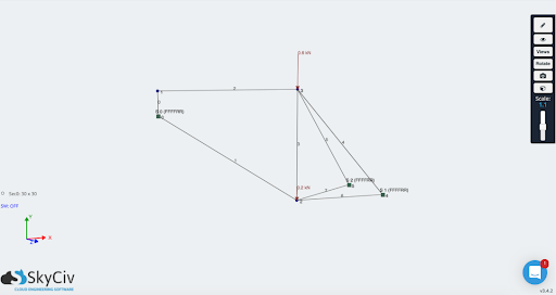
1D modelling approaches are used for modelling line-type members such as columns / piers, beams or piles. Representation of the line is self defined by the user via a section and all geometric properties of the member (width, height, etc.).
Meshing
As meshing is a crucial step in any structural analysis, it is important that users are aware of the impact that meshing plays on 1D, 2D, and 3D elements on a model.
As mentioned before, 1D elements are commonly used to represent line members and can provide accurate bending behaviour of a member. 1D element meshing is the division of the member into multiple segments, this does not affect the overall result but more segments allows smoother and better visualization of the results.
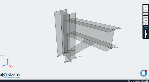
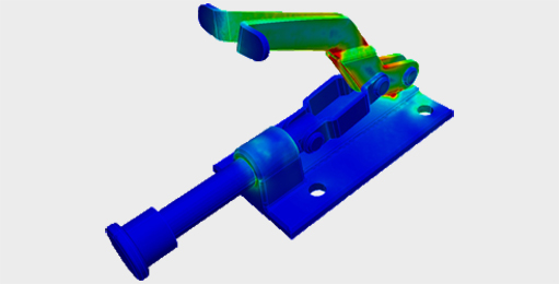
2D and 3D elements present similar traits in terms of meshing. Each member inside the model is divided into multiple parts of a certain shape, the mesh size of the model affects the final results and that the finer the mesh (smaller shapes used) the longer the time taken to solve the model. There are two shapes that are used for both 2D elements in meshing, quadrilateral and triangular elements. 3D elements shapes are variations that stem from the 2D element shapes, commonly used shapes are hexahedrons, tetrahedrons, wedges and pyramids with each offering different benefits to better model the physics of the model itself.
Output (post-processing)
The analysis results for members modelled using 1D elements are usually given in terms of shear force and bending moment about the two main axes of the members as well as axial force and torsional moment about the axis that connects both ends of the member.
-
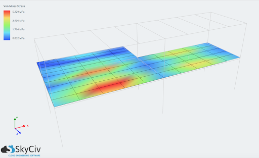
- Membrane forces
- Shear/moment forces in plane
- Displacements (x,y,z, sum)
- Shear (Von-mises, direct, shear, major/minor principal)
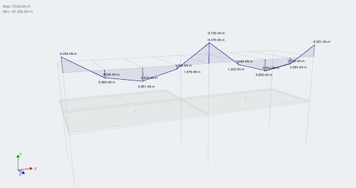
When, brick elements are adopted, the results are given in terms of stresses. Therefore, the internal forces and support reactions of members like shear walls, shells or slabs modelled using 2D elements or brick elements is obtained through integration of internal forces/moments per unit length or stresses over the length or area of interest, respectively.

CTO and Co-Founder of SkyCiv
BEng Mechanical (Hons1), BCom