So you’ve tried 3D analysis software before and ended up feeling frustrated by the user interface and mind-boggled by all the features? Well, if that describes you, then you’re in for a treat!
The purpose of this tutorial is to give you a quick-start guide to get you up and running quickly with SkyCiv, software that has been designed specifically with ease of use in mind. This step-by-step tutorial leaves nothing out, so if you have either never come across SkyCiv, or you have tried it but got nowhere, then this is the tutorial for you.
And as an additional helping hand, the companion video course takes you through the whole process of modelling, analysing and carrying out the structural steel checks on this project. You can enrol totally free here: SkyCiv Structural 3D - Quickstart Tutorial.
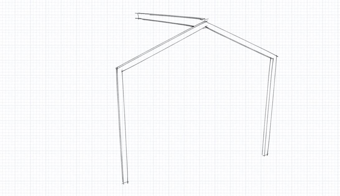
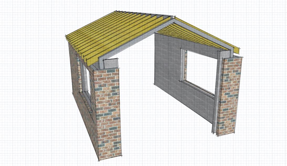
Now, if we’re going to start at the beginning of our learning journey, then we need something small and manageable as an example project so that you can get a quick win under your belt. With that in mind, we’ll design this steel gable frame and ridge beam. It’s both simple to model, and also has a simple loading, whilst also being useful as a real-world project:
Once you have gone through this tutorial, you should be feeling ready to tackle much larger and more complex projects.
Modelling the structure
In this first part, you will model the nodes and members you will need to model the structure. A node is simply a point in space to which a member can be attached. A member is simply a line in space attached to two nodes. Simple!
Go to Analysis Software > Structural 3D, and select the Start New button.
On the menu bar on the left hand side, select Nodes.
You will now enter the x and y value for each node that you wish to create. X relates to the x axis, which is the Red direction, and Y relates to the y axis, which is the Green direction:
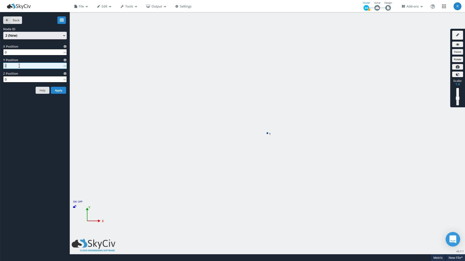
Enter “0” for X Position, and “0” for Y Position, and hit Apply. You will see node number one appear as a dot in the canvas area as you can see in the above image.
Now continue and add the following four nodes to complete the gable frame:
X = 0, Y = 2.5
X = 5, Y = 0
X = 5, Y = 2.5
X = 2.5, Y = 3.5
You should now have the following on your screen:

Now click Back in the menu area, and select Members.
Select all the following:
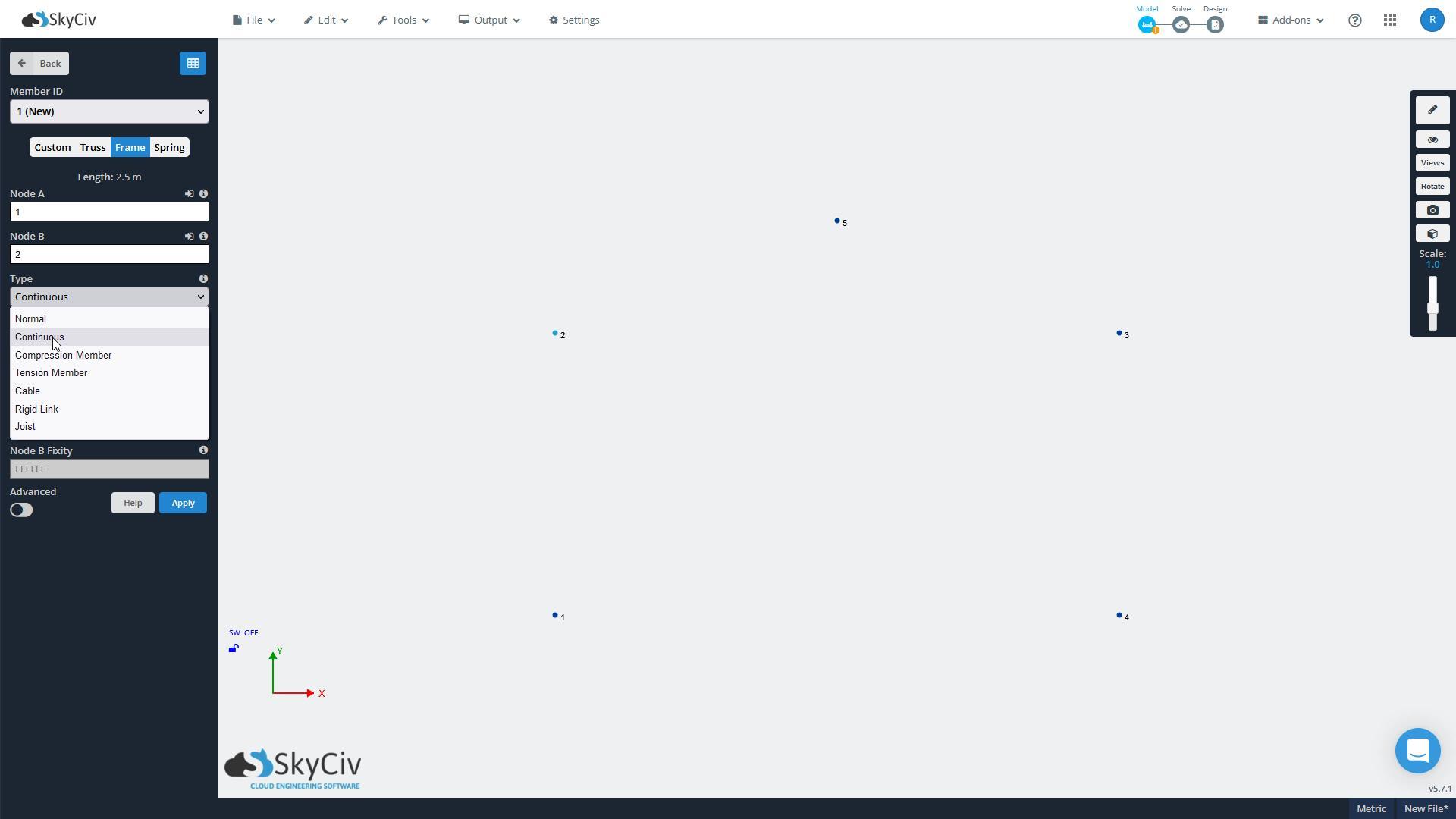
By typing in “1” for Node A, and “2” for Node B, you are telling SkyCiv to draw a line from Node 1 to Node 2. This line is called a Member, and will become the left hand post of the steel gable frame. Selecting Frame will ensure that the ends of the member are fully fixed, which we need it to be because it is going to be welded to the slanted member.
Continue with this by drawing in members from nodes 2-5, 5-3, and 3-4. All you’re doing is joining up the dots! You should have the following once you’re done:
Notice that the members are now all numbered too. We have members 1, 2, 3 and 4, as well as the five nodes.
Adding supports
Now it’s time to support the bottom of each column. A support is a fixed point in space that will not move. In this case we’re pretending that the supports are the foundation.
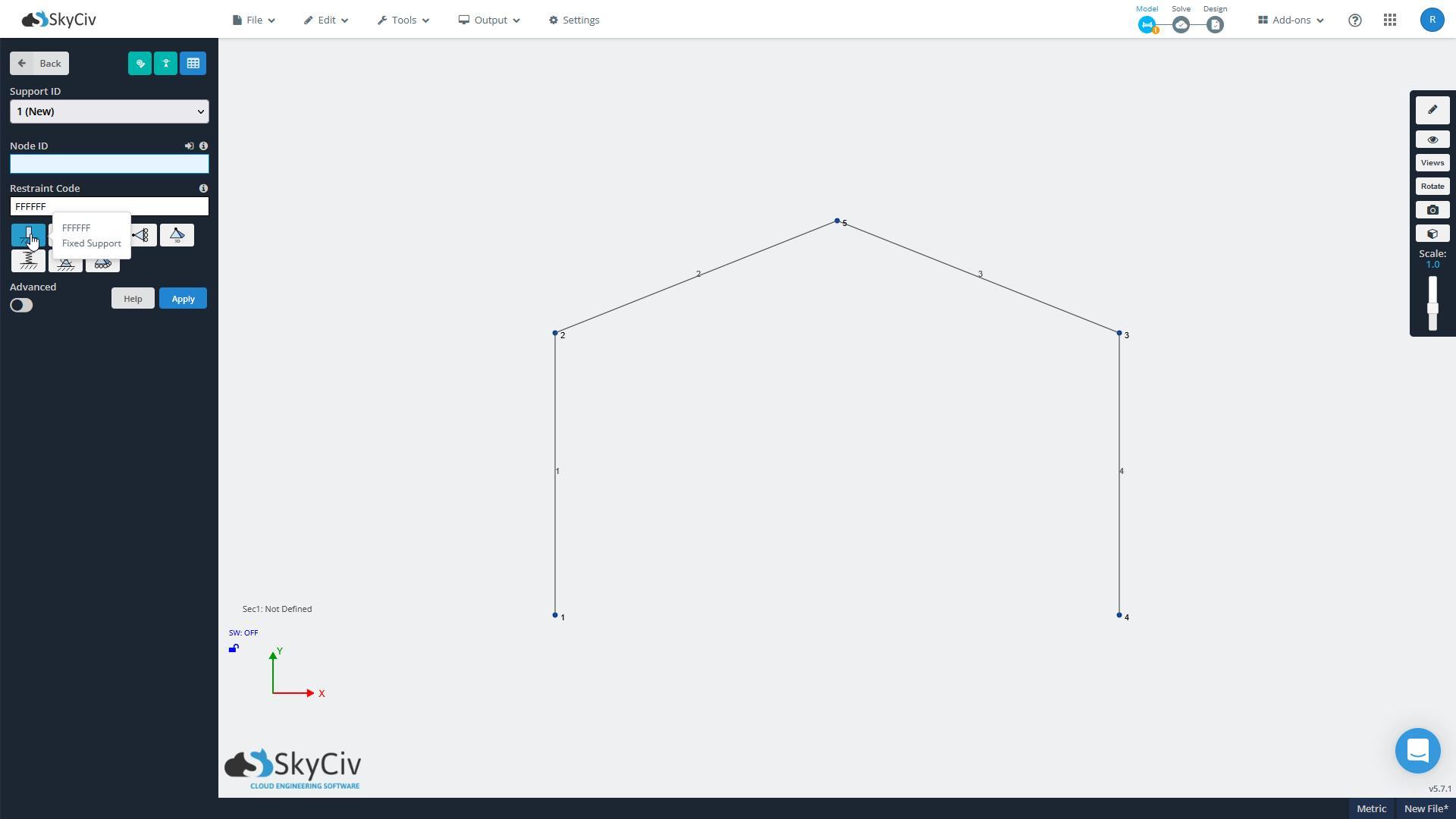
Select Back and go to Supports. Now click in the box labelled Node ID and enter “1,4”. This selects the nodes 1 and 4, which is where we want the bases to be.
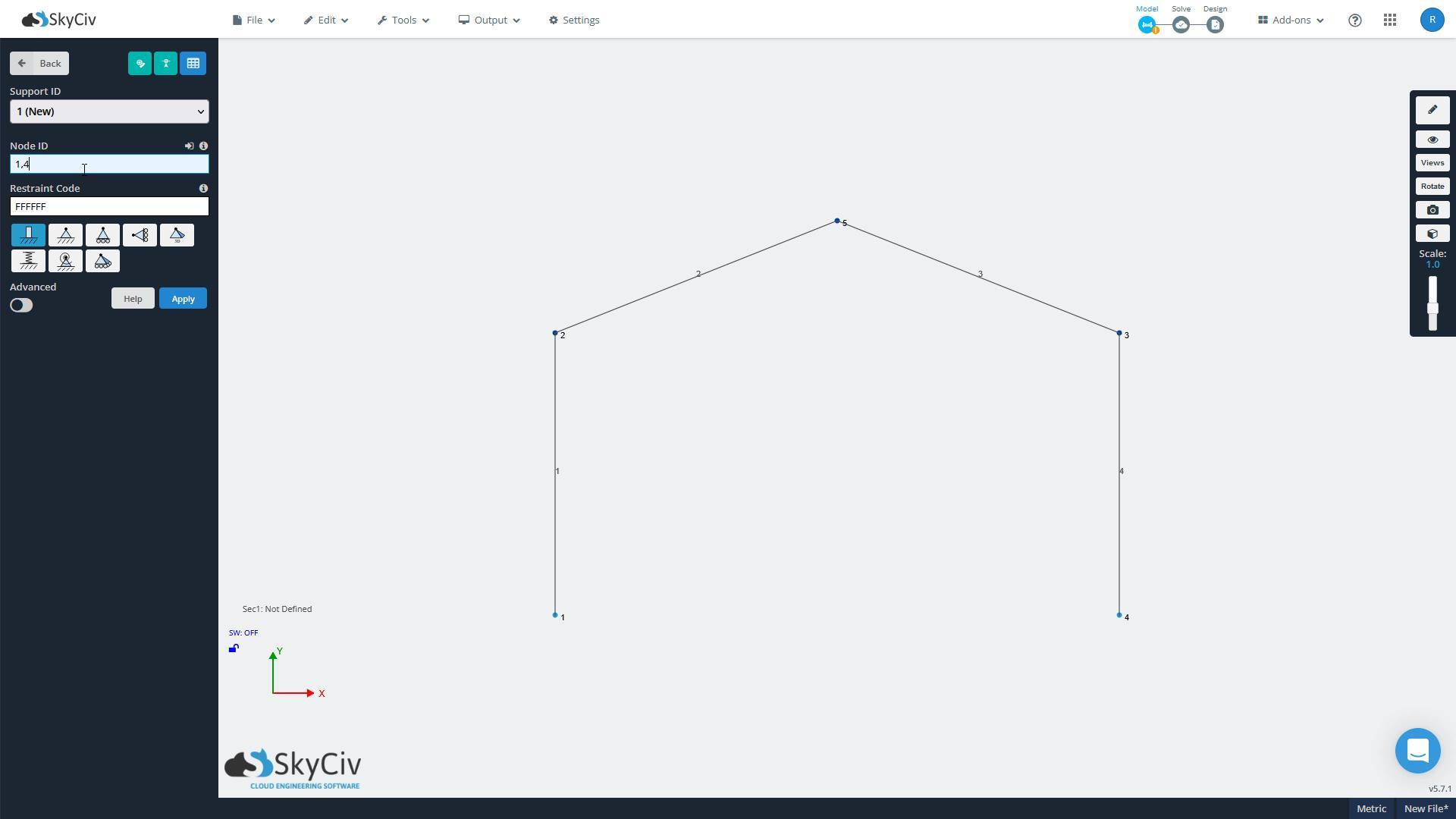
Select the Fixed base (the one highlighted in the image above) and hit Apply. The bases should now appear at nodes 1 and 4 in the drawing canvas.
Don’t forget you can follow along with me in the video I have made of this whole process, by going to SkyCiv Structural 3D - Quickstart Tutorial.
Setting up materials and section sizes
Now hit Back and go to Materials. Select Structural Steel from the box labelled Material ID. Hit Enter.
Hit Back and go to Sections. Select the box labelled Name and type in “Frame”.
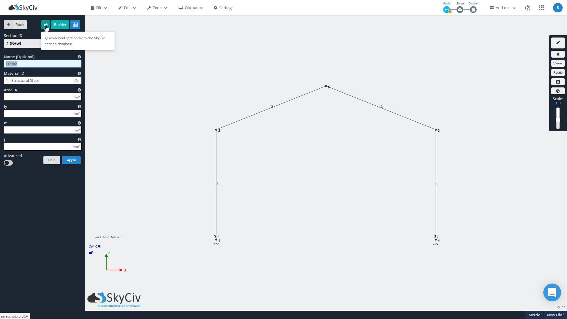
Now select the green button on the left to load a section from the library, as you can see in the above image.
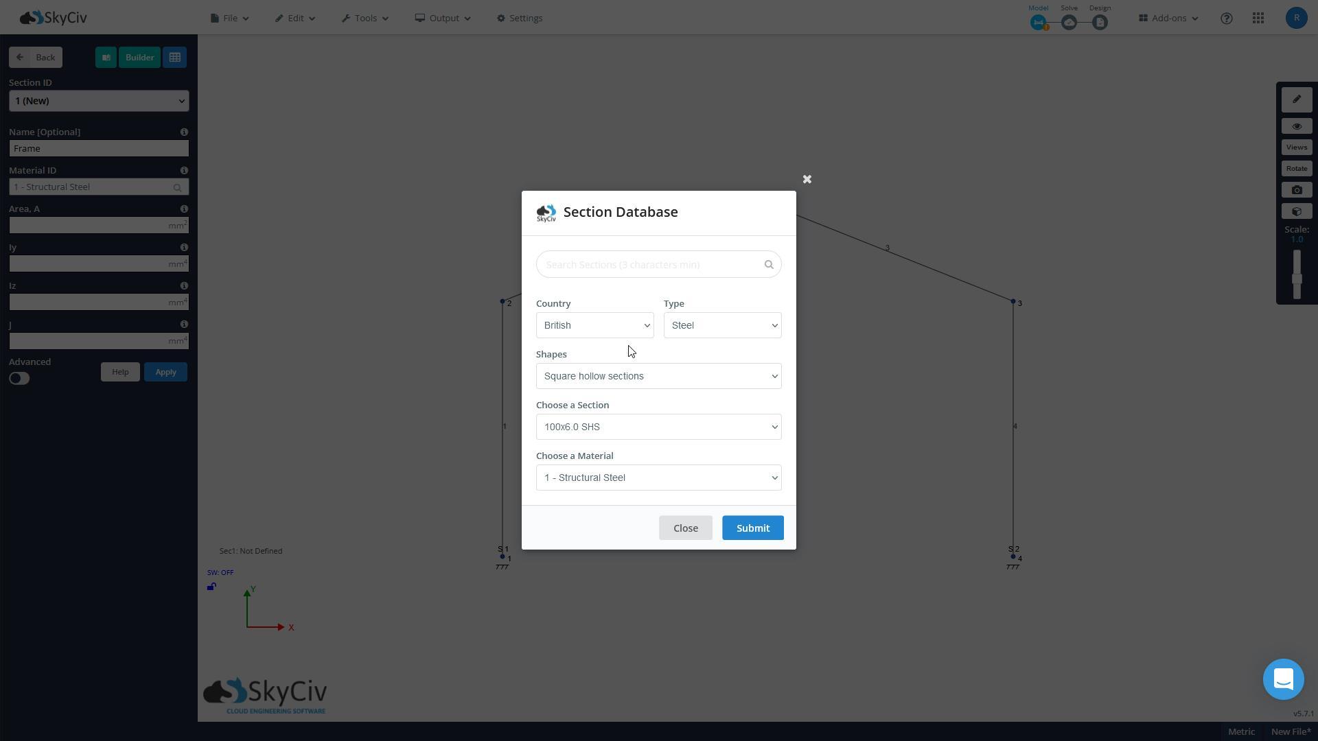
The Section Database will appear. Select the following values and hit Submit:
Assigning steel sections to members
Now to apply this steel shape to the members we have already drawn. Remember, all we have at the moment is a bunch of dots (Nodes) and lines (Members) and fixed points (Bases). We need to tell SkyCiv what the members are made of.
Hit Back and go to Members. Now click on one of the members, hold down CTRL and select the three others also. All the members should now be highlighted in blue, and the menu area should say “Multi-Edit Members” as shown below. Select Section ID “1”, and you should see the 100x6.0 SHS section appear in the Section ID box:
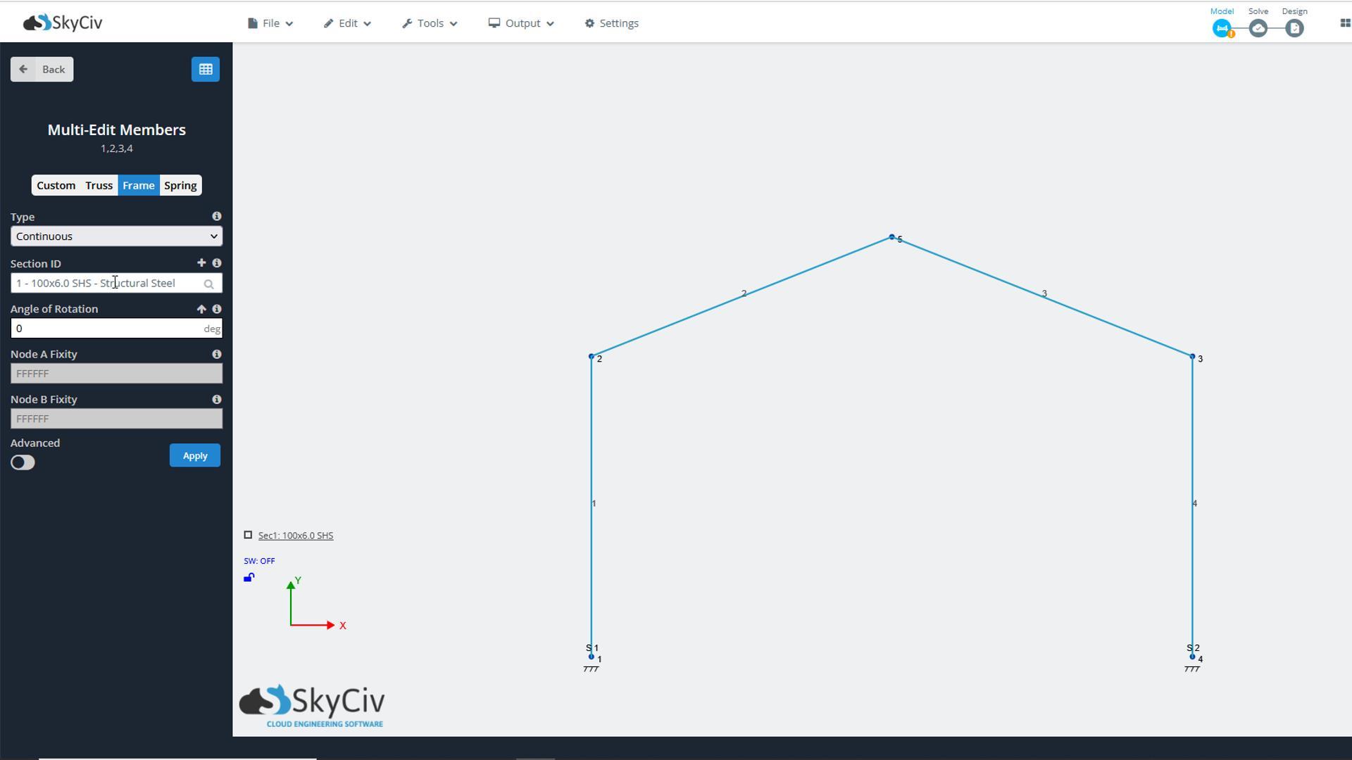
When you click Apply, you should get a dialog box asking you if you wish to edit multiple members. Click Yes.
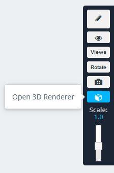
Nothing seems to happen, which may leave you wondering whether anything has changed. So I recommend at this stage to take a look at the rendered view to see what the frame now looks like. To do this, go to the view toolbar at the right hand side of the screen, and select Open 3D Renderer.
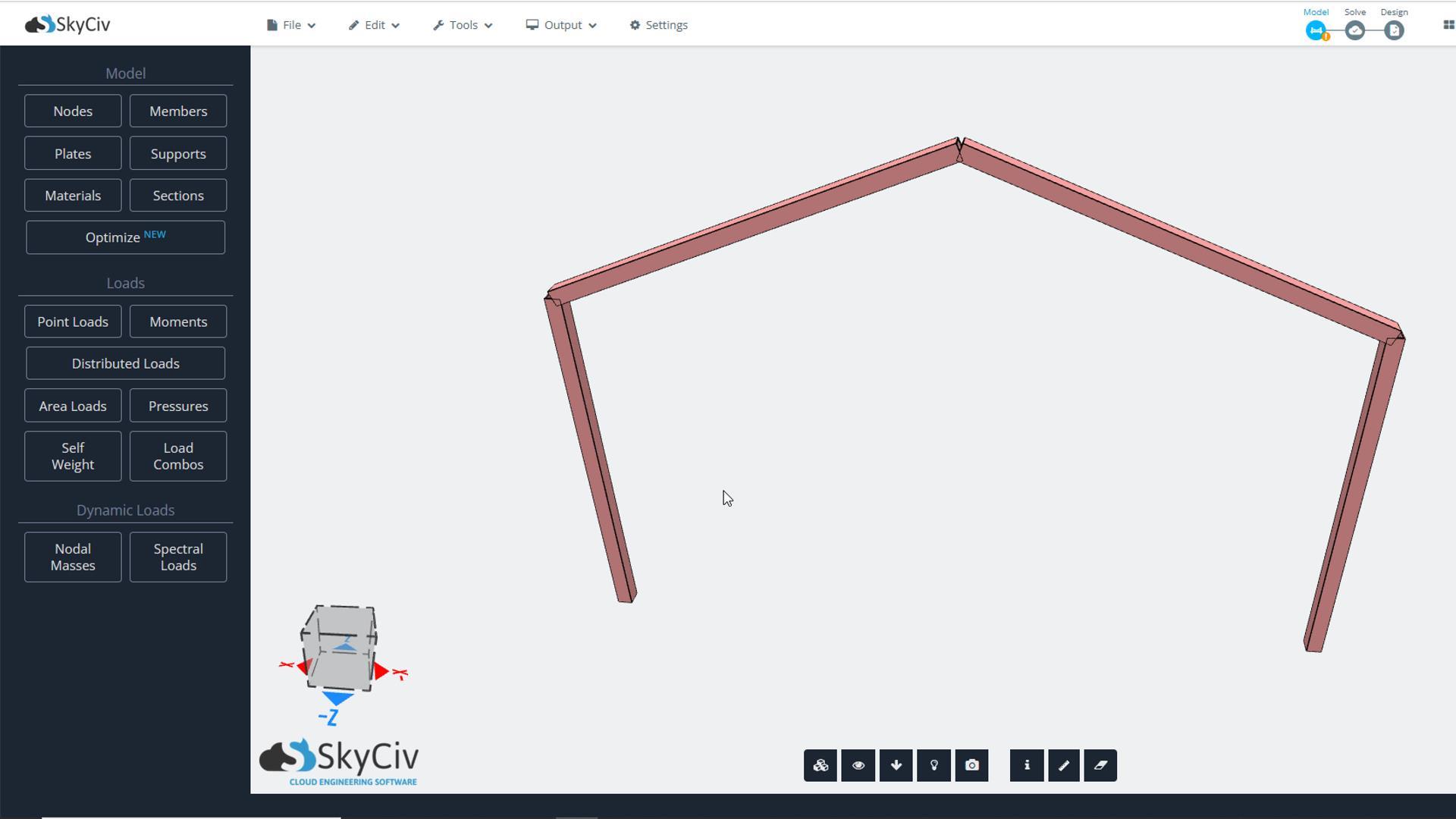
You will now see the following view. Rotate by holding the left mouse button and moving the mouse side to side. Pan by holding the right hand mouse button.
Checking the model deflection
Whenever you have created a frame, it is a good idea to check if you’ve forgotten anything, by seeing if it behaves as you expect. The way I do this is to look at the deflection, also known as “displacement”, of the frame.
To do this, first ensure that SkyCiv is taking into account the self-weight of the steel frame. Do this by going to Self Weight, switching the toggle to ON, and hitting Apply.
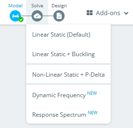
Now that SkyCiv is detecting the weight of the frame, go to the top menu bar and select Solve > Linear Static.
The analysis results menu appears. Click on Displacement and take a look at the deflected form of the frame. This is an exaggerated form of the frame shown in black lines, with the original position of the frame in grey lines.
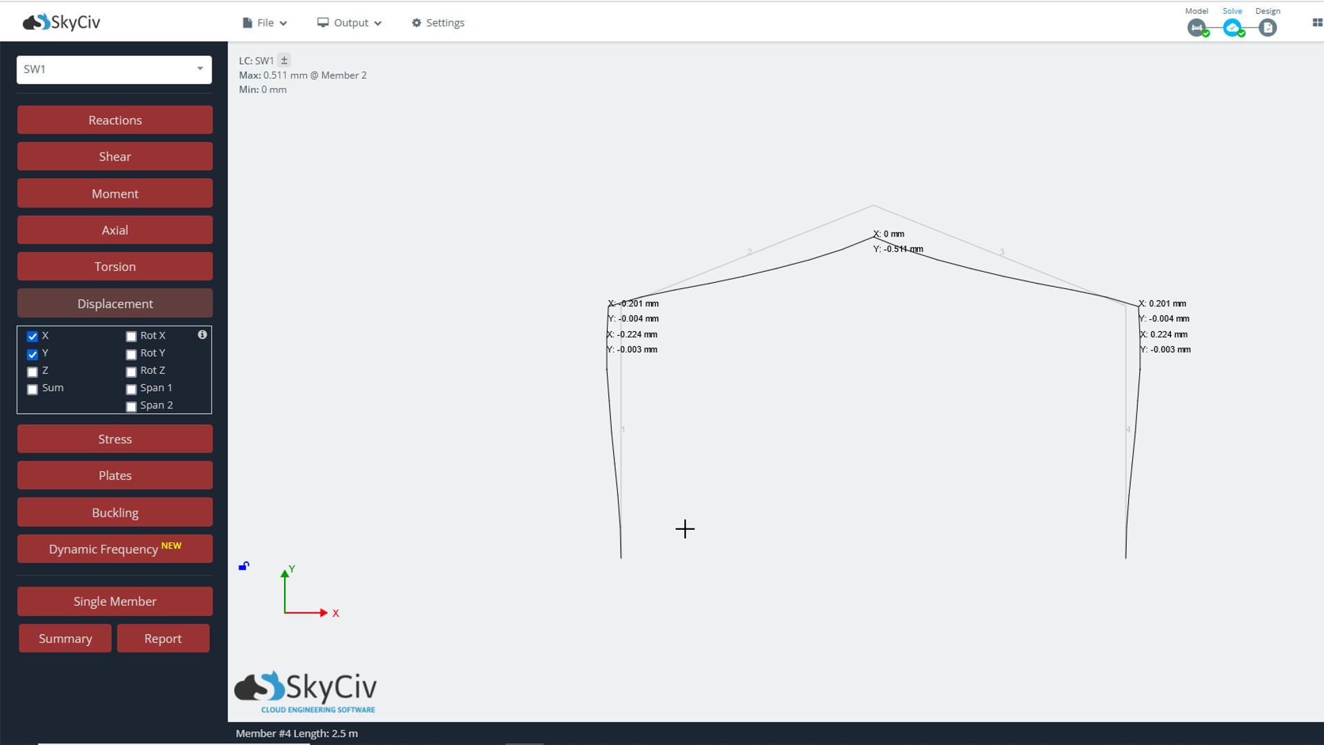
Notice that as the pitched part of the frame sags under its weight, the columns are pushed out sideways and bend to resist this sideways thrust. If it all looks ok, select the Model icon again to go back to the Modelling menus.
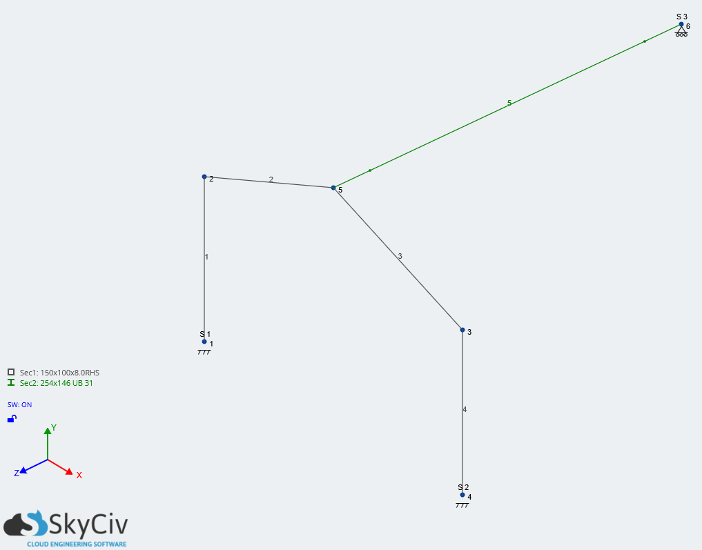
The last task for you to do in this tutorial is to model the ridge beam and the support at the point where it rests on the house wall, and then to apply a new section size to it of a 254x146x31UB. Use the preceding tutorial as a guide, and if you get stuck, don’t forget to enrol for the full video course which covers this step and goes on to show how to add loads and complete the analysis and steel member design.

Robin de Jongh is a Chartered Civil Engineer and is a Director at Woodland Consulting, a structural engineering practice in the UK. He presents a popular youtube channel helping to demystify building structure for builders, architects, and homeowners.
YouTube