When you’re designing a structure to support a slab, it’s important to consider how the slab transmits its load to the structural members. This is generally defined by the slab's tributary area. Tributary area explains how much of the slab is being supported by a particular beam.
In your model, you might consider adding a plate element to model the slab. However, when considering the adequacy of your beams, joists, and girders, this may not be appropriate. When loads are transferred from plate to nodes (no mid-member interaction), unwanted stiffness may be introduced to your model.
Instead, a more appropriate approach would be to consider what is known as an “area load” or “tributary load". This involves converting a pressure load (which acts along a surface) to a distributed load that acts on the beams, joists, and girders. These members support the surface.
In this article, we’ll explore two examples of how this can be done. Mathematically, the calculation for the distributed load is simply expressed as:
[math]\begin{equation}
w=qt_w
\end{equation}[math]
Where w is distributed/area load magnitude, q is pressure load magnitude, and tw is tributary width. Tributary width is the width of an area divided according to the area load type.
The consideration at this point is to determine whether a system is one-way or two-way, allowing the tributary width and load distribution to be assigned to the member. In general, if the load from the slab is delivered to the beams in one direction, then the system is one-way. Conversely, if the load is delivered to the beams and the girders in two directions, then the system is considered two-way.
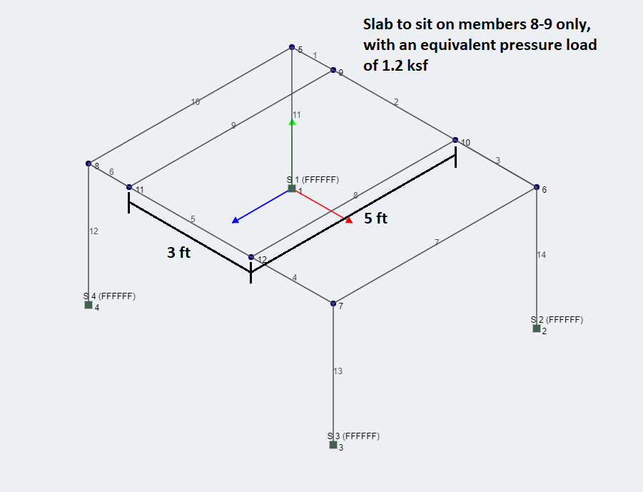
Example: One-Way System
In this example, the pressure load from the slab is transferred directly to the beams. Since the girders are not directly supporting the slab, the system is considered one-way. The area load is thus calculated as:
[math]\begin{equation}
w=qt_w=1.2 \times 3/2=1.8 kip / ft
\end{equation}[math]
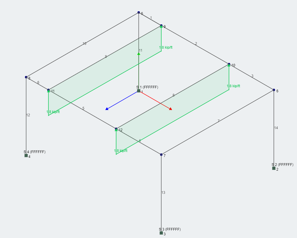
A one-way system will divide up the area formed by the two members selected. In this example, since it is a rectangle, the profile of the area load is also rectangular as shown below. Note that the profile is not always rectangular, but rather it is always quadrilateral and represents an equal division of area between the two members. In some cases, point loads are added in order to force balance the system if the slab overhangs the member.
Two-Way System
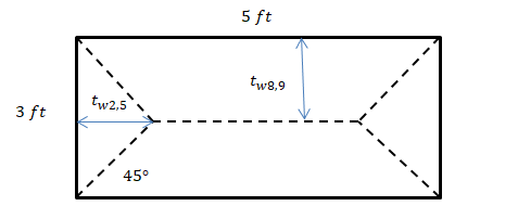
For the same structure as the previous example, if the slab were to instead be directly supported by members 2,8,5,9 then the system would be considered two-way. The slab occupies the same area as the previous question, however the load profile will change. For two-way systems, bisecting lines are drawn from the corners to create a pair of triangles and a pair of quadrilaterals as shown in the diagram below:
Thus, the calculation for area load for members 8 and 9 is given by:
[math]\begin{equation}
w=qt_w=1.2 \times 3/2=1.8 kip / ft
\end{equation}[math]
And for members 2 and 5 (by simple trigonometry),
[math]\begin{equation}
w=qt_w=1.2 \times 1.5\tan(45^\circ)=1.8 kip / ft
\end{equation}[math]
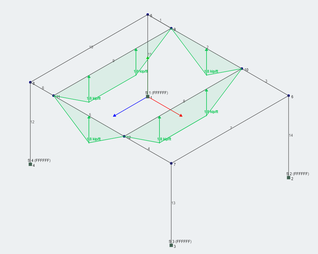
Applying these area loads to the structure is shown below:
Through these examples, we've examined the two type of area loads. To learn more about SkyCiv's implementation of this feature, check out our area load documentation here.
William Kuang
Engineer and Software Developer BEng Mechanical (Hons1) LinkedIn
Unlock your Free Account
Register for a free account and get access to powerful analysis + design software:
 Through these examples, we've examined the two type of area loads. To learn more about SkyCiv's implementation of this feature, check out our area load documentation here.