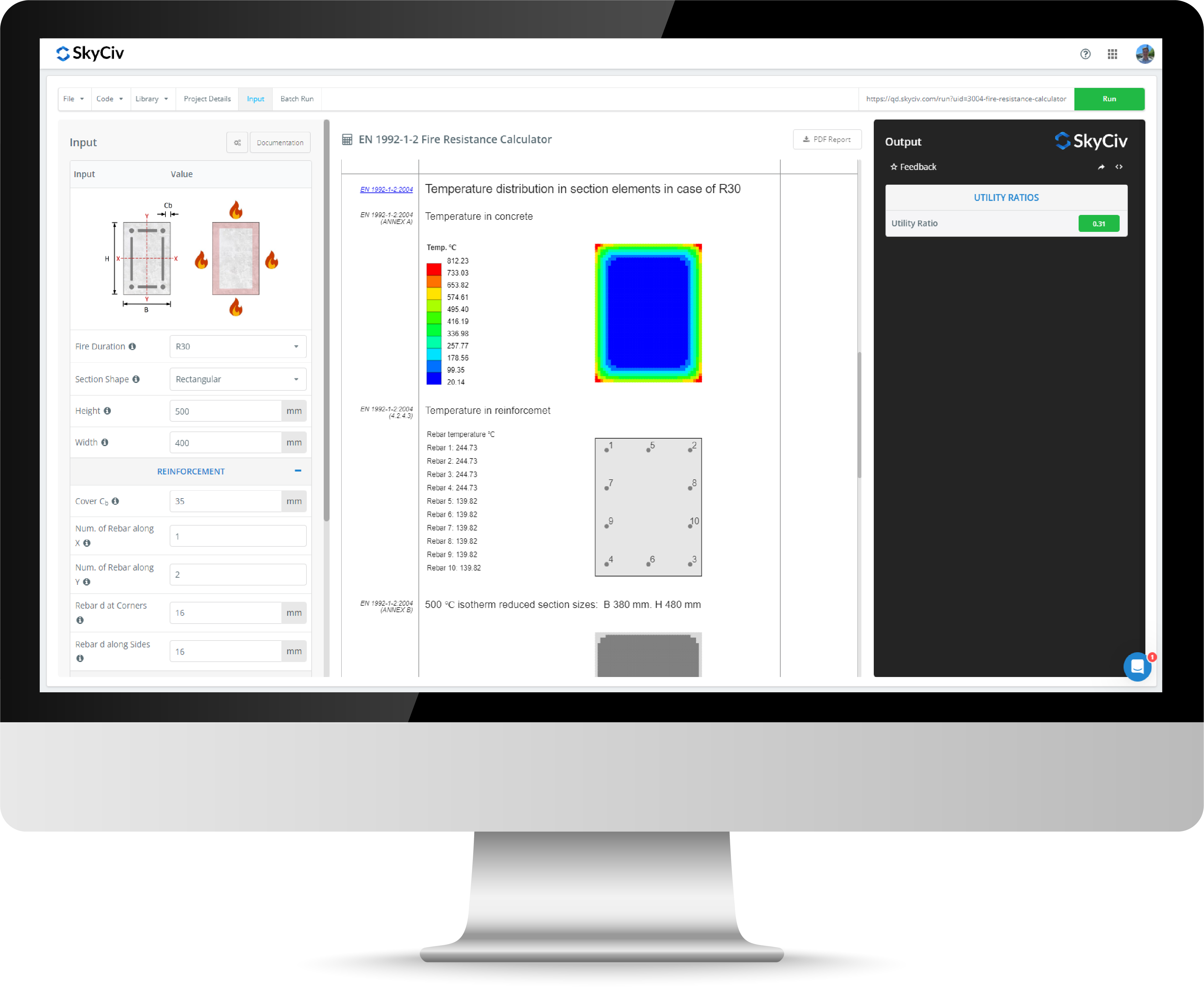
AS 1720 Wood Connection Calculator
The SkyCiv AS 1720:2010 Wood Connection Calculator is designed to aid structural engineers in the calculation of timber joint capacities for different fasteners in accordance with the AS1720. The tool supports all joint groups for seasoned and unseasoned timber as defined in the AS 1720:2010. The below tool includes the following fastener applications:
- Nail Connection Calculator
- Screw Connection Calculator
- Bolt Connection Calculator
- Coach Screw Calculator
This tool carries out a comprehensive check of the fastener shear capacity (type 1 connection) and fastener withdrawal capacity (type 2 connection) for different load orientations with respect the the grain of the timber member in a joint.
The calculation results have been verified against the SA HB 108 Timber Design Handbook to ensure its validity.
For full timber and structural analysis, pair this tool with SkyCiv's Timber Design Software.
About the AS1720 Wood Connection Calculator
What Does the Wood Connection Calculator Do?
The SkyCiv Wood Connection Calculator allows users to design both connections in shear (type 1 connections) or connections in withdrawal (type 2 connections).
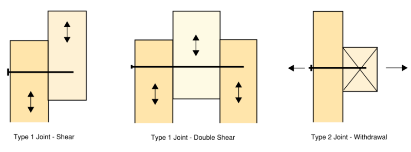
A user can simply select the fastener type and load type from a dropdown in the Arrangement drop down menu to get to one of 12 different possible connections. This will then simplify remaining inputs such as the timber dimensions, joint group, and fastener size so a user can quickly and easily design the connection.
How is Connection Capacity Calculated in the AS 1720:2010?
The AS 1720:2010 Section 4 covers the design capacity of joints in timber structures. Joint groups are used to group different timber species into categories and simplify design. Joint groups labelled JD1 through JD6 for seasoned timber and J1 through J6 for unseasoned timber are not to be confused with strength groups which are used for member design.
The design capacity of joints (Rd) can be generalised to the following equation:
Rd = φ * kmod * n * Q
where:
- φ = Capacity factor
- kmod = Product of modification factors (k1 * k ... * kn)
- n = Number of fasteners
- Q = Characteristic capacity of the fastener (dependent on joint arrangement )
Common modification factors used in the design of type 1 and type 2 connections are:
- k1 - Factor for duration of load for joints
- k7 - Factor for length of bearing
- k13 - Factor for end grain effects
- k14 - Factor for effect of double shear
- k16 - Factor for plywood or metal side plates
- k17 - Factor for multiple fastener effect
The factors often have slight differences in values and consideration for different fastener types, which is automatically handled by the SkyCiv Wood Connection Calculator.
How to Design a Timber Screw Connection
Screw Shear capacity can be calculated by selecting "Screw" in the fastener type dropdown menu and then selecting either the "Shear" or "Double-Shear" option in the load type dropdown.
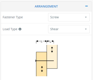
Connection geometry properties are required to determine if minimum embedment requirements have been met or if a reduction on the characteristic capacity needs to be applied.
The capacity can then be calculated using the modification factors and the characteristic capacity of the screw which is dependent on the screw size, timber joint group and screw embedment length.
Similarly, screw withdrawal strength can be calculated by selecting "Screw" in the fastener type dropdown menu and then selecting the "withdrawal" option in the load type dropdown.
How to Design a Timber Nail Connection
Nail shear capacity and nail pullout capacity can be calculated the same way as screws except for changing the dropdown to "Nail" for the fastener type.
The main difference between nails and screws is in withdrawal capacity due to the different mechanics of the fastener. The HB 108 found similiar sized screws to be only 10% stronger than nails in shear but 300% stronger then nails in withdrawal.
To help increase withdrawal capacity nails may be skewed which is considered in the SkyCiv Wood Connection Calculator.
How to Design a Wood Bolted Connection
Bolt shear capacity can be calculated by selecting "bolt" in the fastener type dropdown menu and then selecting either the "Shear" or "Double-Shear" option in the load type dropdown.
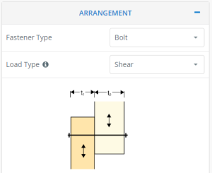
Bolted connections differ from screws and nails in that there installation requires the removal of timber material in order be installed. As a result of this mechanical difference bolt capacity is dependent on the direction of the load with relation to the grain of timber.
The SkyCiv Wood Connection Design Calculator allows for a flexible method to define the load direction independently for the inner and outer members in the joint.
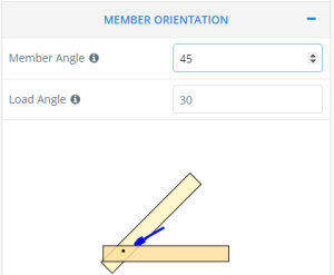
Bolt shear capacity can then be calculated with a formula similar to that for screw and nail connections.
Bolt withdrawal capacity can be calculated by selecting "bolt" in the fastener type dropdown menu and then selecting the "withdrawal" option in the load type dropdown.
Bolt withdrawal capacity involves a different mechanism to that of nails, screws and coach screws in that bearing is applied to the face of timber. As a result the capacity of a bolt in pullout depends on the size of washer and its bearing area on the timber face as well as the k7 parameter which increases bearing strength for bearing away from the edge/end of a timber member.
How to Design a Wood Coach Screw Connection
Coach screw shear capacity can be calculated by selecting "Coach Screw" in the fastener type dropdown menu and then selecting either the "Shear" or "Double-Shear" option in the load type dropdown.
Coach screws shear capacity design is largely the same as bolt shear capacity design with a few minor additional compliance requirements laid out in the AS1720:2010.
The main difference between a coach screw and a bolt is the mechanism of resistance to type 2 (withdrawal) loads, which is reflected in the capacity calculations and the magnitudes of strength that can be achieved by the different fasteners.
A coach screw may be used where it is geometrically infeasible to install a bolt.
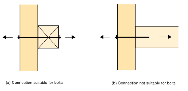
In general, a bolt would be expected to provide a larger capacity than an equivalent coach screw which is reflected in the upper bound axial capacities of bolts given in Table 4.11, and the upper bound axial capacity of coach screws given in Table 4.14.
Wood Connection Calculator FAQs
What inputs are required?
The AS 1720 Wood Connection Calculator has the following inputs:
- Arrangement: Fastener type and loading type
- Member Orientation: For orientation of load to timber grain in bolted connections
- Connection Geometry: Effective width of timber, embedded of fasteners and number of fasteners
- Fastener Details: Size of fastener and related details specific to fastener types
- Timber Properties: Joint group for characteristic strength calculations
- Loading and Duration: For capacity factor and utilisation calculation
What results are provided?
The AS 1720 Wood Connection Calculator provides the following outputs:
- Characteristic strength of fastener
- Shear capacity for type 1 connections
- Withdrawal capacity for type 2 connections
- Minimum spacing, edge and end distances
What assumptions / limitations does the calculator have?
The AS 1720 Wood Connection calculator has the following assumptions and limitations:
- This tool does not carry out serviceability or deflection checks. All checks are for ultimate limit state only.
- This tool does not support the design of fasteners connected closer than the required spacings of the AS1720:2010.
- This tool does not support combined actions for fasteners.
- Fastener shank diameters are assumed to be consistent with shank diameters given in the AS1720:2010. No consideration for rusty or defective fasteners is made.
- The calculator does not consider any eccentricity effects that may result when members meeting at a joint are not arranged symmetrically.
- The calculator assumes that the minimum sized washer required by the AS 1720 table 4.11 is used for bolts and coach screws where required.
Related Tools
About SkyCiv
SkyCiv offers a wide range of Cloud Structural Analysis and Design Software for engineers. As a constantly evolving tech company, we're committed to innovating and challenging existing workflows to save engineers time in their work processes and designs.

