Simple Timber Design Model
This tutorial helps walk you through the basics of using SkyCiv to model 3D timber structures. We cover modeling the structure, adding supports and loads, designing the member section, and eventually analyzing the model and generating a report.
If you are looking to use SkyCiv to model a wood or timber structure, this is the best place to start!
Introduction
The following tutorial will walk you through how to design a Timber Structure using SkyCiv Structural Analysis Software. We will cover how to best model the structure, perform some basic analyses, and additionally cover some specific topics such as load combinations, fixities, section builder, and assemblies.
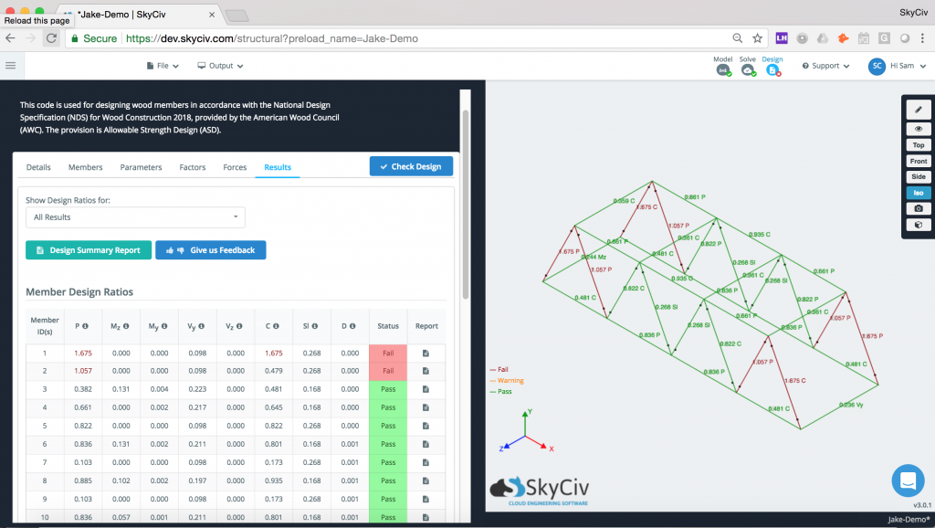
Your first step will be to navigate SkyCiv Structural 3D and starting a new project. Once you have set up your desired project standards in the Settings menu you are ready to get started.
Nodes & Members
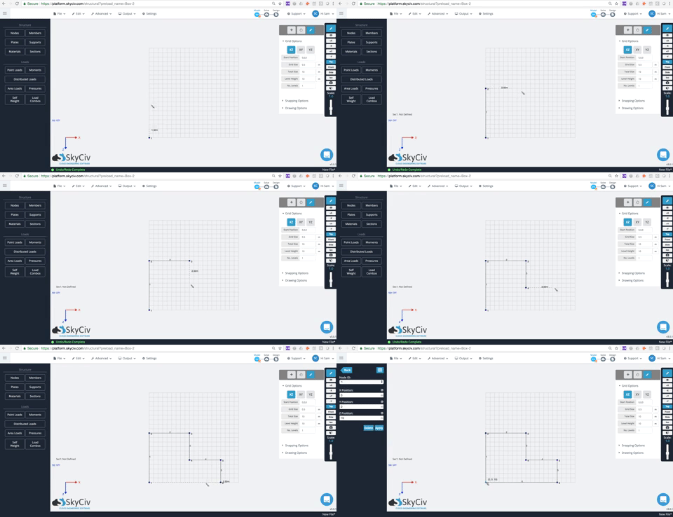
In SkyCiv 3D, all structures are made up of nodes and members. You can specify nodes by inputting their x,y, and z coordinates directly into the datasheet form. Additionally, you can draw nodes with the Pen Tool to lay them out specifically where you would like them placed.
Once you have laid out your nodes, next you can draw your members. Again, you can use the datasheet to define the starting and ending nodes of a member. Additionally, using your mouse, you can drag to draw a member from node to node to specify where you would like it to be.
Defining Material and Sections
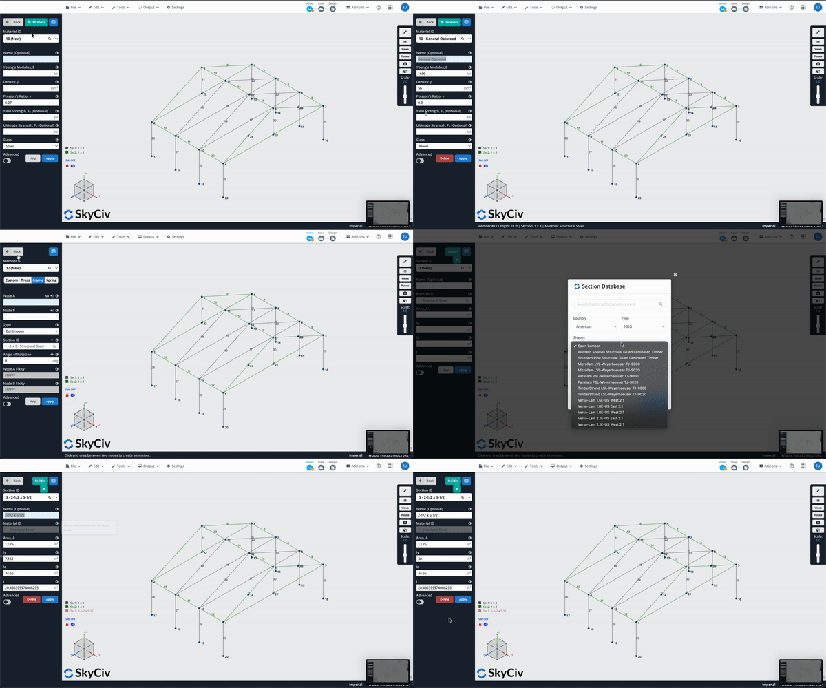
Now that you have drawn out your basic structure with its nodes and members, the next step in the process is to modify the material and section properties. Each member will need to have a section number assigned to it. By selecting “Sections” in the left hand menu, an option will come up to define new sections. You can select a default section from the drop down menu or enter the “Section Builder” module to fine tune the design. Once your values have been defined and material has been selected, you must assign a section to each member in your model.
Loading NDS Material Data
Once you have defined your section, the next step is to load the right material data for wood into your project. Select the value from the available material library or edit the values yourself based on material data as shown in the video below. Once that is done, you have completed selecting the right wood for your timber structure!
Customizing Section Using Section Builder
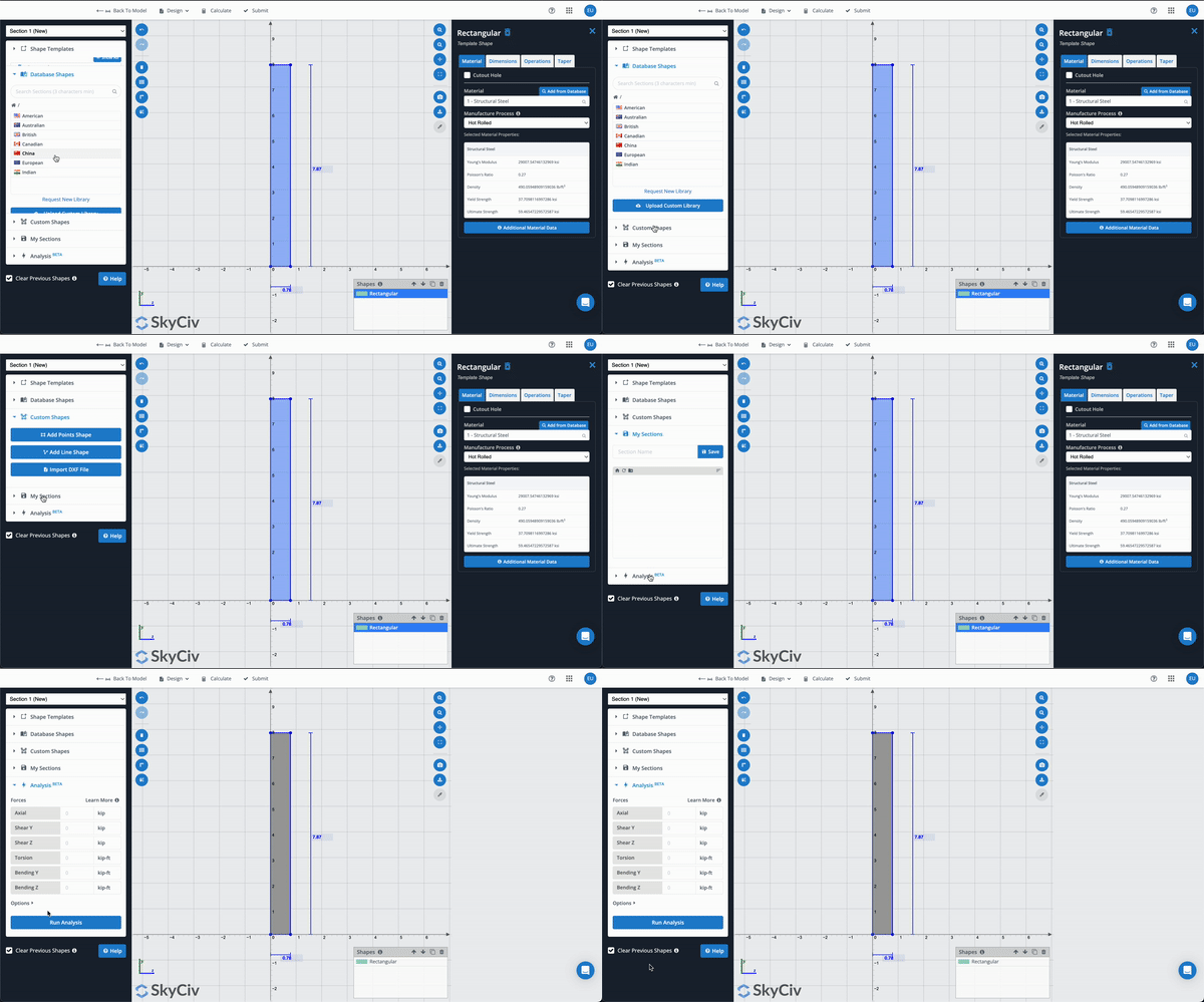
Sometimes you want to define a unique shape for your section or slightly modify the geometry of the section yourself. Under section builder, you have the ability to make these changes as well as modify the material data information you input from the previous step to fine-tune your design perfectly. Once you are done with this you are ready to move on to the final steps.
Adding Loads & Supports
The final step in our design process is assigning loads and supports. To apply wind or roof live load, you will use the Area Loads feature. This will allow you to apply a distributed load from one node to another with assigned maximum and minimum values. For point loads, just select the node where it will be occurring and the orientation and this will populate the data into the model.
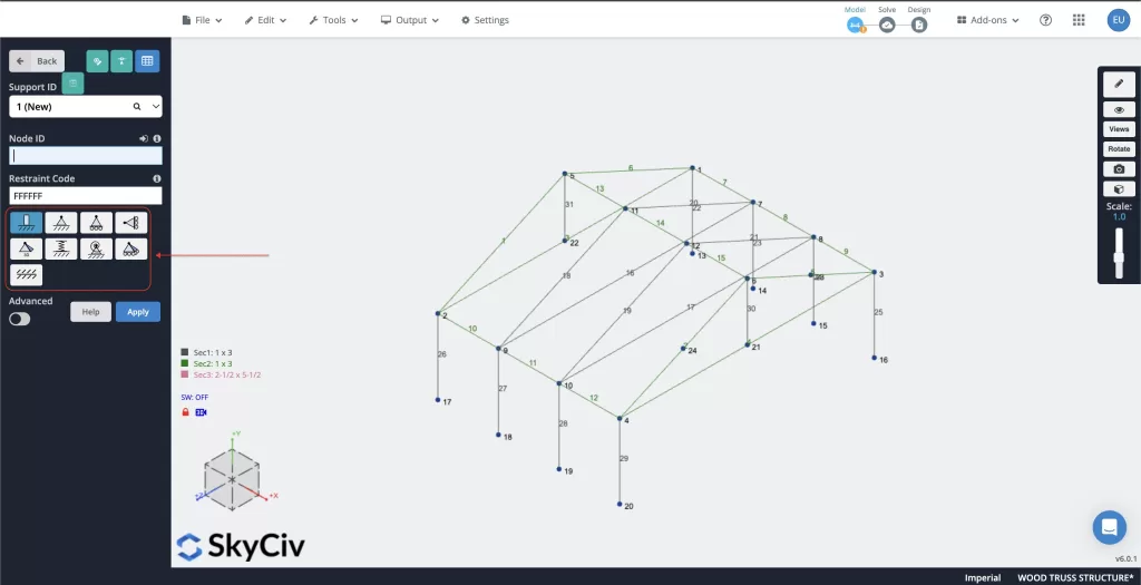
After your loads have been defined, select your nodes occurring on the ground, click on the Supports tab, and then under each Node field select 3D Pin support. There is more information on our documentation site about the various types of supports and how they can impact your structure should you want to modify these further down the road.
Solving Model
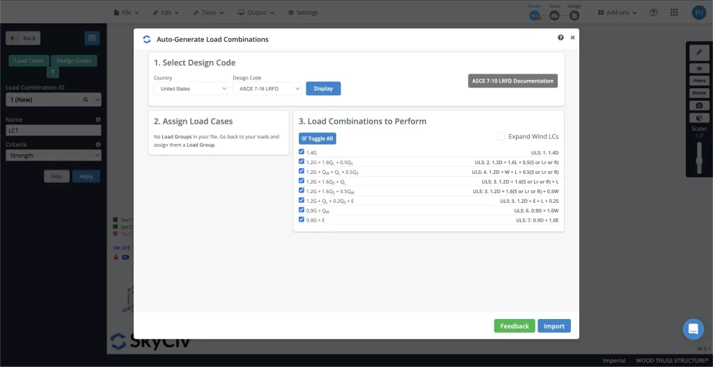
Now as we begin analyzing the structure you will need to import the load combination. For this exercise, as we used US NDS standards, we will use ASCE – 7 LRFD load combinations. Select the Load Combos button on the left and then select Design Codes. When the menu pops up, under “1. Select Design Codes” under the “Design Code” dropdown select ASCE 7-16 LRFD. Select “Display” and once the load combinations populate press “Import”.
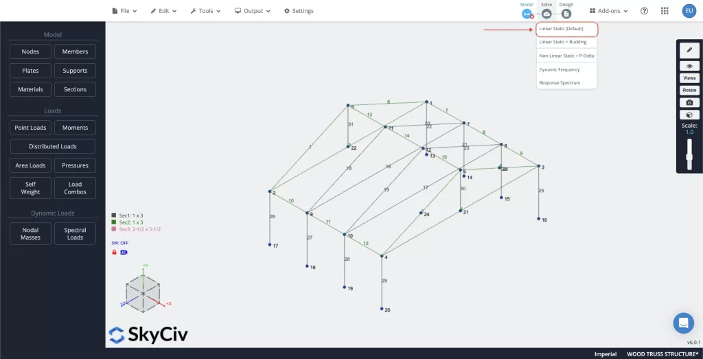
Once this is done, select the “Solve” button in the upper right-hand corner and then select the “Linear Static (Default)” option. Once the model completes solving, you have successfully modeled and solved a Timber Wood Structure using SkyCiv Structural 3D!
Designing Model
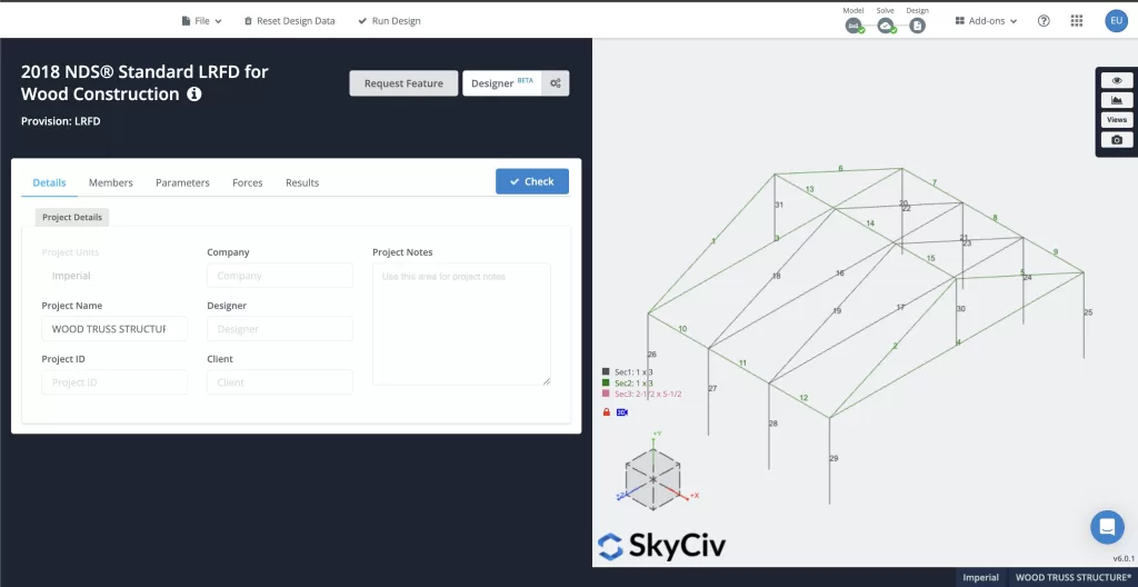
The final step is to design the whole structure. Still in the upper right-hand corner select “Design” and select “Start New Code”. Choose “Member Design” in the first menu and then for the design code choose “NDS 2018 LRFD” for the last menu. Confirm the selection and once the process is completed you will be brought to the final screen with your finalized design. Congratulations, you have successfully designed a Timber Wood Structure using SkyCiv Structural 3D!
FAQ
Yes, you definitely can change those values to better suit the material you are using. While SkyCiv initially populates those values based on default information in our material library, feel free to update that information if, for example, you have more accurate data based on manufacturer specified specifications.
Yes, you can always go back and make updated to your model as necessary even after you have moved onto the “Solve” or “Design” stages. Keep in mind though, that any changes you have made in the subsequent sections will be lost by moving back to a previous step.
Yes! Our documentation site (which features a lot of additional resources) has an example of a Timber Barn Frame which verifies the deflection, forces, moments, and linear analysis with shear area of an NDS timber design using SkyCiv software.

