
Exemplo de design da placa de base usando AISC 360-22 e ACI 318-19
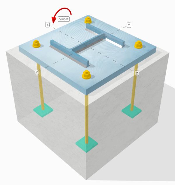
Declaração de problemas
Determinar se a conexão de placa de coluna para base projetada é suficiente para um 5 kip-ft strong-axis moment.
Dados dados
Coluna:
Seção de coluna: W8x31
Área da coluna: 9.130 no2
Material da coluna: A992
Placa Base:
Dimensões da placa de base: 15 em x 15 no
Espessura da placa de base: 1 no
Material da placa de base: A36
Concreto:
Dimensões concretas: 18 em x 18 no
Espessura do concreto: 15 no
Material concreto: 3000 psi
Soldas:
Tamanho da solda: 1/4 no
Classificação de metal de enchimento: E70eixo XX
Carga de compressão transferida apenas através de soldas? NÃO
Modelo na ferramenta gratuita SkyCiv
Modele o design da placa de base acima usando nossa ferramenta online gratuita hoje mesmo! Não é necessária inscrição.
Determine if Low Moment or Large Moment
The calculations for this base plate example, which is subjected to a strong-axis moment, will be based on Guia de projeto AISC 1, 3Edição RD. According to the design guide, base plates subjected to moment loads only are classified as the Large Moment Case. This is because no axial load is present to counteract the eccentric load acting on the connection.
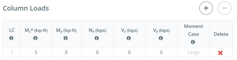
For other load combinations, such as strong-axis bending with axial compression or strong-axis bending with axial tension, determining if the case is Large Moment or Low Moment depends on the actual tamanho da coluna, base plate size, concrete size, and the given cargas.
In the free version of SkyCiv, the moment case is displayed as you enter the load values. You can access the free tool here to determine the moment case yourself. Straight from the browser, nenhuma instalação necessária.
To learn more about Low Moment and Large Moment case, refer to this SkyCiv article: AISC DG1: Placas de base com grande momento e baixo momento
Cálculos passo a passo
Verificar #1: Weld capacity
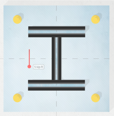
We start the design by checking the weld capacity of the connection. We use the Blodgett equations from Projeto de Estruturas Soldadas por Omer W. Blodgett to determine the weld section modulus of the weld. We take the weld shape shown below as a simplification.
\(S_w = 2d_{col}b_f + \dfrac{(d_{col})^2}{3} = 2 \times 8 \text{ in} \times 8 \text{ in} + \dfrac{(8 \text{ in})^2}{3} = 149.33 \text{ in}^2\)
A continuação, we divide the applied bending moment by the weld section modulus to determine the weld stress per unit length. Note that in calculating the weld section modulus, we assume the critical weld stresses occur at the outermost fiber. For a weld in an I-shaped section, the critical locations are at the outer flanges. We get the weld stress as:
\(r_{uw} = \dfrac{M_z}{S_w} = \dfrac{5 \text{ kip·ft}}{149.33 \text{ in}^2} = 0.40179 \text{ kip/in}\)
Então, nós calculamos o capacity of the weld. Para 0.25 in weld size, the design weld throat is 0.177 no, which is obtained by multiplying the weld size by \(\dfrac{\sqrt{2}}{2}\). Usando AISC 360-22 Eq. J2-4, the weld capacity per unit length is:
\(\phi r_n = \phi 0.6F_{exx}E_w k_{ds} = 0.75 \times 0.6 \times 70 \text{ ksi} \times 0.177 \text{ in} \times 1 = 5.5755 \text{ kip/in}\)
Desde a 0.40179 KPI < 5.5755 KPI , the column weld capacity is suficiente.
This weld check investigates the weld stress at the tension flange. Since the geometry is symmetric and the only load is a moment acting at the center, we can assume the stress at the compression flange is the same as the stress at the tension flange. Portanto, the welds at the compression flange also have enough capacity.
Neste exemplo de design, no entanto, the design inputs specify that compression is not transferred through the welds, but through consequência. Por isso, in the next check, we evaluate the bearing capacity of the column.
Verificar #2: Calculate column bearing capacity
After evaluating the weld capacity, we make sure the column has enough capacity to bear on the base plate. This is necessary because we assume the welds do not carry the compression load.
Primeiro, Nós determinamos o compressive stress at the critical section, which is still the flange. We then add any contribution from axial compression. Nesse caso, there is none.
\(r_u = \dfrac{N_x}{A_{col}} + \dfrac{M_z 0.5d_{col}}{I_{zz,col}} = \dfrac{0 \text{ kip}}{9.13 \text{ in}^2} + \dfrac{5 \text{ kip·ft} \times 0.5 \times 8 \text{ in}}{110 \text{ in}^4} = 2.1818 \text{ ksi}\)
Então, nós usamos AISC 360-22 Section J7 Eq. J7-1 Para determinar o capacidade de suporte:
\(\phi r_n = \phi 1.8F_{y\_col} = 0.75 \times 1.8 \times 50 \text{ ksi} = 67.5 \text{ ksi}\)
Desde a 2.1818 ksi < 67.5 ksi, A capacidade de rolamento da coluna é suficiente.
Geralmente, this check is not governing.
Verificar #3: Calcule a capacidade de rolamento de concreto
To calculate the concrete bearing capacity, we need two areas. See the figure below as a guide.
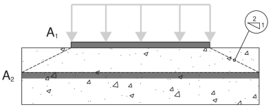
- A1 – Base plate loaded area
- A2 – Area of the concrete support with the same shape as A1
A1 é o loaded area of the base plate, enquanto A2 é o same loaded area projected at a 2H:1V slope into the concrete support. More details on these areas can be found in ACI 318-19 Seção 22.8.3.2.
Nisso base plate design with moment, the A1 area will be calculated using the full width of the base plate, \(B\) quanto pelo actual bearing length, \(Y\). The actual bearing length is measured from the edge of the base plate at the compression side towards the center of the plate.
\( A_1 = B \times Y \)
For most engineers, calculating A1 and A2 requires a lot of work, so they simply assume A1 = A2, que é conservador. No Software de placa de base Skyciv, iterações are performed to determine the actual A1 values and to maximize the capacity of the base plate.
The table below shows the iteration steps from SkyCiv to determine the bearing length Y, e subsequentemente, to determine the actual A1 and A2 areas.

Primeiro, an initial Y is assumed, and the A2 and A1 values are calculated based on the initial Y. These are then used to calculate the maximum bearing strength of the concrete, \(f_{p\_max}\), e o correspondente bearing force per unit length, \(q_{max}\). Once these are determined, the corresponding Y value is determined based on Eq. 4-32 of AISC DG1 3terceiro Edição. If the calculated Y does not match the initial Y, another iteration step is performed. A more detailed step-by-step calculation of the last iteration is shown in the next section.
Agora, taking the A2 and A1 values from the iteration, nós usamos Eq. 4-2 of AISC Design Guide 1, 3Edição RD, to determine \(f_{p\_max}\), the design bearing strength for concrete crushing:
\(f_{p\_max} = \phi \left( \min \left( 0.85 \, (f_c’) \sqrt{\dfrac{A_2}{A_1}}, \, 1.7 \, (f_c’) \right) \right)\)
\(f_{p\_max} = 0.65 \times \left( \min \left( 0.85 \times (3 \text{ ksi}) \times \sqrt{39.941}, \, 1.7 \times (3 \text{ ksi}) \right) \right) = 3.315 \text{ ksi}\)
Além disso, since this design is a Large Moment Case, the base plate has both a compression side and a tension side. Nesta situação, we should allow the concrete bearing to be at its full capacity and minimize the Y value. Então, any remaining tensile force, based on equilibrium of forces, will be taken by the anchors at the tension side.
Given this, we set \(f_{p\_actual}\) Caso de carga A \(f_{p\_max}\).
\(f_{p\_actual} = f_{p\_max} = 3.315 \text{ ksi}\)
Desde a 3.315 ksi ≤ 3.315 ksi, A capacidade de rolamento de concreto é suficiente.
Verificar #4: Calculate base plate yielding capacity at the bearing interface
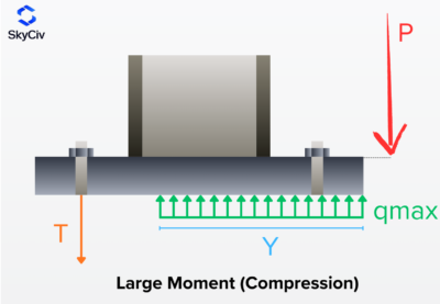
The next step is to determine if the base plate has enough capacity for the given load. As the moment load pushes the base plate against the concrete, the base plate has a tendency to yield due to flexure. We call this check the base plate yielding check on the bearing interface. There is also a separate yielding due to the tension load, and it will be covered in the next design check.
To check the base plate yielding, we need to determine the \(q_{max}\), which is the compression force per unit length. AISC DG1 3rd Ed. Eq. 4-37 dá \(q_{max}\)como:
\(q_{max} = f_{p\_max}B_{bp} = 3.315 \text{ ksi} \times 15 \text{ in} = 49.725 \text{ kip/in}\)
Então, we will calculate the Y-dimension. Although the Y-dimension is already calculated in the prior check, this section will show how we use the equations from AISC DG1. For this Large Moment Case, nós usamos Eq. 4-32 of AISC DG1, 3Edição RD.
For the plus case:
\(Y_{case1} = \left( f + \dfrac{L_{bp}}{2} \right) + \sqrt{\left( \left( f + \dfrac{L_{bp}}{2} \right)^2 \right) – \dfrac{2M_z}{q_{max}}}\)
\(Y_{case1} = \left( 5.5315 \text{ in} + \dfrac{15 \text{ in}}{2} \right) + \sqrt{\left( \left( 5.5315 \text{ in} + \dfrac{15 \text{ in}}{2} \right)^2 \right) – \dfrac{2 \times 5 \text{ kip·ft}}{49.725 \text{ kip/in}}}\)
\(Y_{case1} = 25.97 \text{ in}\)
For the minus case:
\(Y_{case2} = \left( f + \dfrac{L_{bp}}{2} \right) – \sqrt{\left( \left( f + \dfrac{L_{bp}}{2} \right)^2 \right) – \dfrac{2M_z}{q_{max}}}\)
\(Y_{case2} = \left( 5.5315 \text{ in} + \dfrac{15 \text{ in}}{2} \right) – \sqrt{\left( \left( 5.5315 \text{ in} + \dfrac{15 \text{ in}}{2} \right)^2 \right) – \dfrac{2 \times 5 \text{ kip·ft}}{49.725 \text{ kip/in}}}\)
\(Y_{case2} = 0.092925 \text{ in}\)
Note that this equation has + e – símbolos, so we get two values. Daqui, we need to determine which value makes more sense. Desde a 25.97 no is greater than the base plate length, 15 no, we will not consider this value. Então, nós vamos usar 0.092925 no Como o comprimento do rolamento.
\(Y = Y_{case2} = 0.092925 \text{ in}\)
A continuação, we calculate the cantilever lengths. Estes são os m and n dimensions from the figure below. Isso é baseado em AISC DG1 3rd Edition Section 4.3.1.
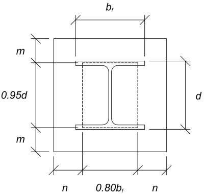
The calculated m and n cantilever values are:
\(m = \dfrac{L_{bp} – 0.95d_{col}}{2} = \dfrac{15 \text{ in} – 0.95 \times 8 \text{ in}}{2} = 3.7 \text{ in}\)
\(n = \dfrac{B_{bp} – 0.8b_f}{2} = \dfrac{15 \text{ in} – 0.8 \times 8 \text{ in}}{2} = 4.3 \text{ in}\)
Então, nós vamos compare the calculated Y value to the larger of m and n. Since Y is less than the larger cantilever length, nós vamos usar AISC DG1 3rd Ed. Eq. 4-52uma. This gives the required base plate thickness to be:
\(t_{p(req)} = \sqrt{\dfrac{4f_{p\_actual}Y \left( n – \dfrac{Y}{2} \right)}{\phi F_{y\_bp}}}\)
\(t_{p(req)} = \sqrt{\dfrac{4 \times 3.315 \text{ ksi} \times 0.092925 \text{ in} \times \left( 4.3 \text{ in} – \dfrac{0.092925 \text{ in}}{2} \right)}{0.9 \times 36 \text{ ksi}}} = 0.4022 \text{ in}\)
Finalmente, let’s compare it to the actual base plate thickness.
\(t_{p(actual)} = t_{bp} = 1 \text{ in}\)
Desde a 0.4022 no < 1 no, the yielding capacity of the base plate is suficiente.
Verificar #5: Calculate base plate yielding capacity at the tension interface
The required tensile force on the anchors at the tension side é igual to the resulting compression force on the compression side. This is because the base plate is only loaded with moment loads, and so the resulting couple forces are equal in magnitude.
To calculate the required strength of anchors, nós usamos AISC DG1 3rd Ed. Eq. 4-31.
\(T_u = q_{max}Y = 49.725 \text{ kip/in} \times 0.092925 \text{ in} = 4.6207 \text{ kip}\)
Então, nós calculamos o eccentricity of this tensile force from the column support. This is taken from the center of the anchor rod to the center of the column flange. Nós usamos Eq. 4-61 of the design guide to determine the eccentricity. In the equation, f is the distance of the anchor rod from the column centerline.
\(x = \left( f – \dfrac{d_{col}}{2} \right) + \dfrac{t_f}{2} = \left( 5.5315 \text{ in} – \dfrac{8 \text{ in}}{2} \right) + \dfrac{0.435 \text{ in}}{2} = 1.749 \text{ in}\)
Note that in this analysis, we take the whole base plate width as the section to resist the flexure, as we closely follow the AISC DG1 3rd Ed. guidelines. Other conservative bending widths could also be used.
Finalmente, we determine the required base plate thickness usando Eq. 4-62uma.
\(t_{p(req)} = \sqrt{\dfrac{4T_u x}{B_{bp}\phi F_{y\_bp}}} = \sqrt{\dfrac{4 \times 4.6207 \text{ kip} \times 1.749 \text{ in}}{15 \text{ in} \times 0.9 \times 36 \text{ ksi}}} = 0.25791 \text{ in}\)
Desde a 0.25791 no < 1 no, a yielding capacity of the base plate is suficiente.
Verificar #6: Verificações de âncora
The rest of the anchor design checks are not shown in this example. Please refer to other SkyCiv Base Plate Design Examples that covers capacity of ancoragem.
Resumo do projeto
O software de design da placa de base Skyciv pode gerar automaticamente um relatório de cálculo passo a passo para este exemplo de design. Ele também fornece um resumo dos cheques executados e suas proporções resultantes, facilitando o entendimento da informação. Abaixo está uma tabela de resumo de amostra, que está incluído no relatório.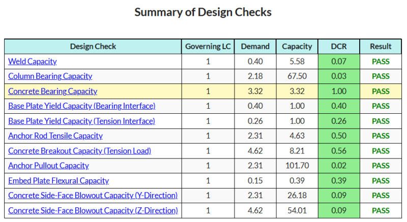
Compre software de placa de base
Compre a versão completa do módulo de design da placa de base por conta própria, sem outros módulos Skyciv. Isso oferece um conjunto completo de resultados para o design da placa de base, incluindo relatórios detalhados e mais funcionalidade.

