Introduction
In the following tutorial, we will explore how to apply snow loads in a Structure using Structural 3D. We will go step by step showing how to create nodes, members, sections, materials, supports, area loads, etc.
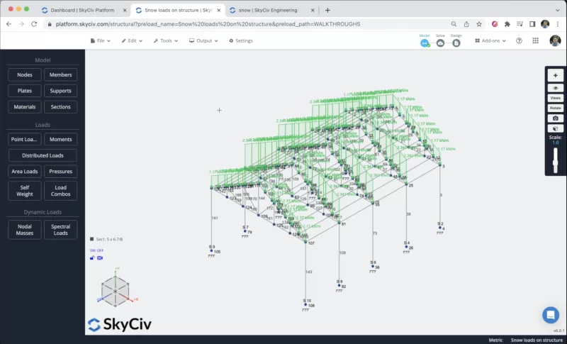
You have to open Structural 3D from your SkyCiv dashboard and create a new project, in this tutorial, we will be working on meters, so you can modify the units by going to settings > unit system and selecting metric
Member Creation
There are different ways to create members, using the form, and datasheet, but in this example, we will be using the pen tool for the member creation, you can activate the pen tool going to the right panel > pen > pen tool.
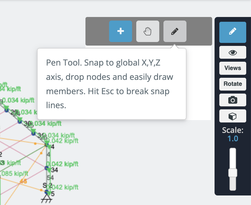
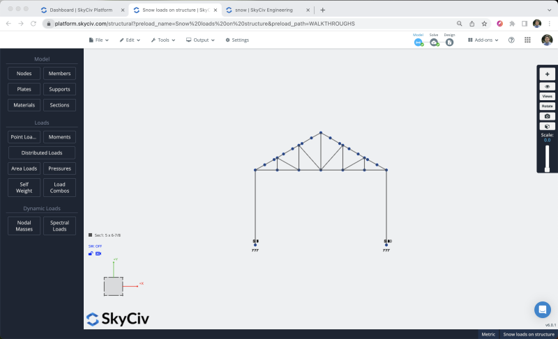
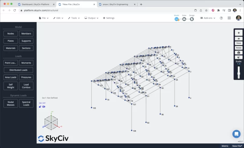
After we have the pen tool selected we can start to create all the frame members we will create a column member of 4m, and a beam of 7m, then create the roof with the biggest member of 2m as shown in the next image:
To avoid the creation of more nodes and members we will duplicate the frame that we created in the previous steps. To achieve this we need to select the whole frame by doing right click on the canvas > Select all or hit Ctrl + A on your keyboard. After we select the whole frame we can go to Edit > Operations > Repeat or hit Ctrl + D and we will repeat the members 4 times every 2.5m along the Z axis.
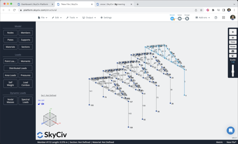
After this step, we will create the purlins for our structure.
Supports Assignment
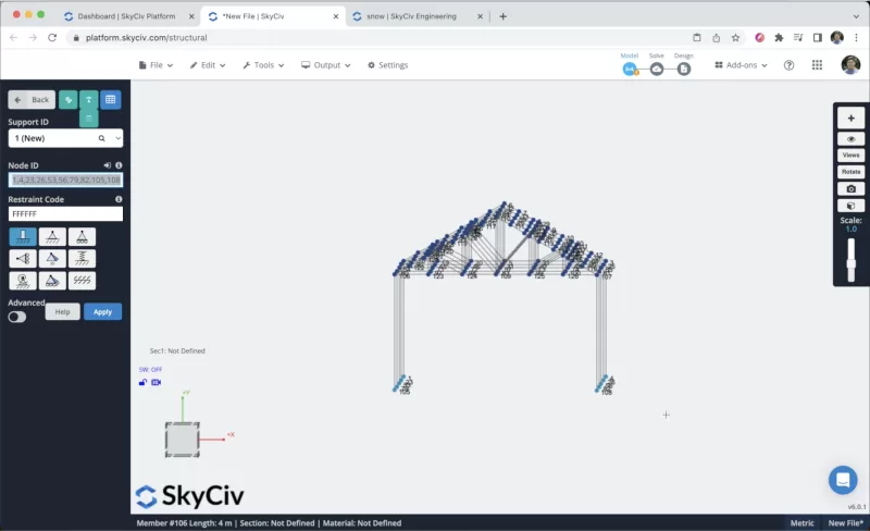
To add supports to our structure we have to select all the ground nodes, then go to Supports > Double Click on the Node ID field (If you have your nodes selected) > Select Fixed Support > Apply. After you create all your supports they should appear on your model.
Applying Snow Loads
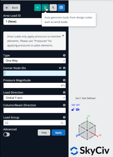
We will apply some area loads to our structure. To apply snow loads you can go to Area Loads and select the button that says: “Auto-generate loads from design codes such as wind loads”.
We can define our site data, we will select a risk category = II, and define the project Address in Minneapolis, and the program will calculate Wind and Snow Data for our structure.
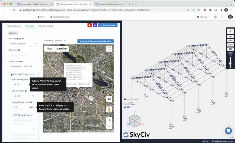
After we define the site data, we can click on Structure data to configure our project, in this example, we will select a building with a Gable Roof Profile with a roof pitch angle of 29.745.
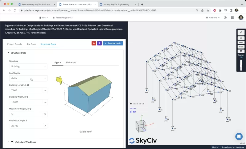
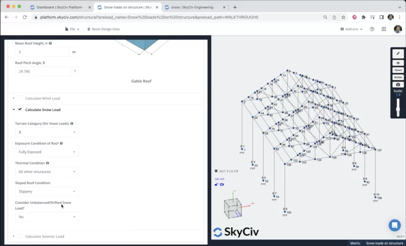
We need to define the terrain category, exposure condition of the roof, thermal condition, sloped roof condition, and if we will consider unbalanced/drifted snow loads. You can select the values shown in the following image:
Once, we have all the information, we can click on Generate Loads, the program will try to find the best way to apply Snow Loads in the structure, however, in cases like this where we have more complex geometries is harder task for the software and the result could be incorrect.
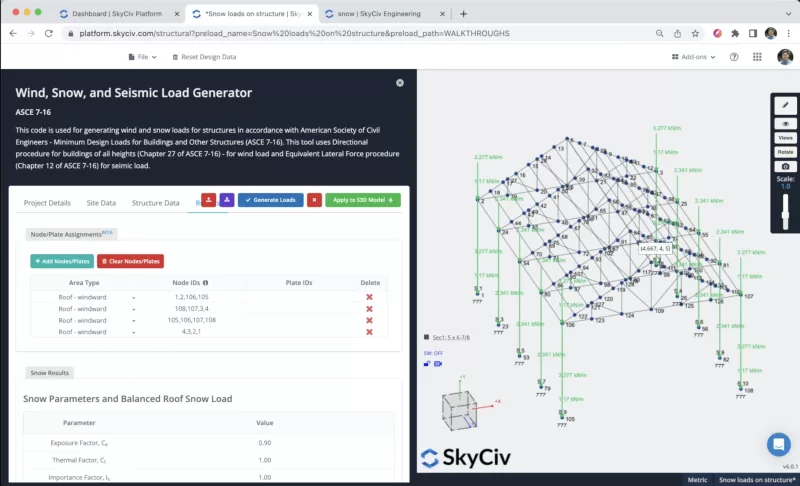
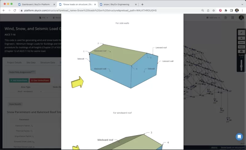
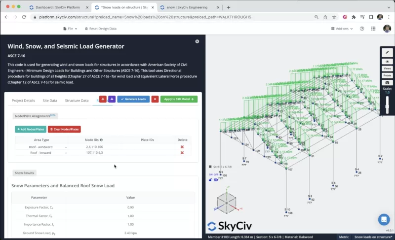
In order to apply the wind loads correctly we can erase all the auto-generated rows and begin to add our own area types. We can define which nodes will represent windward roofs, leewards roofs, etc. In the following image, you can see what would be the correct order to define these area types on the structure.
We need to define multiple area types in the structure, you can add the information as shown in the following image, and you can continuously check that the application of these area loads is correct on your structure members. The result should look like this:
Sections and materials
The next step will be the creation of sections and materials, in this example, we will be using the Section Builder module to create our sections, to access the Section Builder module we need to go to Sections > Builder. Once the section builder is opened, we can select sections from Shape Templates, in this case, we will select Database Shapes > Find: 5 x 6-7/8. We can modify the material to Oakwood on the right panel.
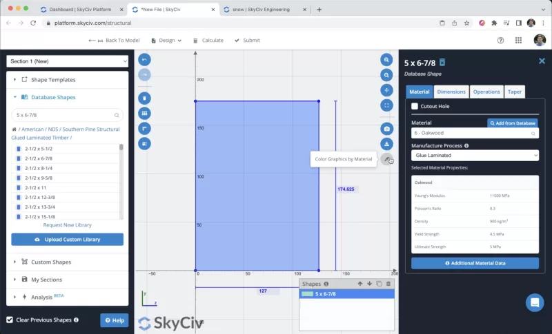
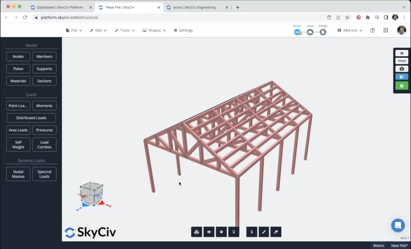
After we select our section we can click on Submit. By default, when we have members without sections defined, the new section will be assigned to them. If we open the 3D renderer we will see the following result.
Solving the model
After we finished the modeling of the structure, we can proceed to solve our Structure, we can do this by clicking on Solve > Linear Static, and it will take us to a new window where we will be able to see all the results of the members.
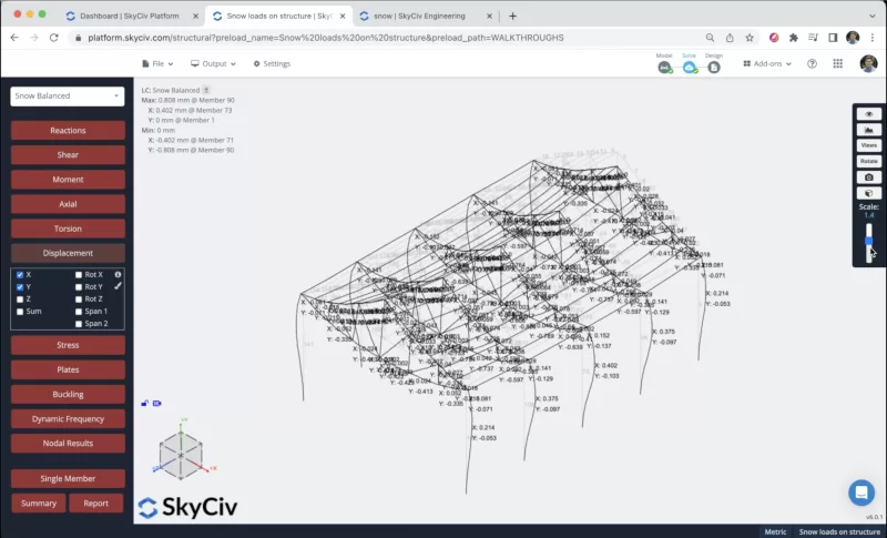
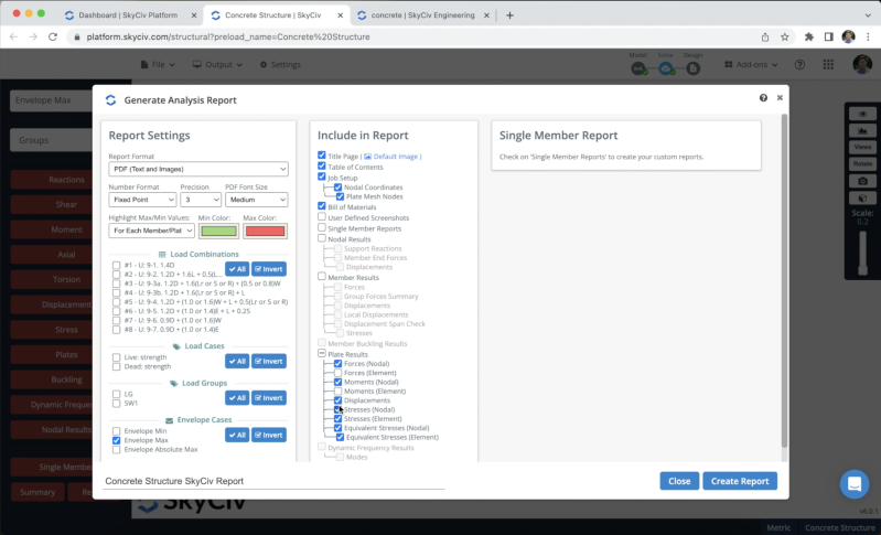
We can also create reports from the analysis, we can click on Report, customize the report as needed, specify what load combinations to include, etc. We can click on Create Report when we finish the configuration.
FAQ
It is recommended when you have complex geometries in your structures, when you have common geometries the program will try to generate these loads automatically in the correct way.
To create wind loads, you can refer to the following documentation: wind loads documentation
The process is very similar, you just need to follow the rules of nodes enumeration and select wall rectangles in the structure.


