What is a Moment Connection?
A Moment Connection in structural engineering is a joint that allows the transfer of bending moment forces between a column and beam (or any other two members). If a child member (a beam) has some internal moment, the connection should be able to transmit the load due to that moment.
The objective of moment connections is to simulate as close as possible a fixed joint, denoted by the fixity code FFFFFF - meaning the connection is rigid in all translation and rotational directions. This is also the reason why moment connections are called rigid connections.
While Shear Connections are dependent mostly on the web of a section, moment connections add to that by strengthening the connectivity of the flanges. This can be achieved through use of plate stiffeners, welds or other fixtures that strengthen and increase the rigidity of the connection between members.
Moment Connections are normally more rigid and as such is able to withstand a much higher moment load than shear connections. However, as more material are used to erect the connection, it is significantly more costly to use a moment connection as compared to a shear connection. Typically a structure would only have one or two unique moment connections to minimize the cost.
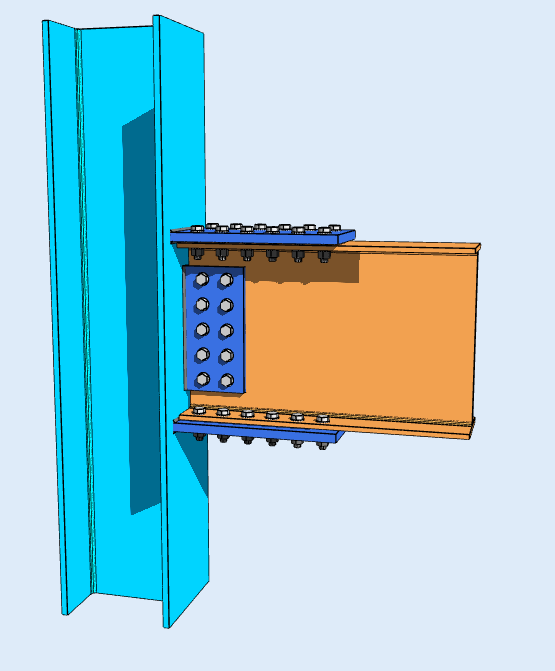
Flange Plate
A Flange Plate Connection connects the flange of the column to the web of the beam member. A plate is either bolted and/or welded to join the members to form a rigid fixture. An example of a flange plate connection can be seen from the adjacent image. This connection shows two plates bolted to the flanges of the beam member to connect it to the column. As the beam undergoes bending, it will be passed onto the connected member.
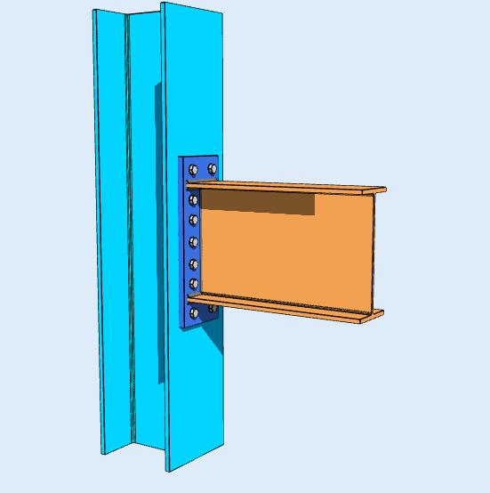
Extended End Plate
Extended end plates transfer moment between members using a rigid steel plate welded to the end of a beam that extends beyond one or both of the beam's flanges. This extension creates extra leverage, allowing additional rows of high-strength bolts to be placed outside the beam profile.
If the beam undergoes a heavy bending force, the extended plate provides a larger moment arm. This significantly increases the connection's stiffness and load capacity by efficiently resisting the tension and compression forces, making it ideal for high-stress seismic or heavy structural frames.
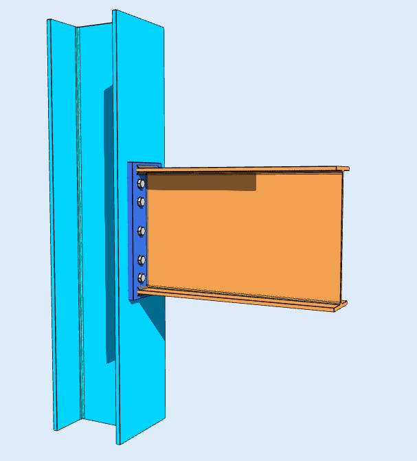
Flush End Plate
Flush end plates transfer moment between members using a rigid steel plate welded to the end of a beam, which is then bolted to the face of a column. Unlike extended end plates, a flush plate does not extend past the top or bottom flanges of the beam.
If the beam experiences a bending force, the tension and compression forces are transferred to the column primarily through the high-strength bolts located tightly between the beam's flanges, maintaining a clean, compact profile that aligns perfectly with the beam's outer edges.
Why Choose SkyCiv’s Moment Connection Calculator?
SkyCiv’s moment connection calculator streamlines the engineering process with precise, reliable results and an intuitive interface. By adhering to AISC 360-16 ASD and LRFD standards, the tool ensures code-compliant designs while saving time. Whether working on complex high-rise structures or industrial applications, the moment connection calculator is an indispensable tool for engineers seeking accurate and efficient solutions.
Related Tools
-
- Steel Connection Design Calculator
- SkyCiv Connection Design Software
- Bolted Splice Connection Calculator
- Vertical Bracing Connection Calculator
- Horizontal Bracing Connection Calculator
- Column Splice Connection Calculator
- Bolt Shear Strength Calculator
- Steel Design Capacity Software
- Weld Group Capacity Software
- Eccentrically Loaded Bolt Group Software