Scaffolding Load Capacity Calculator
The SkyCiv Quick Design Scaffolding Member Design Calculator allows engineers to design scaffolding to standards AISC 360-16, BS EN 12811-1:2003, and AS/NZS 1576. The scaffolding weight capacity calculator provides multiple design capacities for both scaffolding tubes and clamps. The design tool provides scaffolding utilization results that are calculated and detailed in a professional report allowing engineers to verify each result and understand the calculation steps behind them. Using the flag icon at the top left of the calculator , the following standards are available in our scaffolding design software:
- United States - AISC 360-16.
- Australian Standards - AS/NZS 1576 Scaffolding General Requirements.
- Europe/UK - BS EN 12811-1:2003 Temporary Works Equipment - Scaffolds.
The scaffolding load capacity calculator requires the geometry and material of the scaffolding member, the coupler data, the design loads (bending, shear, axial and torsion) as well as the effective length factors. The calculator can help engineers calculate scaffolding load capacity for results including axial compression, shear capacity and moment capacity. The calculator supports multiple types of couplers including right angle couplers, parallel couplers, swivel couplers and friction type sleeve couplers.
About Scaffolding Load Capacity Calculator
What is Tube and Clamp Scaffolding?
Tube and Clamp scaffolding is a common type of scaffolding system that consists of steel or aluminium tubes and clamps (also known as couplers or fittings) to connect the tubes together. Tube and coupler scaffolding is common in the construction industry where cheap and reliable temporary structures are required to facilitate efficient construction.
What is a Scaffolding Clamp?
In scaffolding a coupler refers to a fitting used to connect two scaffolding members. Couplers come in different types and options.
Right-angle clamps are used to connect horizontal and vertical scaffolding tubes and swivel clamps are used to connect bracing to the structure. End-to-end clamps such as sleeve couplers or joint pin couplers can be used to extend a straight run of scaffolding. A screw jack (also know as adjustable leg) can be used as a starting base for scaffolding with an adjustable height to ensure that level scaffolding can be achieved even on uneven surfaces.
Standard scaffolding tube has a 48.3 mm (1.900 inch) outer diameter (OD) and most clamps are designed for this standard sizing.
What couplers are available in the scaffolding load capacity calculator?
In the scaffolding weight capacity calculator the connections included depend upon the design standard referenced and what is included in the provisions of that design standard.
The BS EN 12811-1:2003 Annex C gives characteristic values of the resistances for the following couplers:
- Right-Angle Coupler
- Friction Type Sleeve Coupler
- Swivel Coupler
- Parallel Coupler
These couplers are divided into class A and class B couplers with the characteristic strength given for each with respect to the types of load it can carry. A partial safety factor of 1.5 is then used to account for load action variability and a partial safety factor of 1.1 is used for resistance variability. For example, a Class A right-angle coupler has a characteristic slipping resistance of 10.0 kN. We can then determine a working load limit of 10 / (1.1 * 1.5) = 6.1 kN for Class A right-angle couplers resisting a slipping force.
The AS/NZS 1576.2 (Couplers and accessories) gives guidance on the minimum testing criteria for the following couplers:
- Right-Angle Coupler
- Swivel Coupler
- End-to-End couplers (i.e. Friction Type Sleeve couplers)
- Parallel Coupler
- Putlog Coupler
- Putlog Blade
- Check Coupler
- Adjustable Leg / Adjustable Baseplate / Adjustable Swivel Baseplate
- Flange Clamp
- Plain Pintle Castor
- Adjustable Castor
In order to get the working load limit (WLL) the minimum testing forces required to pass the standard should be reduced by a factor of safety. The AS/NZS 1576.2 does not explicitly specify the safety of factor except for Adjustable Legs / Baseplates in which a factor of safety of 2.5 is used and for Right-Angle couplers and Swivel couplers for slip resistance in which a factor of safety of 2 is used. We have considered a factor of safety of 2.0 for all couplers except bases which generally gives similar working load limits to the BS EN 12811-1:2003. For example a right-angle coupler has a slipping test force of 12.5 kN. We can then determine a minimum working load limit of 12.5/2 = 6.25 kN for right-angle couplers resisting a slipping force.
Where a manufacturer tests beyond the requirements of the standard they can achieve a higher working load limit for their product. For simplicity we have simply referred to the minimum requirements of the standard. When using the SkyCiv Scaffolding Design Software using the custom connection can allow a user to specify specific working load limits provided by a manufacturer for a connection.
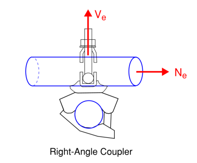
Right angle coupler
Right-angle couplers connect scaffolding tubes at exactly a 90-degree angle (hence the name) creating stable joints. Right-angle couplers are commonly used to connect vertical and horizontal scaffolding members.
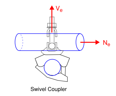
Swivel coupler
The swivel coupler is similar to the right-angle coupler however allows swivelling rather than having a fixed 90 degree joint. This allows the scaffolding tubes to rotate independently when required and can be used for connecting bracing elements or non-rectangular arrangements within the scaffold structure.
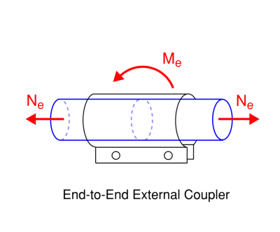
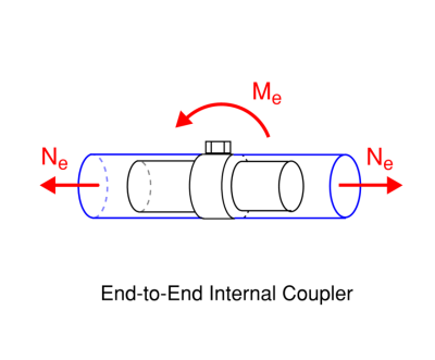
End to End Couplers
End to end couplers join two scaffolding members together in a straight line. These can be placed externally to the scaffolding tube (friction type sleeve couplers, external sleeve couplers) or internally in the scaffolding tube (expanding joint pin couplers). These connections allow the transfer of moments between members and the transfer of compression forces however do not provide resistance in tension. Where tension transfer is required a spliced arrangement should be used instead.
Expanding Joint pin couplers work by fitting inside scaffolding and then expanding flush against the inside of the scaffolding tube.
Sleeve couplers sit outside the scaffolding tubes and are tightened to be flush against the outside of the scaffolding tube.
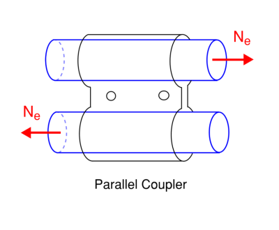
Parallel coupler
The parallel coupler is used to create a splice connection or lap connection between scaffolding tubes by connecting them in parallel. This type of connection can be used to transfer axial forces between scaffolding members.
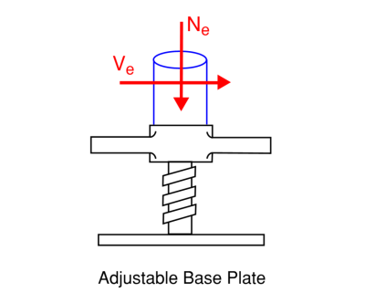
Screw Jack
A screw jack has a thread that allows for an adjustable base for supporting vertical scaffolding members at the base of the scaffolding structure. By adjusting the screw jack, level scaffolding can be erected by the construction team even on uneven surfaces. The screw jack then supports the scaffolding structure by transferring compression and shear forces into the foundation.
Scaffolding Load Capacity
Standard scaffolding tube has a 48.3 mm (1.900 inch) outer diameter. Since there are only a few section thicknesses and steel grades that are manufactured there are only a few different possible scaffolding load capacities. Since it is difficult to visually identify the section thickness and grade of a scaff tube on site it is generally advised to be conservative and use the thinnest and lowest grade section that would be available on site in design calculations.
When scaffolding tube is resisting tension forces only we can calculate the scaffolding load capacity by the following formula:
Nt = At * fy * φ
where:
- At is the area of the scaffold tube
- fy is the yield strength of the scaffold tube
- φ is a strength reduction safety factor
Scaffolding Load Capacity Example
For a 250 MPa yield strength 48.3x3.2 mm CHS the capacity according to the Australian standard is:
Nt = At * fy * φ
Nt = 453.4 mm2 * 250 MPa * 0.9 = 102.01 kN
Scaffolding Load Capacity Tables
Other tension strengths can be taken from the scaffolding load capacity table below. The values have been adopted based on the scaffolding load capacity formula for the relevant design standards.
| Design Standard | Section | Design Tension Strength |
|---|---|---|
| AU | 48.3x3.2 (Grade 250) | 102.01 |
| EU | 48.3x3.2 (Grade 250) | 96.86 |
| US | 1.900x0.120 (Grade A53) | 88.2 (19.82 kip) |
The scaffolding load capacity formula for a compression member is different since the member can buckle due to the compressive forces. We can calculate the scaffolding weight capacity for different effective lengths for compression scaffolding members using the quick design calculator and a batch run.
| Design Standard | Section | Le (m) | |||||
| 0 | 1 | 2 | 3 | 4 | 5 | ||
| AU | 48.3x3.2 (Grade 250) | 102.01 kN | 86.67 kN | 44.2 kN | 21.26 kN | 12.24 kN | 7.93 kN |
| EU | 48.3x3.2 (Grade 250) | 96.86 kN | 72.23 kN | 36.38 kN | 19.04 kN | 11.44 kN | 7.6 kN |
We can also construct a table for typical scaffolding size used in the US for different spans to get more scaffolding load capacity examples.
| Standard | Size | Le (ft) | ||||
| 3 | 6 | 9 | 12 | 15 | ||
| US | 1.900x0.120 (A53) | 16.8 kip | 10.23 kip | 4.89 kip | 2.75 kip | 1.76 kip |
What effective length parameters are used in the scaffolding load capacity calculator?
Round HSS sections or CHS sections are not susceptible to lateral-torsional buckling (buckling under bending) however they can buckle due to compressive forces. The SkyCiv Scaffolding Design Software takes a input for the effective length factor which is used in buckling calculations. Where the SkyCiv S3D integration for scaffolding software is used the effective length factors can be automatically generated based on the member restraints in the model.
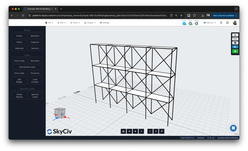
An integrated version of the calculator for SkyCiv S3D is available to import all eligible members into the scaffolding design module and run all scaffolding load capacity checks at once. The integration can automatically determine appropriate effective length factors based on the member restraints in the model. You can find out more about using the integration in our Scaffolding Design Tutorial in SkyCiv S3D.
What loads should be considered for scaffolding?
Engineers working on scaffolding systems should design them to resist various types of loads, these loads include:
- Dead Loads generally from the weight of the scaffolding system itself.
- Live Loads generally from workers and equipment used on the scaffolding.
- Wind Loads depend on local conditions and standards.
- Snow Loads where applicable and depending on local conditions and standards.
- Seismic Loads in areas prone to earthquakes and depending on local conditions and standards.
Once the loads have been determined by a qualified structural engineer they can be applied in the design load section of the calculator in the form of bending, shear, and axial force.
How does a scaffold Screw Jack Work?
A screw jack can resist compression and shear forces transferred through scaffolding and can then transfer the forces to the ground. A base plate is used to spread compression forces over a greater bearing area and a sole board is commonly placed under the base to gain additional bearing area and therefore increase bearing capacity. Bases often have holes for anchors that can be installed in a concrete blinding or foundation to help resist shear forces and prevent sliding of the scaffolding base.
The European Scaffolding Standard has a provision for the design of screw jacks located in Annex B.
The Australian Standard AS 1576.2 Section 4.3 discusses the minimum working load limit for steel and aluminium adjustable screw jacks.
Frequently asked questions
What unit system is supported?
Both metric and imperial unit systems are available. To change unit systems click the cog at the top left of the input panel.
What material properties are considered?
The scaffolding design tools allow users to enter the following material properties:
- Modulus Of Elasticity
- Modulus Of Rigidity
- Slenderness Compression Limit
- Yield Strength of Member
- Ultimate Strength of Member
What design codes are supported?
The scaffolding design software supports the design of scaffolding to the following standards:
- AISC 360-16 Scaffolding Design Software.
- AS/NZS 1576 Scaffolding Design Software.
- BS EN 12811-1:2003 Scaffolding Design Software.
These options can be accessed via the flag icon at the top of the left side input panel to change the design standard.
What analysis is used to calculate the resistance of couplers?
The scaffolding design module consists of the evaluation of coupler capacities based on the linear static analysis of the members. For the European version of the design check coupler capacities as given in Annex C of EN 12811.1 are used in combination with the required partial factors of safety. For the Australian version coupler testing requirements are given in AS 1576.2 and these values are used to determine the minimum working load limit of the fitting.
Is scaffolding with base jacks supported?
The European and Australian version of the tool supports scaffolding with base jacks. The US version of the tool does not currently support the design of scaffolding with base jacks.
Related Tools
About SkyCiv
SkyCiv offers a wide range of Cloud Structural Analysis and Design Software for engineers. As a constantly evolving tech company, we're committed to innovating and challenging existing workflows to save engineers time in their work processes and designs.
