Introduction
In the following tutorial, we will explore how to model, analyse and design a concrete slab on grade using the SkyCiv software.
This tutorial includes a step-by-step guide on:
- Creating plates,
- Creating holes in plates,
- Assigning loads and load combinations to the model,
- Applying materials and thickness to plate,
- Reviewing plate local axis
- Meshing plates,
- Assign supports to plates,
- Solving and reviewing model results
- Using the Plate Design Module.
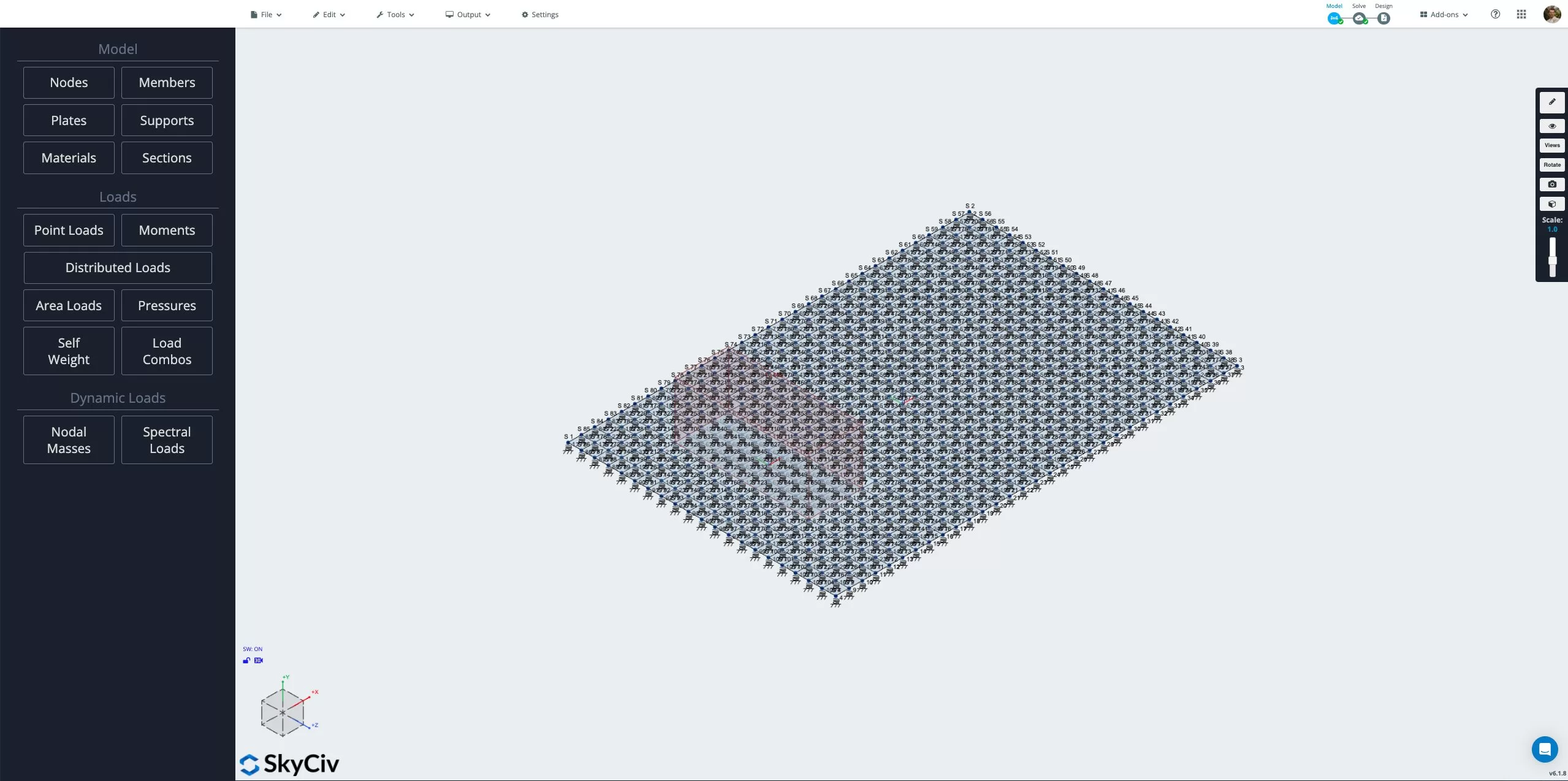
To begin creating the model, open Structural 3D from the SkyCiv dashboard and create a new project. In this tutorial, we will be working in metres. You can modify the units for your model by going to settings > unit system and selecting metric.
Creating Plates for Slabs
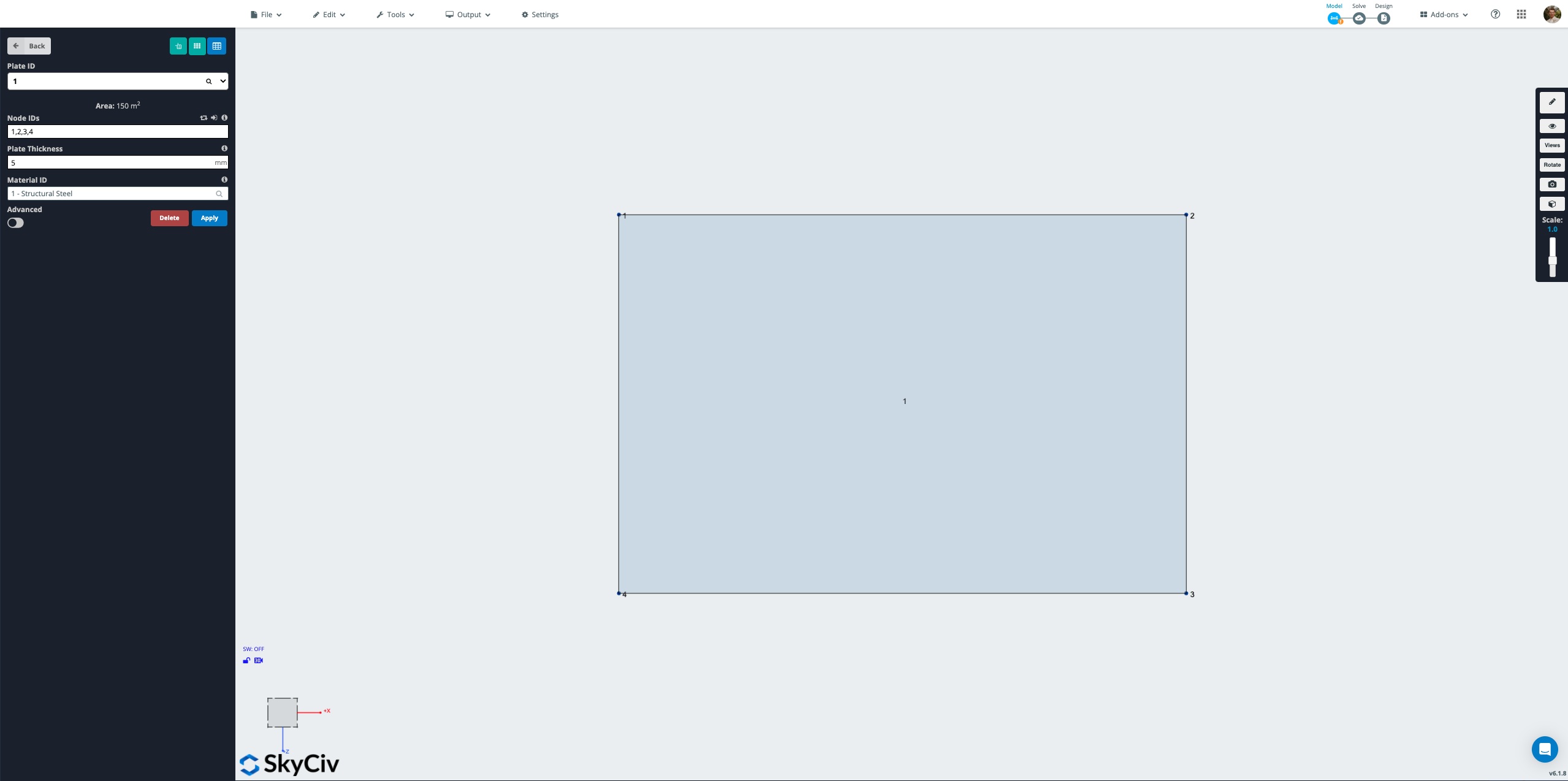
The slab for the model will be created using plate elements. Firstly we define the nodes for the outline of the slab. To create the nodes go to the Nodes menu. From this menu, we can input the X, Y and Z coordinates for each node individually, clicking Apply for each node to add them into the model.
Nodes will be applied at the following coordinates (X, Y, Z):
- 0, 0, 0
- 15, 0, 0
- 15, 0, 10
- 0, 0, 10
You can also define nodes by going to Nodes > Open Datasheet and inputting nodes directly in table form. This is useful for complex slabs with a large number of nodes.

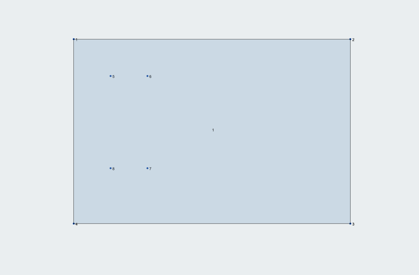
In this tutorial, a pressure load will be applied to the slab in a specific area 2 x 5 metre area and therefore we need to define a second plate across the designated area the pressure will be applied. To ensure we do not double up on plates across this designated area, we first need to create a hole in our main plate. We start by defining the nodes to outline the area for the hole. Go to the Nodes menu and create four nodes at the following coordinates (X, Y, Z), clicking Apply to create each node:
- 2, 0, 2
- 4, 0, 2
- 4, 0, 7
- 2, 0, 7
With the nodes created to outline the hole, open the hole menu by right clicking on the plate and selecting Plate Hole. You can also access the Plate Hole tool by selecting the main plate which will bring up the plate menu and selecting the Plate Hole button at the top of the Plate menu.
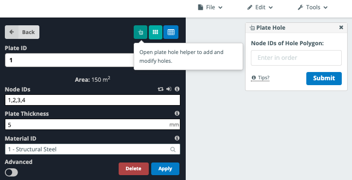
With the Plate Hole menu open, we can input the nodes we defined earlier for the outline of the hole. There are a few things to keep in mind when creating holes in plates:
- Node IDs for holes must be entered in order.
- A hole must not touch the border of the plate and must be fully within the plate area.
- Holes must not overlap or exist within other holes.
Enter nodes 5, 6, 7 and 8 and select Submit to add the hole to the plate.
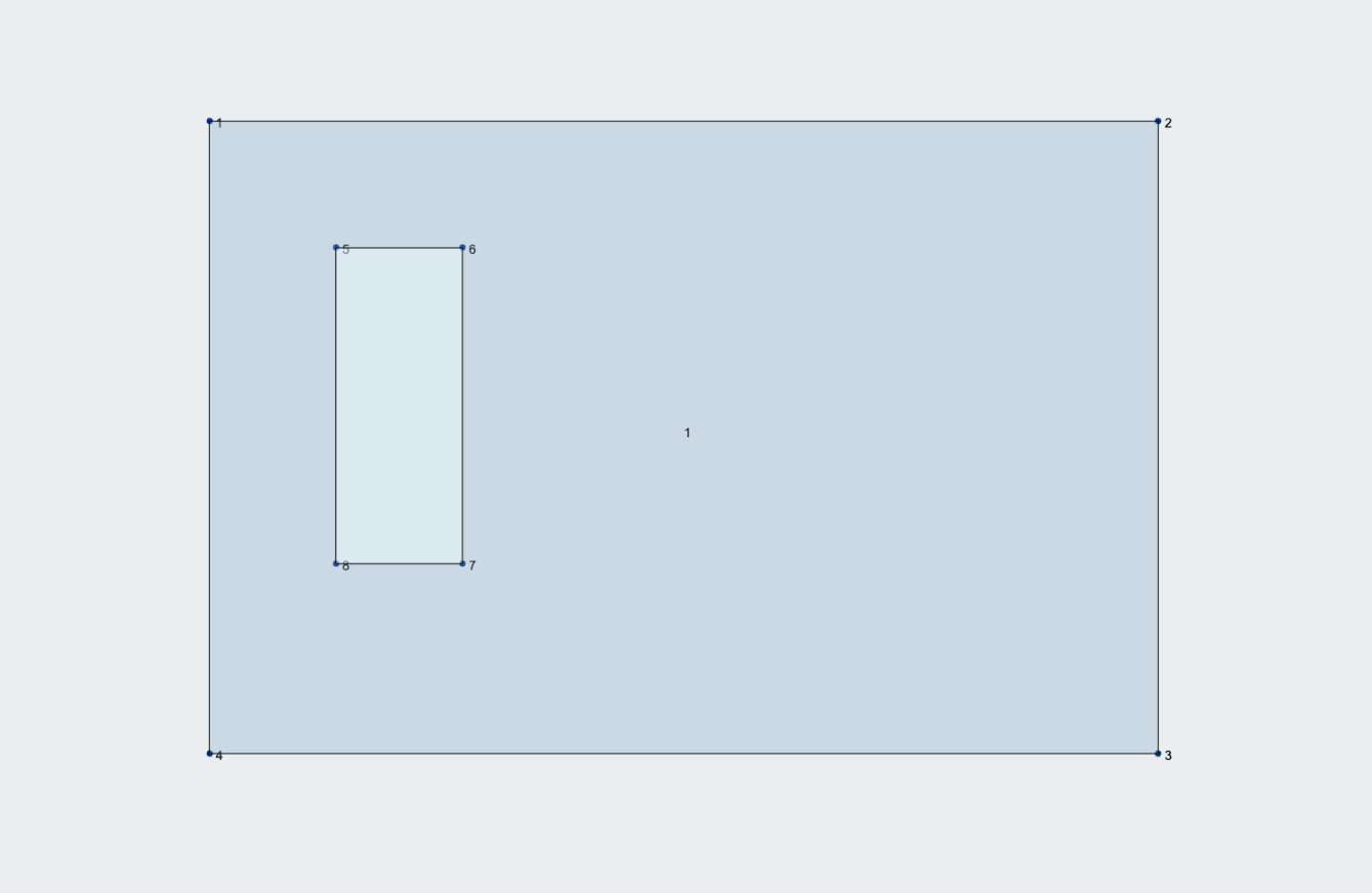
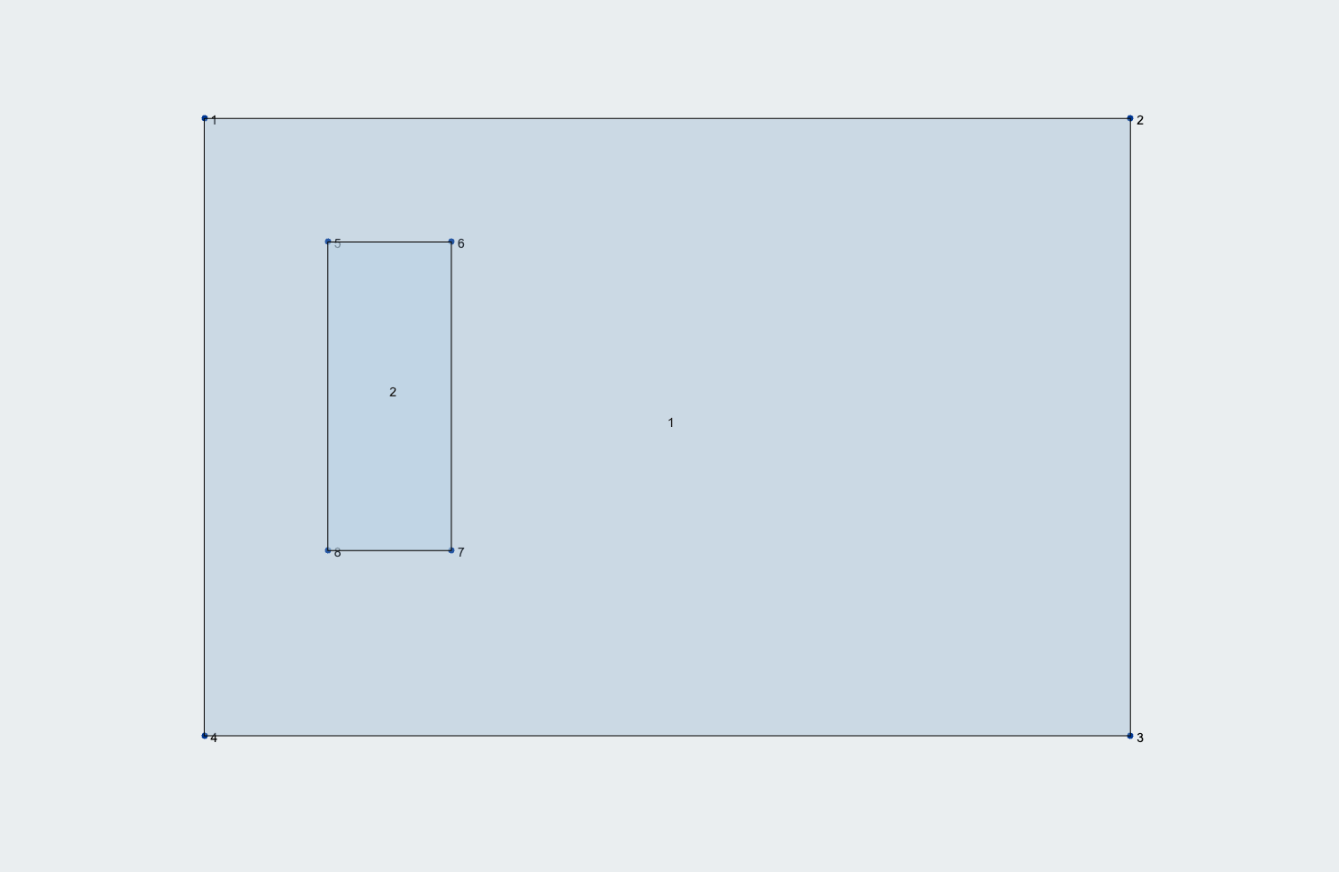
With the hole created, we can now add a second plate to fill the hole so that can apply a pressure to the plate. Go to the Plates menu and click around each of the corner nodes of the hole to draw an outline for the second plate.
Assigning Loads and Load Combinations
Next, we will assign loads to our model. We will start by assigning a live pressure load to the 2nd plate we defined across the hole earlier. Go to the Pressure menu and input the plate you wish to apply the pressure to (Plate 2) in the Plate ID input box. Enter a pressure of -10 kPa in the Y Magnitude input box. In this example, we will also rename the load to “Q” in the Load Group input box to denote a live load.
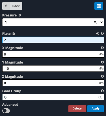
Click Apply to apply the pressure to the model.
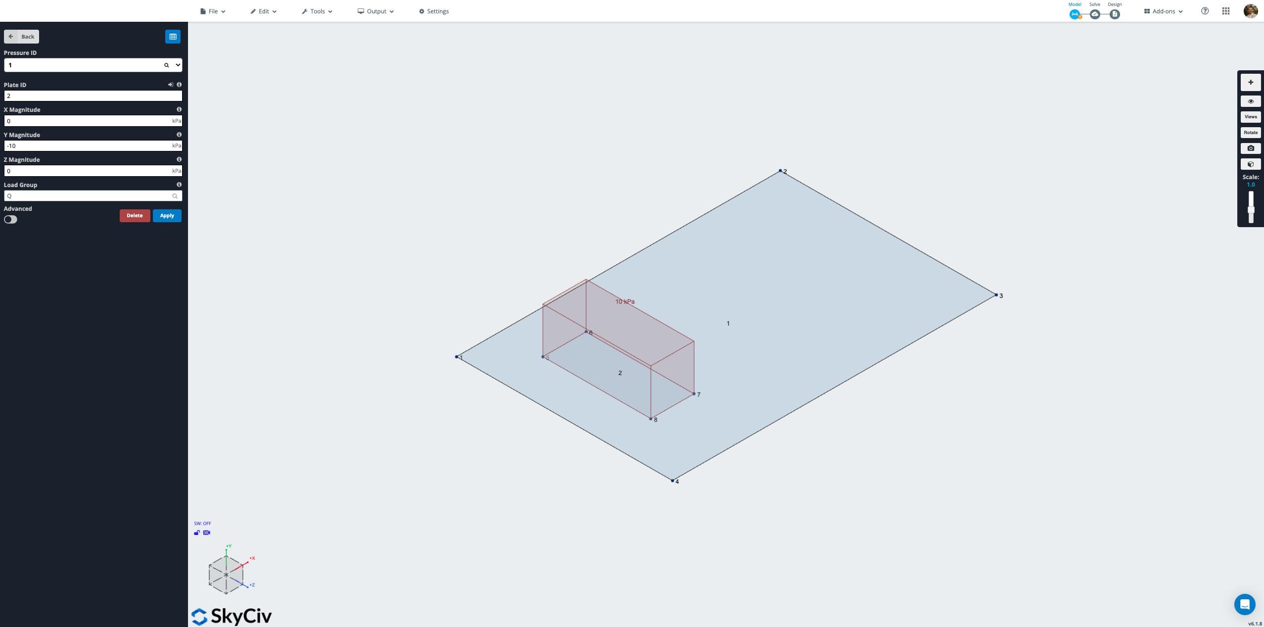
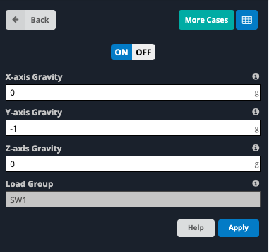
We will also assign a gravity load to the model to account for the self-weight of the slab. Go to the Self Weight menu and select On to enable self-weight in the model. By default, this will apply a -1 g (9.81 m/s2) self-weight in the y-direction across the entire model.
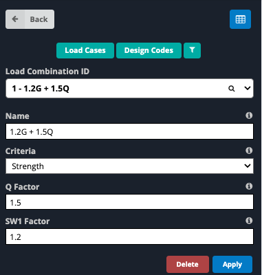
With loads applied to the model, the next step is to define load combinations. Go to the Load Combos menu. In this example we will define two load combinations, one for strength and one for serviceability. For the strength case, enter the following data into the input boxes:
- Name: 1.2G + 1.5Q
- Criteria: Strength
- Q Factor: 1.5
- SW1 Factor: 1.2
Click Apply to add the load combination. For the serviceability case, input the following data into the input boxes and select Apply:
- Name: G + Q
- Criteria: Serviceability
- Q Factor: 1
- SW1 Factor: 1
Alternatively, load combinations can be defined directly based on a specific code. Clicking on Load Combos > Design Codes brings up a window containing design codes from a database that generate load combinations relevant to that specific design code.
Apply Material and Thickness to Plate
We need to assign a material to each plate. SkyCiv is preloaded with a selection of standard materials by default. SkyCiv also has a database for a variety of materials that can be loaded into the model. For this example we will use a 32MPa concrete that complies with the Australian concrete code AS3600. This material needs to be added from the database. Click Materials > Database to bring up the materials database. Then select the following from the four drop down boxes:
- Metric
- Concrete
- Australian AS3600-2009
- AS-CONC2009-32
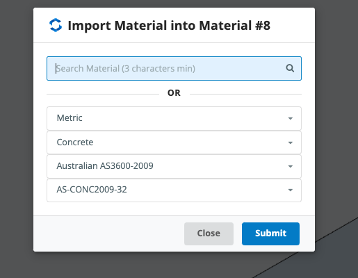
Properties of the material will appear for review. Select Submit to load the material into the model.
With the material defined, we can now assign the material and plate thickness to the plates in the model. Go to the Plates menu. In the modelling window, hold down the Ctrl button (⌘ on Mac) whilst clicking and dragging across the plates until both plates are selected. The Multi-Edit Plates menu will open on the left-hand side window. Change the input boxes to the following values:
- Plate Thickness: 200mm
- Material ID: 8 – Australian AS3600-2009 – AS-CONC2009-50
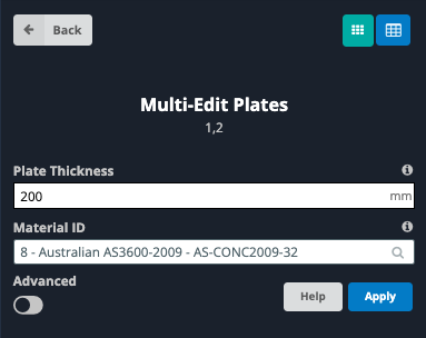
Click Apply to apply the material and thickness to each plate. If a “Multi-Edit Confirmation” message pops up, confirm the plates being edited are correct and select Yes.
Review Plate Local Axis
We are nearly ready to mesh the plates but first we need to check that the plate’s local axis are correctly aligned. To view the local axis of the plate click on the Eye Symbol on the right-hand side of the screen to bring up the Visibility Settings and check the Local Axis checkbox.
We want to ensure each plate’s local X, Y and Z axis are aligned in the same direction. We also want to ensure the local Z axis is orientated to be pointing upwards. This is to allow the program to correctly assign the top of the slab when checking results and completing the slab design in the Plate Design module.
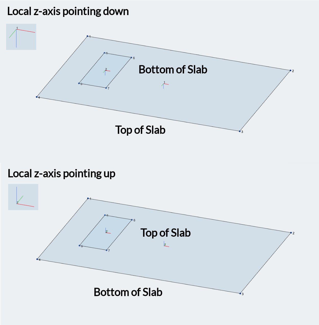
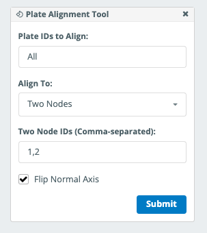
If one of the plates local axis are misaligned, we can re-align it by going to the Edit menu at the top of the screen and going to Plates > Plate Alignment Tool. Enter the plate to be realigned in the Plate ID’s to Align input box. There are a few options for what the plate will be realigned to from the Align To input box. A brief summary of how each type functions is below:
- Another Plate: Realigns specified plates to match the local axis of another plate.
- Vector: Uses vector coordinates (X, Y, Z) with reference to the global axis to align the local x-axis of the plate. For example, entering 0, 0, 1 will align the specified plate’s local axis with the global z-axis.
- Two Nodes: Aligns the specified plate’s local x-axis to be parallel with the line drawn between the two specified nodes (must be in the same plane as the plate).
- Member: Aligns the specified plate’s local x-axis to be parallel with the specified member (must be in the same plane as the plate).
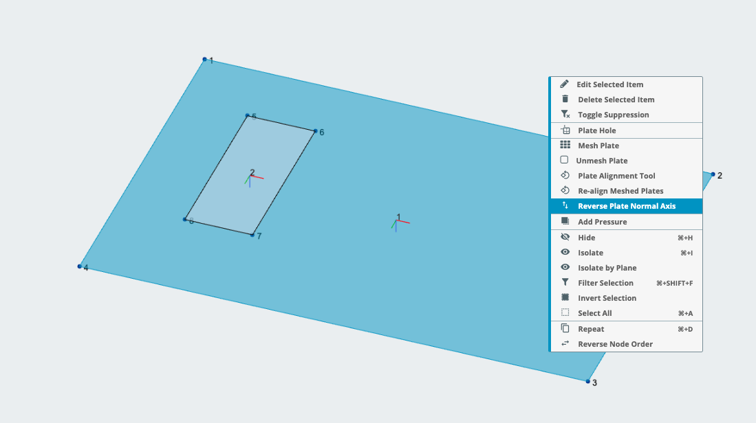
The local Z-axis can be flipped by selecting Flip Normal Axis check box when using the plate alignment tool with the Vector, Two Nodes or Member alignment options. Alternatively, the local z-axis can be flipped by right clicking the specific plate and selecting Reverse Plate Normal Axis.
Meshing The Plates
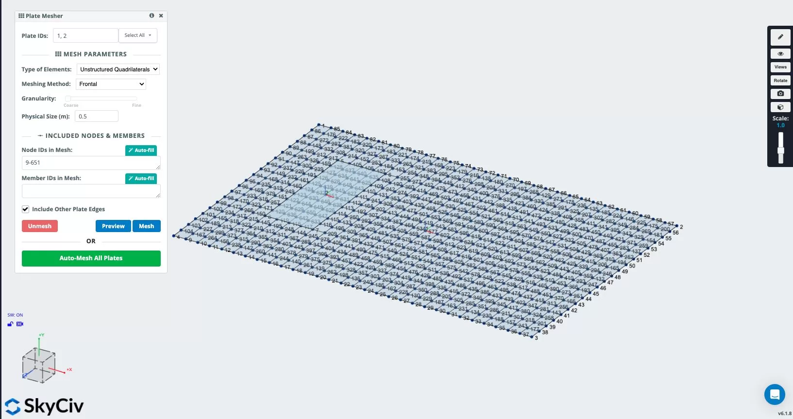
With the local axis of the plates correctly aligned, the next step is to mesh the plates. Open the plate mesher by going to the Edit menu at the top of the screen and going to Plates > Plate Mesher. In the Plate IDs input box, select All Plates from the dropdown arrow.
As this model features a hole in the plate, we must use Unstructured Quadrilaterals to generate the mesh. Select Unstructured Quadrilaterals from the Type Elements input box to. In the Physical Size (m) input box, enter 0.5 to adopt a 0.5m mesh across the plates. Select Preview to review the mesh on the model and then select Commit.
Assigning Supports
With the plates successfully meshed, the next step is to assign supports to the model. As this is a slab on grade, the slab is continuously supported on soil which will have varied levels of stiffness depending on the specific site. To capture this behaviour we want to model supports across the plate area with springs.
S3D contains a specific tool to allow models to be assigned with multiple spring supports at once. Go to Supports > Add a Surface Spring Support. This will bring up the Surface Spring Support menu.
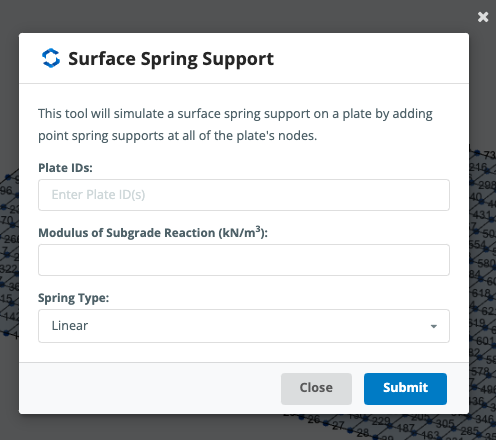
Enter the plate ID’s for the supports to be assigned to (1, 2) in the Plate IDs input box. The Modulus of Subgrade Reaction (kN/m3) is a measure of the soil’s stiffness. This value needs to be assigned by a geotechnical engineer or through engineering judgement. The value is used by S3D to calculate the relevant spring stiffness value to assign and is calculated by dividing the input value by the applicable mesh area. For our example, we will assign a modulus of subgrade reaction of 25000 kN/m3.
Some typical values for Subgrade Reaction Modulus can be found in the below table:
| Soil Type | kN/m³ | lb/in³ |
|---|---|---|
| Dry or Moist Sand | ||
| Loose | 8,000 – 25,000 | 30 – 90 |
| Medium | 25,000 – 125,000 | 90 – 450 |
| Dense | 125,000 – 375,000 | 450 – 1,350 |
| Saturated Sand | ||
| Loose | 10,000 – 15,000 | 35 – 55 |
| Medium | 35,000 – 40,000 | 125 – 145 |
| Dense | 130,000 – 150,000 | 475 – 550 |
| Clay | ||
| Stiff | 10,000 – 25,000 | 40 – 90 |
| Very Stiff | 25,000 – 50,000 | 90 – 185 |
| Hard | 50,000+ | 185+ |
Finally, we want to assign the Spring Type to be Compression Only. This ensures our spring supports will not provide restraint to the slab in the event that the slab was to lift upward away from the soil when subjected to loading. Click Submit to apply the supports to the model.
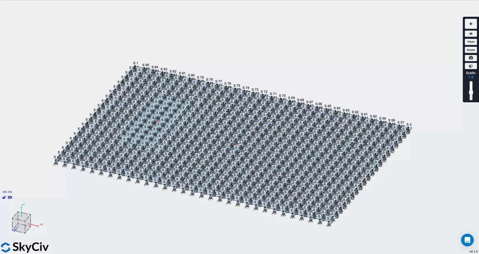
We also need to assign lateral restraints to the model. Lateral restraints can be assigned with spring supports by selecting the support you wish to update and updating the fixity code for the relevant direction to “F” to represent a fixed value or “S” to represent a spring with user defined stiffness value.
In our example the lateral restraints are only used to provide model stability and we are not concerned about lateral behaviour. Holding Ctrl (⌘ on Mac), select supports 1 and 4 located at the corners of the left side of the slab. The Multi-Edit Supports menu will open on the left-hand side of the screen and the Restraint Code input box should currently be listed as RSRRRR. Update the Restraint Code to be FSFRRR. This will apply a fixity to the translational restraints in the global X and Z directions. Click Apply to update the restraints in the model.
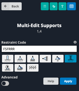
Please note, if you were interested in analysing the slab performance under lateral load, you may choose to apply a spring (“S” fixity code) to reflect the soils horizontal modulus of subgrade reaction and/or friction between the slab and the soil. These values would also need to be determined through consultation with a geotechnical engineer or using engineering judgement.
Solving The Model And Viewing Results
The model is now ready to be solved. We will use linear-static analysis to solve our model. At the top right of the screen next to the Model button, hover over the Solve button and click Linear Static (Default) to run the analysis.
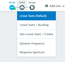
Once the solver has run, we will be able to see the results of our analysis. As this model is built using plates, we will use the Plates result button from the results menu. After clicking plates, we can choose from a variety of results to display by selecting the result the from the drop down menu. Results that can be viewed include
- Membrane Forces
- Displacement
- Moments
- Shear Forces
- Stresses
- Soil Pressures
- Wood-Armour Results
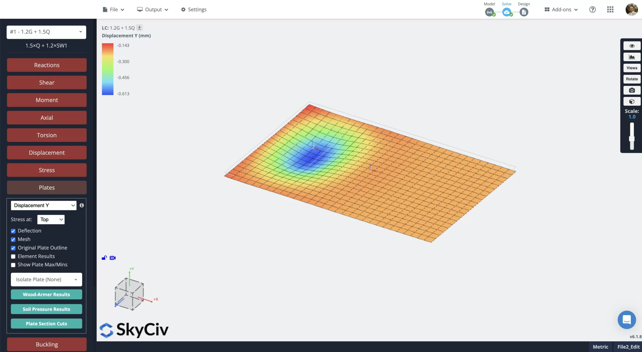
Design Using The Plate Design Module
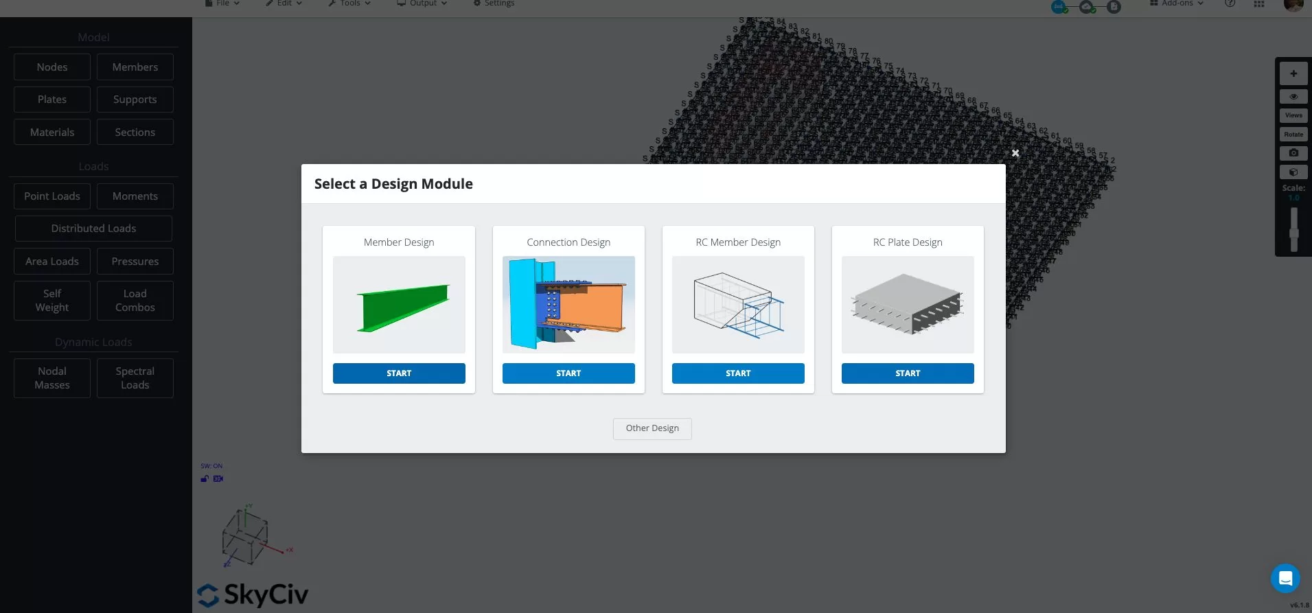
Once we have run our model and have verified that the model is behaving as expected, we can then complete the design of our slab through the Plate Design module. To open the Plate Design Module module, hover over the Design button next to the solve button at the top of the screen and select Start New Code. From the window that pops up, click START under RC Plate Design and select the design code you would like to use for the module from the dropdown menu and click START. For this example, we will be using AS 3600:2018.
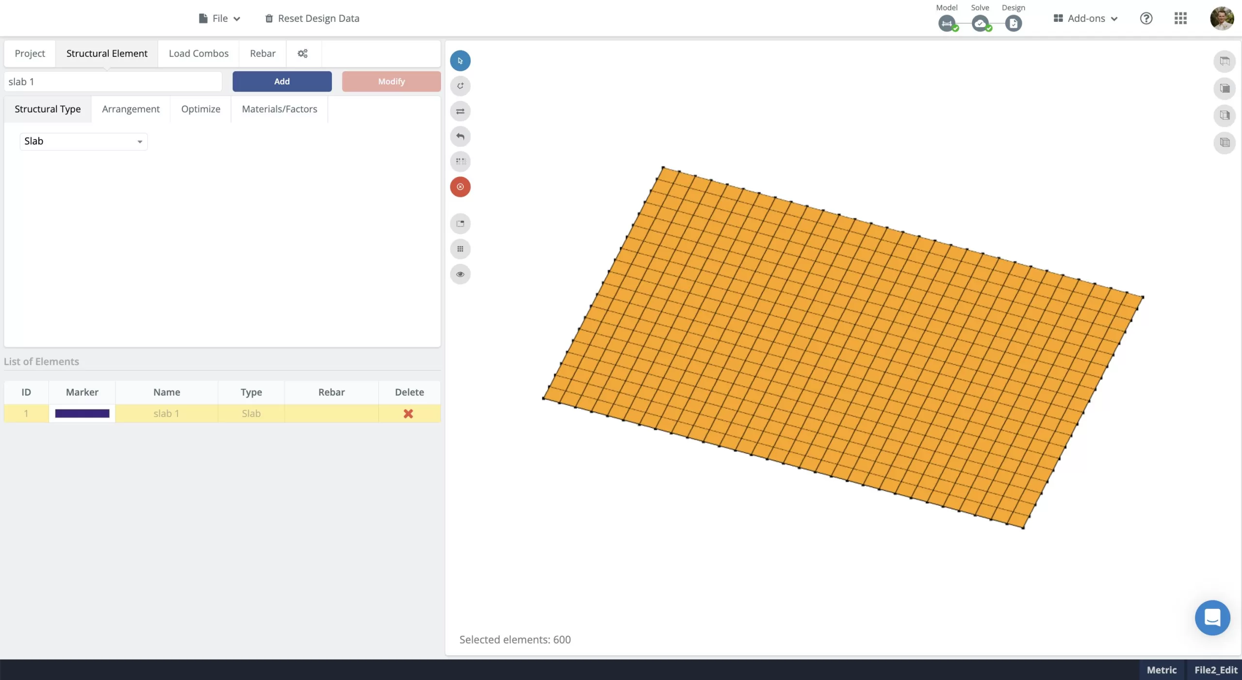
With the Plate Design module open, we need to define our structural elements and assign properties to the elements. Navigate to the Structural Elements tab which will open up in the Structural Type tab by default. The areas that can be selected are based upon the mesh we defined in our model previously. This allows us to choose areas where we may want to provide specific reinforcement or different concrete strengths. For this example we will apply our reinforcement uniformly across the entire slab. To select the entire slab, hold the Ctrl key (⌘ on Mac) and drag the mouse across the entire slab area. If done correctly, the entire slab will be highlighted.
With our slab element selected we can then switch through the other various tabs listed under the main Structural Element tab to assign properties to the selected slab element. A brief summary of each of these tabs is listed below:
- Arrangement Tab: Specify the direction that the reinforcement will be installed and crack width limits.
- Optimise: Define dimensional limits to be used when calculating reinforcement through the optimiser.
- Materials/Factors: Define material strengths and reduction factors for strength checks.
Once we have checked through each tab for the selected structural element and updated any values as required, we can save the structural element by clicking the blue Add button. This will add the structural element with your assigned properties to the “List of Elements” window at the bottom left window. If you wish you wish to modify the properties of the slab element you previously defined (for example, increasing concrete strength), double click the element you wish to change from the “List of Elements”, update the properties you wish to change and click Modify to save the changes.
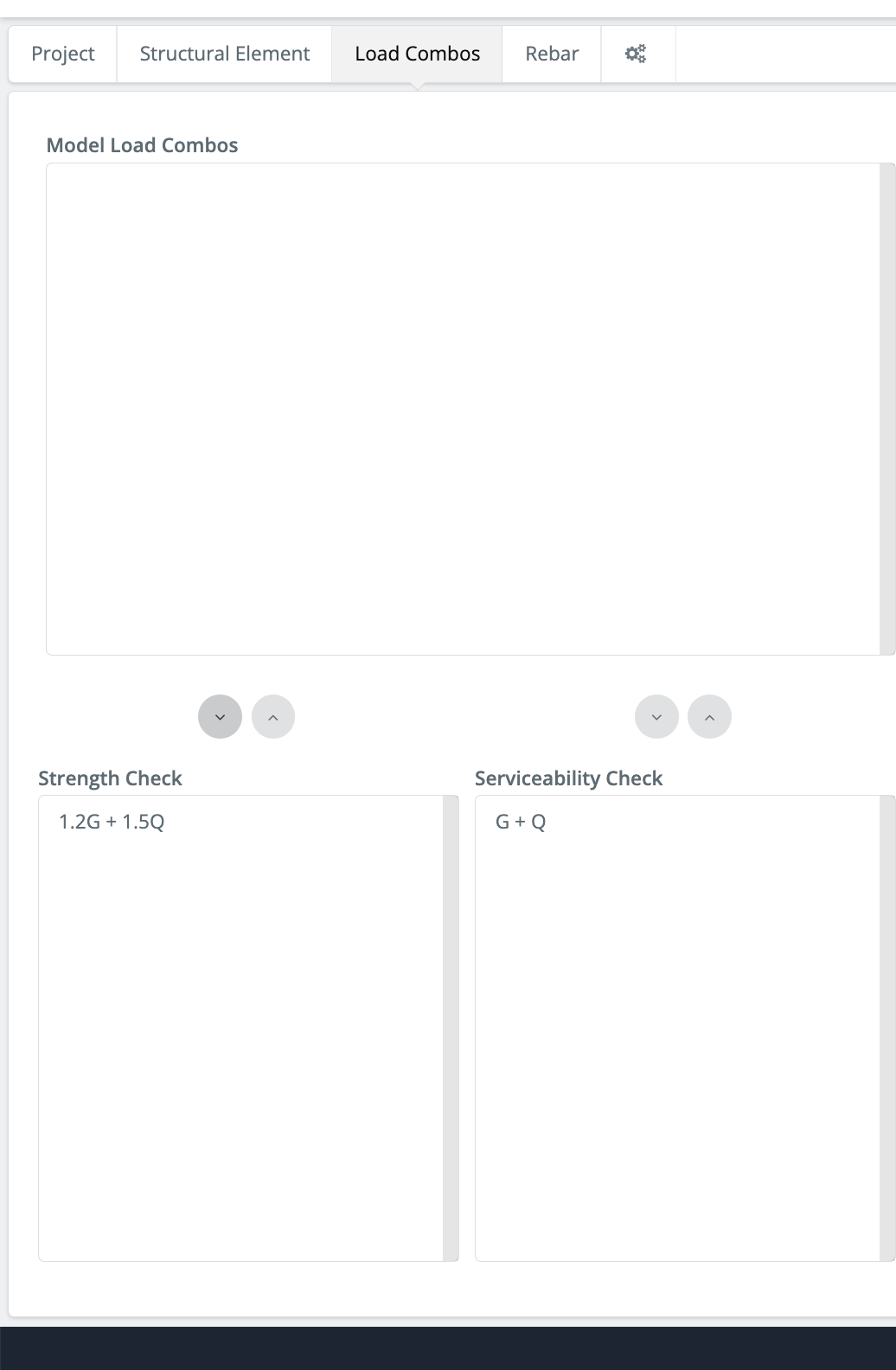
Next we can go to the Load Combos tab to define our load combination to be used in the analysis. The Model Load Combos box will automatically display load combinations that were defined in the S3D model. We then assign each relevant load case to a Strength Check or Serviceability Check by selecting the load combinations and clicking using the Down Arrow above the relevant box. If you need to reassign one of the load combinations, simply click the Up Arrow after selecting the combination to be reassigned.
We are now ready to check our reinforcement. Click Rebar tab to open the rebar menu. Selecting the structural element from the List of Elements, we can define reinforcement here using two methods:
Assign Reinforcement Manually – This method allows us to manually assign reinforcement to our slab. We can choose specific areas of the slab to assign reinforcement to allowing us to customise the reinforcement layout. We can specify the direction the reinforcement is to be assigned, the spacing and whether the reinforcement is placed on top or bottom of the slab. We can then go back to the main Rebar tab by clicking back and run checks on the reinforcement we have assigned by clicking Check. This will present a utility ratio for moment capacity, shear capacity and crack widths.
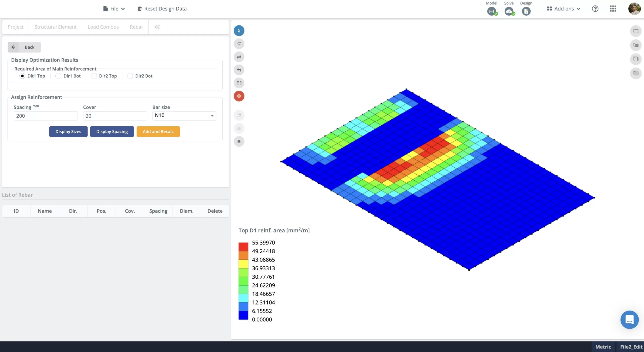
Assign Reinforcement Data Based On Optimisation Result – Here the reinforcement required to meet strength, shear and crack width requirements is optimised and presented as a mm2/m rate. Note the results presented refer to the amount of additional reinforcement required to satisfy strength and serviceability check. Any reinforcement assigned in the manual reinforcement tab will be factored into these checks and therefore if the manually assigned reinforcement already exceeds the strength and serviceability checks, the additional reinforcement required will show as 0 mm2/m for the relevant area.
FAQ
The RC Slab Module is available through our professional subscription. You can check out pricing for all our accounts here: https://skyciv.com/checkout/
The Plate Design Module currently supports the following design codes:
- ACI 318-19
- EN 1992-1-1:2004
- AS 3600:2018
To request support for additional design codes, you can add feature requests here: https://skyciv.upvoty.com/b/rc-design/
When working with plates, solve times are heavily dependent on the mesh size. If you are finding your particular model is taking a long time to solve, try increasing the size of the mesh to reduce the number of nodes to be assessed during the analysis.
IMPORTANT: Increasing the mesh size will reduce the accuracy of the analysis. Always review your results to check they are behaving as expected.
- Modelling with Plates documentation
- Plate Design Module documentation
- More about SkyCiv Structural Analysis Software – S3D

