Residential Home Design
This tutorial helps walk you through the basics of using SkyCiv S3D to model a basic residential home design. This video will take you from a beginner to being able to model your own designs independently
If you are looking to use SkyCiv to model residential homes, this is the best place to start!
Introduction
This tutorial will walk you through how to design a simple Residential Home using SkyCiv Structural 3D. We will cover how to design walls and columns, use linear and fixed supports, update materials using Section Builder, create walls using the “Plate” and “Mesh” tools, add loads, and eventually analyze the design, print a final report, and using the Member Design module to finish the design of columns and beams.
Modeling – Nodes & Members
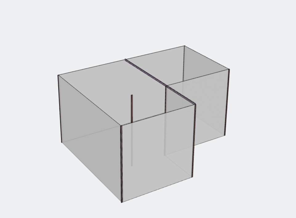
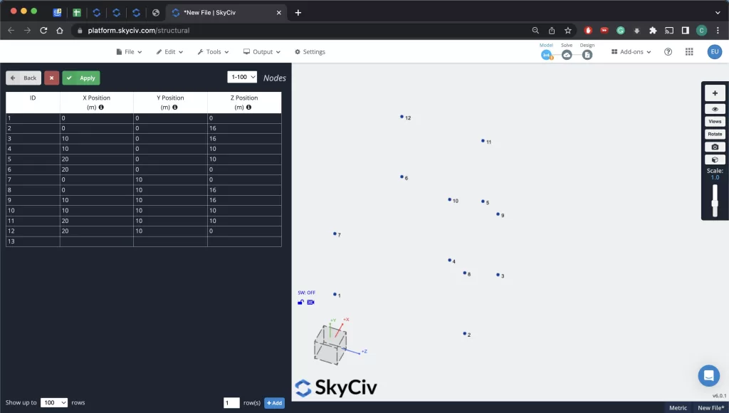
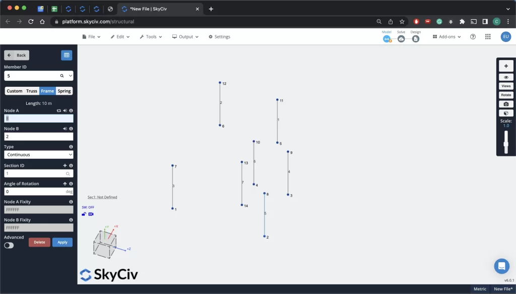
The first step in modeling a Residential Home is laying out the model for the project. First, you must lay out the nodes as well as the members to draw the geometry of the building. We will, later on, use this to define the walls of the structure as well as define the material of each member.
Walls & Columns
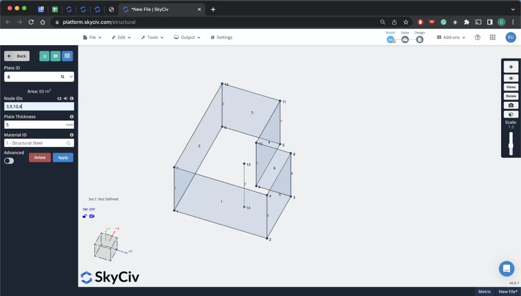
Now that the nodes have been defined it is time to define the walls and columns. By selecting the “Plate” tool from the dashboard, we can define the walls of the structure using four nodes for each wall corner. We can then select “5 – Concrete” as the material for the plate.
For columns, we can simply define a member from two points. We can update the material of the column once we begin defining sections in Section Builder.
Supports
Now that we have our walls, we can create wall supports by defining linear supports along the base of each wall. For this select the “Supports” section from the dashboard and select linear supports for each wall.
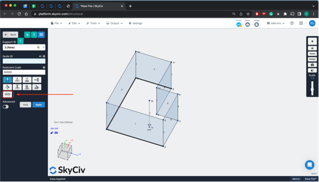
Loading
After you’ve modeled your walls, columns, and supports, it is time to define your loads. The documentation goes into detail on the various types of loads one can add in SkyCiv Structural 3D but the most loads for Residential Homes would be area loads along the walls as well as point and linear loads where the roof meets the walls. For this example, we will show how to define area loads and point loads.
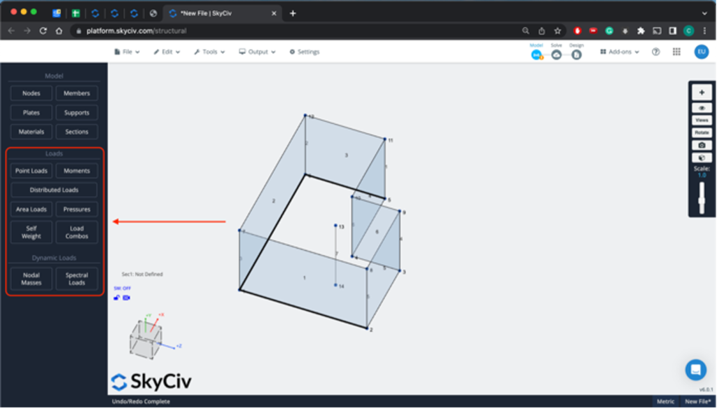
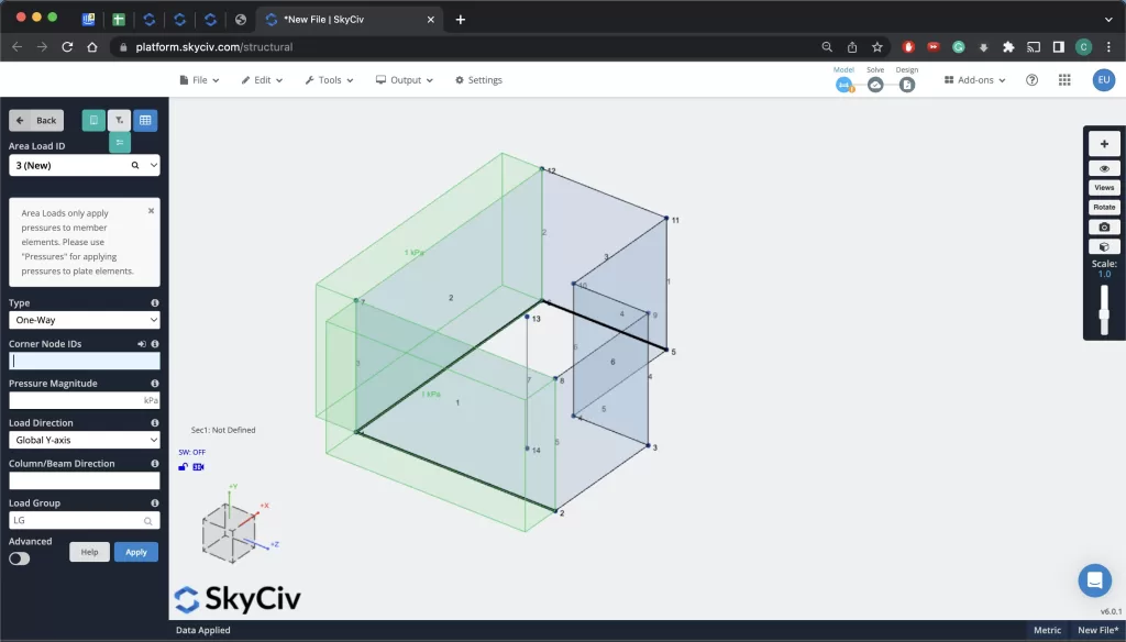
Select the applicable load type from the “Loads” section of the dashboard and then define the locations (using nodes and members) of the various loads for your design. Once you are done, it is time to move to the final step of modeling.
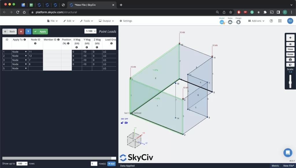
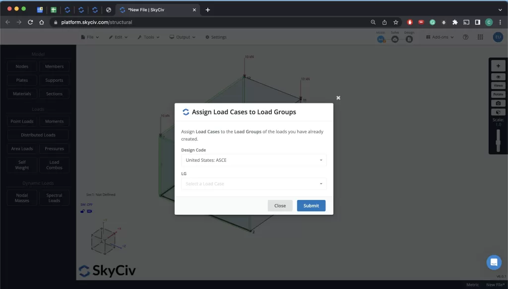
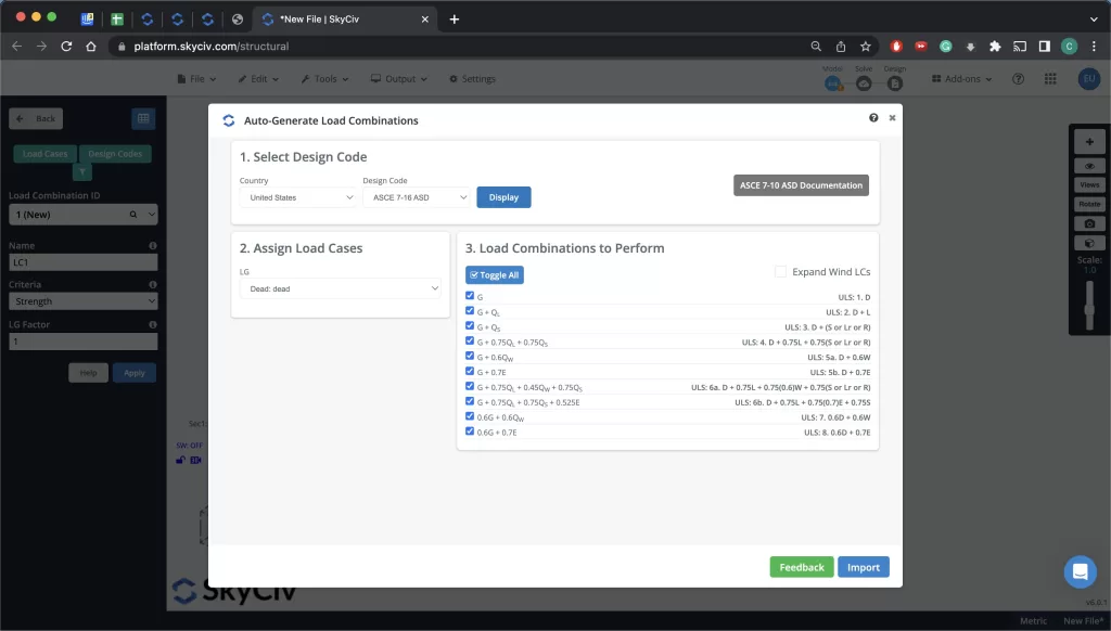
After the loads have been added, select “Load Combos” from the dashboard and define the Design Code you wish to use to analyze your model. After this has been selected, open “Load Combos” again and add the applicable Load Combinations for your final analysis.
Section Properties & Plate Materials
After you’ve modeled your building, you must define Section IDs for all members in your design as well as material values for all of the plates as well.
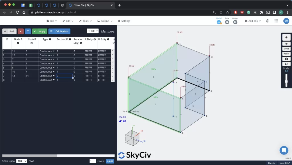
For defining the material of the columns and beams, simple navigate to the “Member” menu again and input a value for each type of section you would like to define.
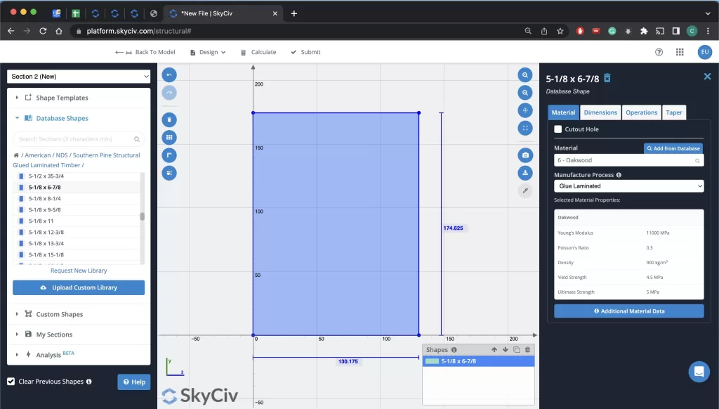
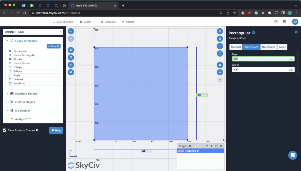
Next, from the “Sections” menu, select and open “Section Builder”. In this example, for the columns as well as the cross beam, two sections will be created (one for wood and one for concrete). You can select template shapes from the menu on the right and then use the menu on the right to fine-tune the values of your specific section. Once you are done, you can return to the model.
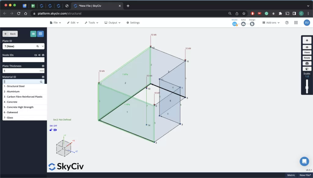
For defining the material of the walls, navigate to the “Plate” menu and select your desired “Material ID” for the material you wish to define. Lastly, ensure you run the Auto-Mesh tool to mesh all the plates that are defining the walls of your model.
Analyzing & Designing
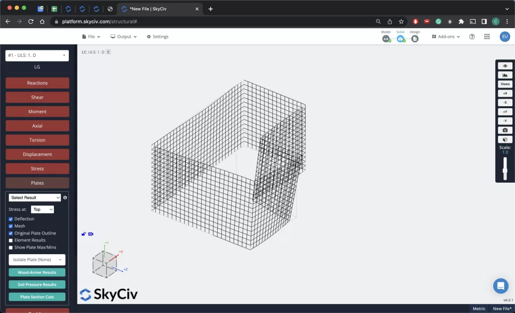
Now that you are done with modeling, adding loads, and defining you sections it is time to analyze your model. Select “Solve” in the top right menu bar and then begin the operation. Your model will be solved you can then analyze all your results.
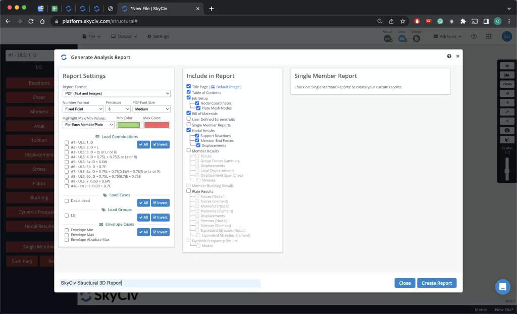
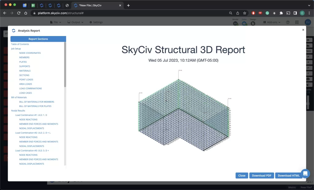
To generate a report of your project, select “Report” from the dashboard menu. After you’ve selected what you want to be included in the report you can select “Generate Report” and one will be produced in the background.
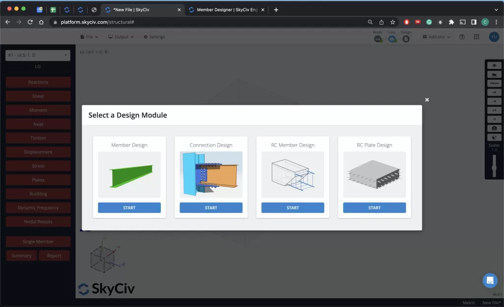
The last step is analyzing the members of your model. From the top right menu bar select “Design”, choose you applicable code. A menu will appear allowing you to select the “Member Design” module. Select this to move to the next step.
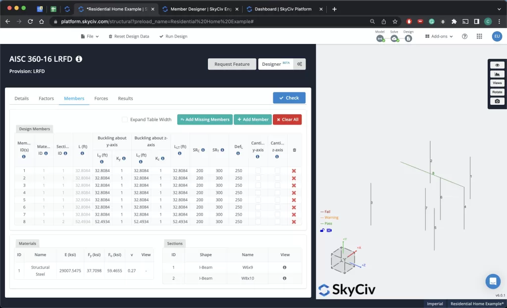
Once you are in the Member Design module, you can choose your design code to analyze with, analyze the various stresses, Moments, and other structural properties of your design, as well as use the Optimizer (Beta) to help you select the optimal beam/column size depending on your design parameters.
Now you have finalized your design and you know how to model a Residential Home in SkyCiv 3D, analyze your design, print a final report, and optimize the design of members!
FAQ
Yes! When you use Member Designer, it will only allow you to model and analyze one code/material type at a time (e.g. NDS/wood, AISC/steel, etc.) but you can always save your results, return to the solved model and analyze with another code/material afterwards.
You can view our pricing for a monthly subscription here.
Yes, Member Designer is a separate module from S3D but it is fully integrated and comes included with the purchase of a professional or enterprise license plan.


