How to Design an AISC Steel Connection in SkyCiv
Learn how to design a steel connection using SkyCiv Structural Analysis Software and the integrated Steel Connection Design module.
In this walkthrough we’ll look at modelling a simple frame (with some shortcuts!), reviewing the analysis results and performing some connection design using AISC!
Modelling a Steel Frame
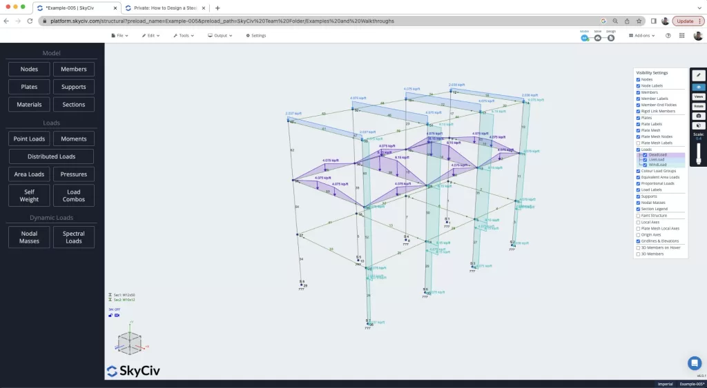
We start this walkthrough by first building a steel frame. If you’re already familiar with this part of the process, feel free to skip through! But we walkthrough how you can build a model like this in a few minutes, using some of the SkyCiv favorite features, including:
- Pen Tool – model quickly using the pen tool
- Copy and Paste – copy and paste substructures to easily build up your model
- Multi-edit – hold CTRL and drag the mouse to select and multi-edit parts of your model
- Search Sections – quick add sections from our library in seconds, using search
- Area Loads – one way, two way and wind load area loads that automatically calculate (and readjust!) the tributary areas of members.
- Design Code Load Combination – import ASCE 7-16 Load Combinations automatically
Reviewing Critical Member Forces
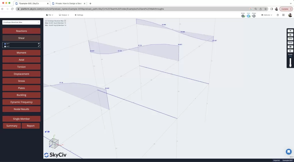
Now that we have solved the model, we take a look at the analysis results to try and find the worst case member forces for the basis of our connection design. Reviewing the Envelope Absolute Max results will show us the worst case forces in all our load combinations. We can also use the CTRL + drag functionality to isolate parts of our model. This is really helpful as we can review our model quickly, finding the worst case Shear Force at a member end as seen in this diagram, which we see member 14 having the worst shear force in the frame:
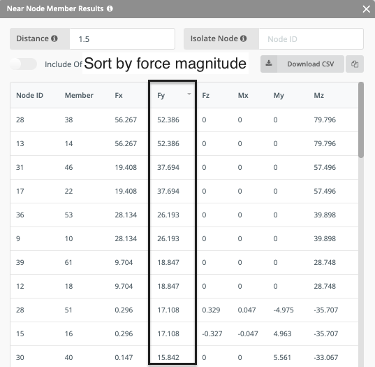
Another helpful feature we can use to identify this, is the Nodal Results. This is particularly useful in larger models where you may not be able to visually inspect and identify the worst case result. Here you can sort the table to make it easy to identify the highest force at a node, as well as it’s connected member. The table sort function is really useful here and can be used to sort the forces based on any force direction, in this case Fy:
Designing a Shear Connection
So we’ve identified the worse case connection in our model, now let’s design the connections based on this magnitude. The idea here is that we design them all as one type, which makes installation and construction easier. So, with this in mind we right click select beam 14 and the column 35 and open up the module. A lot of the information is pulled in from the analysis model, including:
- Beam Section properties
- Column Section properties
- Material properties
- Design Forces
Then we start the process of designing the connection assembly. This starts with selecting a connection type (shear, moment, axial etc..) as well as the design code, in this case AISC. The software will also warn the user if forces are detected in other directions with a yellow warning:
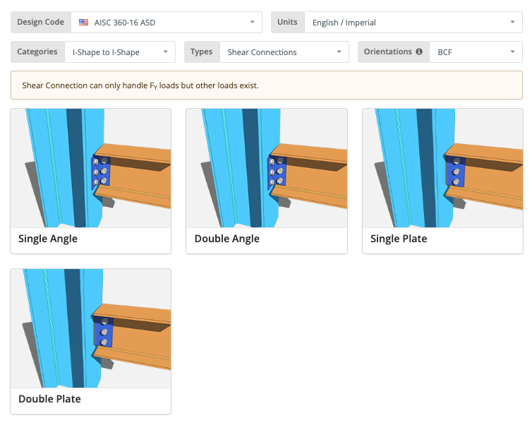
From there, we would select a connection, in this example we’re going with a double angle connection. Finally, we wish to design the fixtures to both the beam and column:
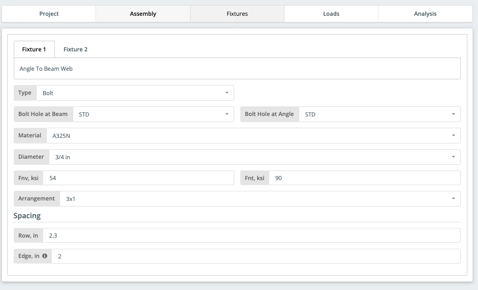
With easily identified input, it takes a couple of minutes to get your design ready. The Graphical interface helps users identify issues in their designs and at the same time provides instant feedback on your design and inputs. After completing the required input, you should have a design-ready connection:
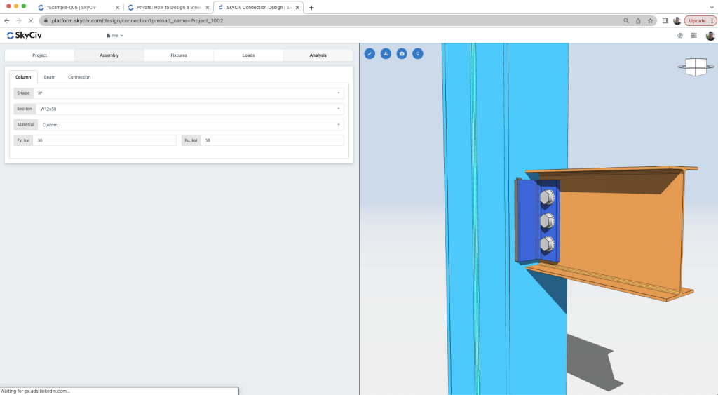
Reviewing the Calculations
The design check can now be run. The results are clear, informative and concise – with clear utility ratios being displayed, colour coded for pass/fail criteria:
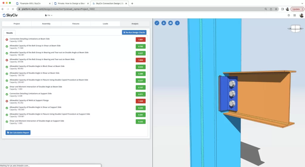
Clearly a number of checks are being performed, ranging from detailing checks, bolt checks, angle checks, welded checks, shear and flexure checks to name just a few. The software comes with powerful and clear reporting, helping the engineer to identify issues in their designs and understand how best to improve the design:
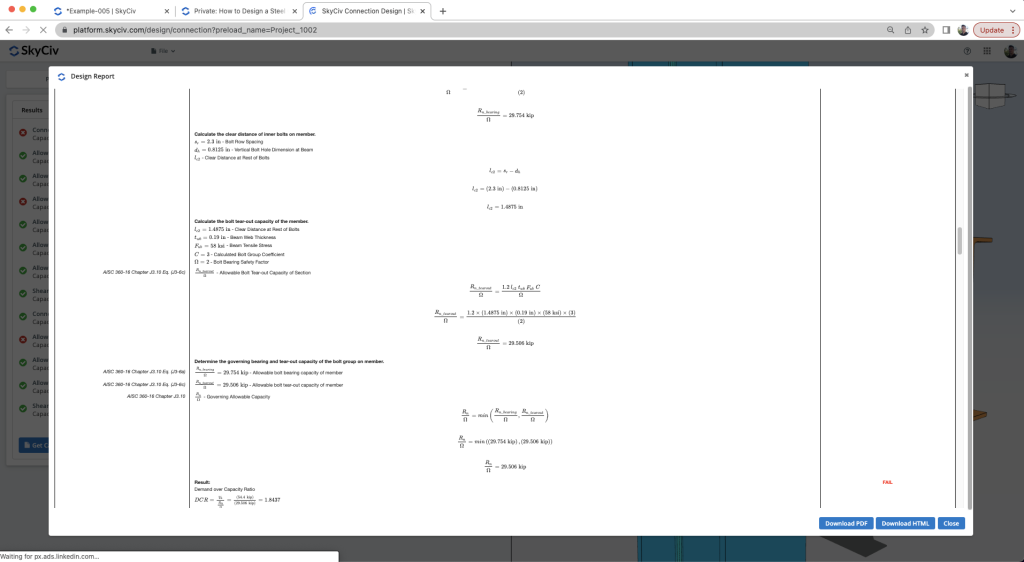
With this assistance, the user is given all the information they need to optimize or finalize a design. In this walkthrough, we demonstrate how the user can review the results, make changes to their design and get a better result.
FAQ
You can use a lateral bracing system to resist lateral loads making the beam left with shear loads only. If not, using rigid frames will require you to design connections with moment loads which is more costly.
You can model your structure as suggested above or you can change the fixity of your beam. You can also try changing the beam size to a stiffer one so moment loads can be carried by the beam as an internal load.
Make sure to check the members are supported. We currently only support American and Australian sizes and only I-shape or HSS/RHS/SHS shapes. Also make sure it is a beam to beam/column connection and perfectly perpendicular to one another.
Check the calculation report. Every check should intuitively tells you what to change. If a bolt check fails, you can change the bolt diameter or the bolt grade or you can change the bolt spacing. If the weld fails, you can increase weld size or increase the connection length to increase the weld length. If connector (plate, angle, etc.) fails, increase its thickness or length. If the beam or column fails, you can change the size in S3D or try making the connection bigger.

